Switch Starting Position Switch Starting Position |
|---|
Switch Action Switch Action |
|---|
|
Wire Connection Type Wire Connection Type |
|---|
 | |
| Screw Terminals | Wire Leads |
Industry Designation Industry Designation |
|---|
DFARS (Defense Acquisition Regulations Supplement) DFARS (Defense AcquisitionRegulations Supplement) |
|---|
Switch Type Switch Type |
|---|
|
Specifications Met Specifications Met |
|---|
|
RoHS (Restriction of Hazardous Substances) RoHS (Restriction ofHazardous Substances) |
|---|
|
REACH (Registration, Evaluation, Authorization and Restriction of Chemicals) REACH (Registration,Evaluation, Authorization and Restriction of Chemicals) |
|---|
|
Choosing an Electrical Switch
More
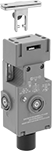
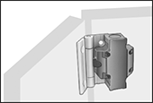
Frame-Mounted Safety Switches
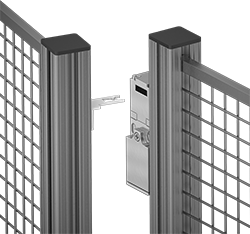
Also known as interlock switches, these ensure the safety of personnel by automatically shutting off power to machinery when an access door opens. Mount the switch to the door frame and mount a key to the door so that the key is inserted into the switch when the door is closed. When the door opens, the key is removed from the switch and the machine shuts down. They’re often used with machine guards.
Style A-F have positive-force, normally closed contacts that will open a circuit when the switch is actuated even if a spring fails or the contacts stick.
NEMA 6 rated switches protect against temporary submersion and washdowns.
NEMA 4 rated switches protect against washdowns.
IP67 rated switches protect against temporary submersion.
Flexible keys (sold separately) pivot 15° to make it easier to align with the switch during installation.
![]() For technical drawings and 3-D models, click on a part number.
For technical drawings and 3-D models, click on a part number.
Housing | ||||||||||||||||
|---|---|---|---|---|---|---|---|---|---|---|---|---|---|---|---|---|
| Style | No. of Circuits Controlled | Switch Starting Position | Switch Action | No. of Terminals | Industry Designation | Switching Current @ Voltage | Max. Voltage | Ht. | Wd. | Dp. | Conduit Trade Size | Conduit Thread Size | Key Included | Environmental Rating | Each | |
Wire Lead Connection with Positive-Force Normally Closed Contacts | ||||||||||||||||
| A | 2 | 1 Off (Normally Open) and 1 On (Normally Closed) | Stays Switched (Maintained) | 2 | DPST-1NO/1NC | 8 A @ 120 V AC, 4 A @ 24 V DC | 24V DC 250V AC | 3.3" | 1.2" | 1.2" | __ | M16 | Yes | IP67 | 00000000 | 0000000 |
Screw Terminal Connection with Positive-Force Normally Closed Contacts | ||||||||||||||||
| B | 2 | 1 Off (Normally Open) and 1 On (Normally Closed) | Stays Switched (Maintained) | 4 | DPST-1NO/1NC | 5 A @ 120 V AC, 2 A @ 24 V DC | 250V DC 500V AC | 3" | 1" | 1.1" | 1/2 | __ | Yes | NEMA 6, IP67 | 00000000 | 000000 |
| C | 2 | 1 Off (Normally Open) and 1 On (Normally Closed) | Stays Switched (Maintained) | 4 | DPST-1NO/1NC | 10 A @ 120 V AC, 2 A @ 24 V DC | 24V DC 250V AC | 3.6" | 2.1" | 1.3" | 1/2 | __ | Yes | NEMA 4, IP65 | 00000000 | 000000 |
| C | 3 | 1 Off (Normally Open) and 2 On (Normally Closed) | Stays Switched (Maintained) | 3 | 3PST-1NO/2NC | 8 A @ 120 V AC, 4 A @ 24 V DC | 250V DC 600V AC | 3.5" | 2.1" | 1.2" | 1/2 | __ | Yes | IP67 | 00000000 | 000000 |
| C | 3 | 1 Off (Normally Open) and 2 On (Normally Closed) | Stays Switched (Maintained) | 6 | 3PST-1NO/2NC | 4 A @ 230 V AC, 4 A @ 24 V DC | 24V DC 500V AC | 3.5" | 2" | 1.2" | __ | M16 | Yes | IP67 | 00000000 | 000000 |
| D | 3 | 1 Off (Normally Open) and 2 On (Normally Closed) | Stays Switched (Maintained) | 6 | 3PST-1NO/2NC | 6 A @ 120 V AC, 0.27 A @ 24 V DC | 240V AC 250V DC | 3.8" | 1.2" | 1.2" | 1/2 | __ | Yes | IP67 | 00000000 | 00000 |
| E | 2 | 1 Off (Normally Open) and 1 On (Normally Closed) | Stays Switched (Maintained) | 4 | DPST-1NO/1NC | 8 A @ 230 V AC, 5 A @ 24 V DC | 24V DC 400V AC | 4.2" | 2" | 1.6" | __ | M20 | No | IP67 | 00000000 | 00000 |
| E | 2 | 2 On (Normally Closed) | Stays Switched (Maintained) | 4 | DPST-NC | 8 A @ 230 V AC, 5 A @ 24 V DC | 24V DC 400V AC | 4.2" | 2" | 1.6" | __ | M20 | No | IP67 | 00000000 | 00000 |
Screw Terminal Connection with Positive-Force Normally Closed Contacts and Rotating Head | ||||||||||||||||
| C | 3 | 1 Off (Normally Open) and 2 On (Normally Closed) | Stays Switched (Maintained) | 6 | 3PST-1NO/2NC | 6 A @ 120 V AC, 2.5 A @ 24 V DC | 250V DC 500V AC | 3.9" | 2.3" | 1.3" | 1/2 | __ | Yes | NEMA 6, IP67 | 00000000 | 000000 |
| D | 3 | 1 Off (Normally Open) and 2 On (Normally Closed) | Stays Switched (Maintained) | 6 | 3PST-1NO/2NC | 10 A @ 120 V AC, 2.5 A @ 125 V DC | 120V AC 125V DC | 3.8" | 1.2" | 1.2" | __ | M20 | No | IP67 | 00000000 | 00000 |
| F | 3 | 1 Off (Normally Open) and 2 On (Normally Closed) | Stays Switched (Maintained) | 6 | 3PST-1NO/2NC | 10 A @ 230 V AC, 4 A @ 24 V DC | 24V DC 250V AC | 4.3" | 1.6" | 1.4" | __ | M20 | No | IP67 | 00000000 | 000000 |
Screw Terminal Connection with Rotating Head | ||||||||||||||||
| G | 4 | 2 Off (Normally Open) and 2 On (Normally Closed) | Stays Switched (Maintained) | 8 | 4PST-2NO/2NC | 2.5 A @ 120 V AC, 1 A @ 125 V DC | 120V AC 125V DC | 7.1" | 1.5" | 1.5" | 1/2 | __ | No | IP67 | 00000000 | 000000 |
O'all | |||||||
|---|---|---|---|---|---|---|---|
| Angle Range | Adjustability | Lg. | Wd. | Mounting Fasteners Included | Each | ||
Straight Keys | |||||||
| For Style G | __ | __ | 48.5mm | 35mm | No | 00000000 | 000000 |
| For 65665K19 | __ | __ | 86mm | 32mm | No | 00000000 | 00000 |
| For Style E | __ | __ | 80mm | 32mm | No | 00000000 | 0000 |
90° Angle Keys | |||||||
| For Style E | __ | __ | 65.5mm | 32mm | No | 00000000 | 00000 |
Flexible Keys | |||||||
| For Style D | 0°-15° | Up/Down/Left/Right | 48.9mm | 55mm | No | 000000000 | 00000 |
| For Style G | 0°-15° | Up/Down/Left/Right | 50.4mm | 55mm | No | 00000000 | 00000 |
| For 65665K19 | 0°-15° | Up/Down/Left/Right | 105mm | 40mm | No | 00000000 | 000000 |
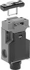
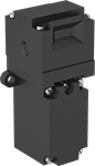
Access-Delay Frame-Mounted Safety Switches
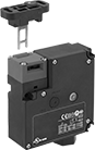
Delay access to hazardous areas until conditions are safe; use these switches with machines that take time to stop after they are turned off. Mount the switch to the door frame and mount the key to the door so that the key is inserted into the switch when the door is closed. When the door is pulled, the key is held in place with 225 lbs. of force until the switch receives a signal from a time-delay relay, motion sensor, or position sensor (not included) that the machine’s motion has stopped. After the motion has stopped, the key can be removed from the switch, releasing the access door. They’re often used with machine guards. All have positive-force, normally-closed contacts that will open a circuit when the switch is actuated even if a spring fails or the contacts stick. They’re rated for protection from washdowns and temporary submersion.
Style A and B have a key entry on the top and side of the switch.
Style C has a key entry on two opposite sides of the switch.
Emergency override keys (sold separately) bypass the access delay feature.
![]() For technical drawings and 3-D models, click on a part number.
For technical drawings and 3-D models, click on a part number.
Housing | ||||||||||||||||
|---|---|---|---|---|---|---|---|---|---|---|---|---|---|---|---|---|
| Style | No. of Circuits Controlled | Switch Starting Position | Switch Action | No. of Terminals | Industry Designation | Switching Current @ Voltage | Max. Voltage | Input Voltage | Holding Force, lbs. | Ht. | Wd. | Dp. | Wire Connection Type | Conduit Trade Size | Each | |
Positive-Force Normally Closed Contacts | ||||||||||||||||
| A | 3 | 1 Off (Normally Open) and 2 On (Normally Closed) | Stays Switched (Maintained) | 6 | 3PST-1NO/2NC | 5 A @ 120 V AC, 2 A @ 24 V DC | 500V AC 250V DC | 24V AC, 24V DC | 225 | 4.7" | 2.3" | 1.4" | Screw Terminals | 1/2 | 0000000 | 0000000 |
| A | 3 | 1 Off (Normally Open) and 2 On (Normally Closed) | Stays Switched (Maintained) | 6 | 3PST-1NO/2NC | 5 A @ 120 V AC, 2 A @ 24 V DC | 500V AC 250V DC | 110V AC | 225 | 4.7" | 2.3" | 1.4" | Screw Terminals | 1/2 | 0000000 | 000000 |
| B | 3 | 1 Off (Normally Open) and 2 On (Normally Closed) | Stays Switched (Maintained) | 14 | 3PST-1NO/2NC | 3 A @ 120 V AC, 2.5 A @ 24 V DC | 250V DC 240V AC | 24V DC | 225 | 3.7" | 3.5" | 1.4" | Screw Terminals | 1/2 | 0000000 | 000000 |
Positive-Force Normally Closed Contacts and Rotating Head | ||||||||||||||||
| C | 4 | 2 Off (Normally Open) and 2 On (Normally Closed) | Stays Switched (Maintained) | 8 | 4PST-2NO/2NC | 4 A @ 120 V AC, 4 A @ 24 V DC | 240V AC 24V DC | 24V AC, 24V DC | 225 | 7.6" | 1.2" | 1.6" | Screw Terminals | 1/2 | 0000000 | 000000 |
| Emergency Override Key for Style A | 0000000 | Each | 000000 |
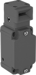
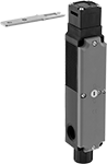
Hinge-Actuated Safety Switches
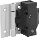
Replace access door hinges with these switches; they actuate when the door opens at least 4°. Also known as interlock switches, they ensure the safety of personnel by automatically shutting off power to machinery when an access door opens. All have positive-force, normally-closed contacts that will open a circuit when the switch is actuated even if a spring fails or the contacts stick. In addition to access doors, these switches can also be used on machine guards constructed from aluminum T-slotted framing. They’re rated IP65 for protection from washdowns.
![]() For technical drawings and 3-D models, click on a part number.
For technical drawings and 3-D models, click on a part number.
Overall | ||||||||||||
|---|---|---|---|---|---|---|---|---|---|---|---|---|
| No. of Circuits Controlled | Switch Starting Position | Switch Action | No. of Terminals | Industry Designation | Switching Current @ Voltage | Wire Connection Type | Conduit Thread Size | Ht. | Wd. | Dp. | Each | |
| 3 | 1 Off (Normally Open) and 2 On (Normally Closed) | Springs Back (Momentary) | 6 | 3PST-1NO/2NC | 2 A @ 250 V AC | Screw Terminals | M20 | 3.62" | 4.39" | 1.42" | 0000000 | 0000000 |
Enclosure Door Switches
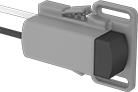
Activate or deactivate fans, lights, and other devices inside your enclosure when you open or close the door. These switches work with most enclosures, since you can slide the housing up to 1 3/8” to make the switch longer or shorter. Mount screws anywhere along the mounting slots to install.
Normally open switches activate a device such as a fan when you close the door.
Normally closed switches set off an alarm, light, or other device when you open the door.
Normally open and normally closed switches control two devices at the same time—for example, use them to turn a light on and a fan off when you open the door.
![]() For technical drawings and 3-D models, click on a part number.
For technical drawings and 3-D models, click on a part number.
Switching | For Wire | ||||||||||||
|---|---|---|---|---|---|---|---|---|---|---|---|---|---|
| Number of Circuits Controlled | Switch Action | Number of Terminals | Industry Designation | Current, A | Voltage | Maximum Voltage | Gauge | Number of | Overall Length | Environmental Rating | Specifications Met | Each | |
Plastic Actuator with Wire Leads | |||||||||||||
1 Off (Normally Open) | |||||||||||||
| 1 | Springs Back (Momentary) | 4 | SPST-NO | 8 | 250V AC | 250V AC | 16-14 | 2 | 4 1/4" | IP20 | CE Marked | 0000000 | 000000 |
1 On (Normally Closed) | |||||||||||||
| 1 | Springs Back (Momentary) | 2 | SPST-NC | 8 | 250V AC | 250V AC | 16-14 | 2 | 4 1/4" | IP20 | CE Marked | 0000000 | 00000 |
1 Off (Normally Open) and 1 On (Normally Closed) | |||||||||||||
| 2 | Springs Back (Momentary) | 4 | DPST-1NO/1NC | 8 | 250V AC | 250V AC | 16-14 | 2 | 4 1/4" | IP20 | CE Marked | 0000000 | 00000 |
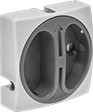
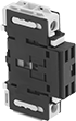
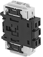
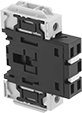
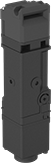
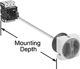
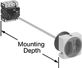
Enclosure Disconnect Switches
Install these switches inside an enclosure to prevent it from opening when power is on—turn the switch to disconnect power and release the door. Cut the shaft to fit the enclosure. Use a padlock (not included) to lock switches in the off position. Mount to DIN rail inside an enclosure; mounting depth is the distance from the panel door to the DIN rail. UL listed, C-UL listed, and CE marked, these switches meet American, Canadian, and European safety standards.
Use optional sealing gaskets in washdown environments; they create an IP65 rated seal around the actuator.
Add auxiliary contact blocks to send a signal or connect to another device, such as an alarm or indicating light.
Use additional power poles to control more than three circuits. Add neutral poles to open and close the neutral leg of a three phase system.
Add junction blocks to connect a ground wire.
Terminal covers prevent contact with live terminals.
Switching | |||||||||
|---|---|---|---|---|---|---|---|---|---|
| Current, A | Voltage | Electrical Phase (hp) | Ht. | Wd. | For DIN Rail Ht., mm | Mounting Dp. | Environmental Rating | Each | |
Yellow Plastic Housing with Red Actuator | |||||||||
3 Circuits with Lockout—For 1 3/16" Panel Cutout Dia. | |||||||||
| 25 | 600V AC | Single (3/4 hp @ 120 V AC) Single (1 1/2 hp @ 240 V AC) Three (1 1/2 hp @ 120 V AC) Three (3 hp @ 240 V AC) | 2 5/8" | 2 5/8" | 35 | 4 7/8"-15 3/4" | IP40 | 0000000 | 000000 |
| 32 | 600V AC | Single (1 hp @ 120 V AC) Single (2 hp @ 240 V AC) Three (2 hp @ 120 V AC) Three (5 hp @ 240 V AC) | 2 5/8" | 2 5/8" | 35 | 4 7/8"-15 3/4" | IP40 | 0000000 | 00000 |
| 50 | 600V AC | Single (1 1/2 hp @ 120 V AC) Single (3 hp @ 240 V AC) Three (3 hp @ 120 V AC) Three (7 1/2 hp @ 240 V AC) | 2 5/8" | 2 5/8" | 35 | 5 5/16"-16 1/8" | IP40 | 0000000 | 00000 |
| 63 | 600V AC | Single (3 hp @ 120 V AC) Single (5 hp @ 240 V AC) Three (5 hp @ 120 V AC) Three (10 hp @ 240 V AC) | 2 5/8" | 2 5/8" | 35 | 5 5/16"-16 1/8" | IP40 | 0000000 | 000000 |
| 80 | 600V AC | Single (3 hp @ 120 V AC) Single (10 hp @ 240 V AC) Three (7 1/2 hp @ 120 V AC) Three (20 hp @ 240 V AC) | 3 3/8" | 3 3/8" | 35 | 5 11/16"-16 1/2" | IP40 | 0000000 | 000000 |
| 100 | 600V AC | Single (5 hp @ 120 V AC) Single (10 hp @ 240 V AC) Three (10 hp @ 120 V AC) Three (25 hp @ 240 V AC) | 3 3/8" | 3 3/8" | 35 | 5 11/16"-16 1/2" | IP40 | 0000000 | 000000 |
4 Circuits with Lockout—For 1 3/16" Panel Cutout Dia. | |||||||||
| 25 | 600V AC | Single (3/4 hp @ 120 V AC) Single (1 1/2 hp @ 240 V AC) Three (1 1/2 hp @ 120 V AC) Three (3 hp @ 240 V AC) | 2 5/8" | 2 5/8" | 35 | 4 7/8"-15 3/4" | IP40 | 0000000 | 00000 |
| 32 | 600V AC | Single (1 hp @ 120 V AC) Single (2 hp @ 240 V AC) Three (2 hp @ 120 V AC) Three (5 hp @ 240 V AC) | 2 5/8" | 2 5/8" | 35 | 4 7/8"-15 3/4" | IP40 | 0000000 | 000000 |
| 50 | 600V AC | Single (1 1/2 hp @ 120 V AC) Single (3 hp @ 240 V AC) Three (3 hp @ 120 V AC) Three (7 1/2 hp @ 240 V AC) | 2 5/8" | 2 5/8" | 35 | 5 5/16"-16 1/8" | IP40 | 0000000 | 000000 |
| 63 | 600V AC | Single (3 hp @ 120 V AC) Single (5 hp @ 240 V AC) Three (5 hp @ 120 V AC) Three (10 hp @ 240 V AC) | 2 5/8" | 2 5/8" | 35 | 5 5/16"-16 1/8" | IP40 | 0000000 | 000000 |
| 80 | 600V AC | Single (3 hp @ 120 V AC) Single (10 hp @ 240 V AC) Three (7 1/2 hp @ 120 V AC) Three (20 hp @ 240 V AC) | 3 3/8" | 3 3/8" | 35 | 5 11/16"-16 1/2" | IP40 | 0000000 | 000000 |
| 100 | 600V AC | Single (5 hp @ 120 V AC) Single (10 hp @ 240 V AC) Three (10 hp @ 120 V AC) Three (25 hp @ 240 V AC) | 3 3/8" | 3 3/8" | 35 | 5 11/16"-16 1/2" | IP40 | 0000000 | 000000 |
Gray Plastic Housing with Gray Actuator | |||||||||
3 Circuits with Lockout—For 1 3/16" Panel Cutout Dia. | |||||||||
| 25 | 600V AC | Single (3/4 hp @ 120 V AC) Single (1 1/2 hp @ 240 V AC) Three (1 1/2 hp @ 120 V AC) Three (3 hp @ 240 V AC) | 2 5/8" | 2 5/8" | 35 | 4 7/8"-15 3/4" | IP40 | 0000000 | 00000 |
| 32 | 600V AC | Single (1 hp @ 120 V AC) Single (2 hp @ 240 V AC) Three (2 hp @ 120 V AC) Three (5 hp @ 240 V AC) | 2 5/8" | 2 5/8" | 35 | 4 7/8"-15 3/4" | IP40 | 0000000 | 00000 |
| 50 | 600V AC | Single (1 1/2 hp @ 120 V AC) Single (3 hp @ 240 V AC) Three (3 hp @ 120 V AC) Three (7 1/2 hp @ 240 V AC) | 2 5/8" | 2 5/8" | 35 | 5 5/16"-16 1/8" | IP40 | 0000000 | 00000 |
| 63 | 600V AC | Single (3 hp @ 120 V AC) Single (5 hp @ 240 V AC) Three (5 hp @ 120 V AC) Three (10 hp @ 240 V AC) | 2 5/8" | 2 5/8" | 35 | 5 5/16"-16 1/8" | IP40 | 0000000 | 000000 |
| 80 | 600V AC | Single (3 hp @ 120 V AC) Single (10 hp @ 240 V AC) Three (7 1/2 hp @ 120 V AC) Three (20 hp @ 240 V AC) | 3 3/8" | 3 3/8" | 35 | 5 11/16"-16 1/2" | IP40 | 0000000 | 000000 |
| 100 | 600V AC | Single (5 hp @ 120 V AC) Single (10 hp @ 240 V AC) Three (10 hp @ 120 V AC) Three (25 hp @ 240 V AC) | 3 3/8" | 3 3/8" | 35 | 5 11/16"-16 1/2" | IP40 | 0000000 | 000000 |