


Valve Function Valve Function |
|---|
|
Actuation Actuation |
|---|
--30402310031599830276-p9@1x_637354092326867916.png?ver=imagenotfound) | |
| Pressure | Electric (Solenoid) |
| Manual | Air |
Overall Length Overall Length |
|---|
Maximum Flow Rate Maximum Flow Rate |
|---|
Flow Coefficient (Cv) Flow Coefficient (Cv) |
|---|
Maximum Temperature Maximum Temperature |
|---|
|
|
|
RoHS (Restriction of Hazardous Substances) RoHS (Restriction ofHazardous Substances) |
|---|
|
REACH (Registration, Evaluation, Authorization and Restriction of Chemicals) REACH (Registration,Evaluation, Authorization and Restriction of Chemicals) |
|---|
|
Matching Flow Diagrams to Replace an Air Directional Control Valve
More
Choosing an Air Directional Control Valve
More
About Flow Control Valves
Also known as cylinder speed controls, flow control valves let you control the extension or retraction speed of your air cylinder. They regulate airflow as it passes from the valve's inlet to its outlet. Air flows freely in the opposite direction.
More
About Air Preparation
More
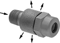
Elbow Air-Exhaust Control Valves
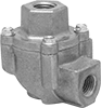
Inlet × Threaded
Female Outlet
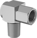
The 90° elbow shape allows you to install these valves in tight spaces. They quickly vent exhaust air to the atmosphere or divert it to another place in your system to speed up the movement of air cylinders. Also known as quick exhaust valves.
NPTF (Dryseal) threads are compatible with NPT threads.
Flow coefficient (Cv) is a measurement that indicates how much airflow can pass through a valve. When selecting between valves with the same port size, choose the valve with the higher flow coefficient to ensure it provides enough airflow to operate your system.
![]() For technical drawings and 3-D models, click on a part number.
For technical drawings and 3-D models, click on a part number.
Valves | |||||||||||||||
|---|---|---|---|---|---|---|---|---|---|---|---|---|---|---|---|
Overall | Repair Kits | ||||||||||||||
| No. of Flow Ports | Inlet Size | Outlet Size | Exhaust Connection Type | Max. Flow Rate, scfm @ 100 psi | Flow Coefficient (Cv) | Pressure Range, psi | Body Material | Lg. | Wd. | Ht. | Each | Includes | Each | ||
Threaded Female Inlet × Threaded Female Outlet | |||||||||||||||
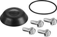
| 3 | 1/8 NPT | 1/4 NPT | Threaded | 61 | 1 | 20-125 | Aluminum | 1 7/8" | 1 5/8" | 1 7/16" | 0000000 | 000000 | Diaphragm, O-ring, Screws | 00000000 | 00000 |
| 3 | 1/8 NPT | 1/8 NPT | Threaded | 58 | 1.09 | 15-150 | Brass | 1 1/8" | 3/4" | 1" | 0000000 | 00000 | __ | 000000 | 00 |
| 3 | 1/4 NPT | 1/4 NPT | Threaded | 141 | 2.33 | 20-125 | Aluminum | 2 1/16" | 1 9/16" | 2 1/8" | 0000000 | 00000 | Diaphragm, O-ring, Screws | 00000000 | 0000 |
| 3 | 1/4 NPT | 1/4 NPT | Threaded | 65 | 1 | 20-125 | Aluminum | 1 7/8" | 1 5/8" | 1 7/16" | 0000000 | 00000 | Diaphragm, O-ring, Screws | 00000000 | 0000 |
| 3 | 1/4 NPTF | 1/4 NPTF | Threaded | 159 | 2.71 | 30-125 | Aluminum | 1 3/4" | 1 7/8" | 2 9/16" | 0000000 | 00000 | Diaphragm | 00000000 | 00000 |
| 3 | 3/8 NPT | 3/8 NPT | Threaded | 178 | 2.98 | 20-125 | Aluminum | 2 1/16" | 1 9/16" | 2 1/8" | 0000000 | 00000 | Diaphragm, O-ring, Screws | 00000000 | 0000 |
| 3 | 3/8 NPTF | 3/8 NPTF | Threaded | __ | 3.13 | 30-125 | Zinc | 1 3/4" | 1 7/8" | 2 9/16" | 0000000 | 000000 | Diaphragm | 00000000 | 00000 |
| 3 | 1/2 NPT | 1/2 NPT | Threaded | 336 | 5.45 | 20-125 | Aluminum | 3 1/8" | 2 15/16" | 3 5/16" | 0000000 | 00000 | Diaphragm, O-ring, Screws | 00000000 | 0000 |
| 3 | 3/4 NPT | 3/4 NPT | Threaded | 447 | 7.84 | 20-125 | Aluminum | 3 1/8" | 2 15/16" | 3 5/16" | 0000000 | 00000 | Diaphragm, O-ring, Screws | 00000000 | 0000 |
Threaded Female Inlet × Threaded Male Outlet | |||||||||||||||
| 3 | 1/8 NPT | 1/4 NPT | Threaded | 58 | 1.09 | 15-150 | Brass | 1 5/16" | 3/4" | 1 1/2" | 0000000 | 00000 | __ | 000000 | 00 |
| 3 | 1/8 NPT | 1/8 NPT | Threaded | 58 | 1.09 | 15-150 | Brass | 1 1/8" | 3/4" | 1 5/16" | 0000000 | 00000 | __ | 000000 | 00 |
| 3 | 1/4 NPT | 1/4 NPT | Threaded | 58 | 1.09 | 15-150 | Brass | 1 1/8" | 3/4" | 1 1/2" | 0000000 | 00000 | __ | 000000 | 00 |
| 3 | 10-32 UNF | 10-32 UNF | Threaded | 9 | 0.17 | 15-150 | Brass | 5/8" | 1/4" | 1/2" | 0000000 | 00000 | __ | 000000 | 00 |
Elbow Air-Exhaust Control Valves with Flow Control
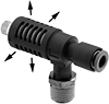
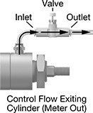
Control the flow of exhaust air while also regulating the exhaust air speed. These valves dump exhaust air to the atmosphere without routing it back through a directional control valve. They control flow in one direction as air flows from the inlet to the outlet, and adjust the volume of exhaust air exiting an air cylinder (meter out) to control its speed. Air flows freely in the opposite direction. They have a 90° elbow shape that allows you to install them in tight spaces. The push-to-connect outlet ports are for use with plastic or soft metal tubing; insert tubing into the ports. A muffler reduces exhaust noise. Also known as quick exhaust valves.
Flow coefficient (Cv) is a measurement that indicates how much airflow can pass through a valve. When selecting between valves with the same port size, choose the valve with the higher flow coefficient to ensure it provides enough airflow to operate your system.
![]() For technical drawings and 3-D models, click on a part number.
For technical drawings and 3-D models, click on a part number.
Overall | |||||||||||
|---|---|---|---|---|---|---|---|---|---|---|---|
| No. of Flow Ports | Inlet Size | For Outlet Tube OD | Max. Flow Rate, scfm @ 100 psi | Flow Coefficient (Cv) | Pressure Range, psi | Body Material | Lg. | Wd. | Ht. | Each | |
Threaded Male Inlet × Push-to-Connect Female Outlet | |||||||||||
| 3 | 1/8 NPT | 1/4" | 14.05 | 0.44 | 14-145 | PBT Plastic | 2 7/8" | 11/16" | 1 1/16" | 00000000 | 000000 |
| 3 | 1/8 NPT | 5/16" | 24.91 | 0.78 | 14-145 | PBT Plastic | 2 7/8" | 15/16" | 1 3/16" | 00000000 | 00000 |
| 3 | 1/8 NPT | 3/8" | 24.91 | 0.78 | 14-145 | PBT Plastic | 3 3/8" | 15/16" | 1 5/16" | 00000000 | 00000 |
| 3 | 1/4 NPT | 1/4" | 14.05 | 0.44 | 14-145 | PBT Plastic | 2 7/8" | 11/16" | 1 1/8" | 00000000 | 00000 |
| 3 | 1/4 NPT | 5/16" | 24.91 | 0.78 | 14-145 | PBT Plastic | 3 1/4" | 15/16" | 1 3/8" | 00000000 | 00000 |
| 3 | 1/4 NPT | 3/8" | 24.91 | 0.78 | 14-145 | PBT Plastic | 3 3/8" | 15/16" | 1 5/8" | 00000000 | 00000 |
| 3 | 1/4 NPT | 3/8" | 47.89 | 1.5 | 14-145 | PBT Plastic | 3 9/16" | 15/16" | 1 5/8" | 00000000 | 00000 |
| 3 | 3/8 NPT | 5/16" | 24.91 | 0.78 | 14-145 | PBT Plastic | 3 1/4" | 15/16" | 1 1/8" | 00000000 | 00000 |
| 3 | 3/8 NPT | 3/8" | 24.91 | 0.78 | 14-145 | PBT Plastic | 3 3/8" | 15/16" | 1 5/16" | 00000000 | 00000 |
| 3 | 3/8 NPT | 3/8" | 51.09 | 1.6 | 14-145 | PBT Plastic | 3 9/16" | 1 3/16" | 1 3/4" | 00000000 | 00000 |
| 3 | 1/2 NPT | 3/8" | 51.09 | 1.6 | 14-145 | PBT Plastic | 3 9/16" | 1 3/16" | 1 5/8" | 00000000 | 00000 |
Quiet Air-Exhaust Control Valves
A muffler on these valves reduces exhaust noise. They allow airflow into your equipment and then quickly vent exhaust air to the atmosphere without routing it back through a directional control valve to speed up the movement of equipment. Also known as quick exhaust valves.
Flow coefficient (Cv) is a measurement that indicates how much airflow can pass through a valve. When selecting between valves with the same port size, choose the valve with the higher flow coefficient to ensure it provides enough airflow to operate your system.
Overall | |||||||||||
|---|---|---|---|---|---|---|---|---|---|---|---|
| No. of Flow Ports | For Inlet Tube OD | For Outlet Tube OD | Maximum Flow Rate | Flow Coefficient (Cv) | Pressure Range, psi | Body Material | Lg. | Wd. | Ht. | Each | |
Push-to-Connect Female Inlet × Push-to-Connect Female Outlet | |||||||||||
| 3 | 1/4" | 1/4" | 11.36 scfm @ 100 psi | 0.8 | 14-145 | PBT Plastic | 2" | 1/2" | 3/4" | 0000000 | 000000 |
| 3 | 1/4" | 1/4" | 6.82 scfm @ 100 psi | 0.54 | 14-145 | PBT Plastic | 1 5/8" | 1/2" | 5/8" | 0000000 | 00000 |
| 3 | 4mm | 4mm | 4.47 scfm @ 100 psi | 0.14 | 14-145 | PBT Plastic | 39.7mm | 10mm | 14.3mm | 0000000 | 00000 |
| 3 | 6mm | 6mm | 11.36 scfm @ 100 psi | 0.8 | 14-145 | PBT Plastic | 44.5mm | 11.6mm | 19mm | 0000000 | 00000 |
| 3 | 6mm | 6mm | 4.79 scfm @ 100 psi | 0.15 | 14-145 | PBT Plastic | 41.3mm | 11.6mm | 15.9mm | 0000000 | 00000 |
Air-Exhaust Control Valves
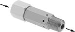
Allow airflow into your equipment and then quickly vent exhaust air to the atmosphere without routing it back through a directional control valve to speed up the movement of equipment. NPTF (Dryseal) threads are compatible with NPT threads. Also known as quick exhaust valves.
Flow coefficient (Cv) is a measurement that indicates how much airflow can pass through a valve.
![]() For technical drawings and 3-D models, click on a part number.
For technical drawings and 3-D models, click on a part number.
Overall | |||||||||||
|---|---|---|---|---|---|---|---|---|---|---|---|
| No. of Flow Ports | Inlet Size | Outlet Size | Max. Flow Rate, scfm @ 100 psi | Flow Coefficient (Cv) | Pressure Range, psi | Body Material | Lg. | Wd. | Ht. | Each | |
Threaded Female Inlet × Threaded Male Outlet | |||||||||||
| 3 | 1/8 NPTF | 1/8 NPTF | 6 | 0.1 | 30-125 | Aluminum and Brass | 1/2" | 1/2" | 1 13/16" | 0000000 | 000000 |
Air-Exhaust Flow Control Valves
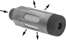
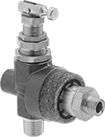
Install these valves in the exhaust ports of air directional control valves to control exhaust air speed without needing access to your cylinder. They control flow in one direction as air moves from the inlet to the exhaust port (meter out). Air flows freely in the opposite direction. Valves exhaust to the atmosphere and include a muffler to reduce the exhaust noise.
Flow coefficient (Cv) is a measurement that indicates how much airflow can pass through a valve. When selecting between valves with the same port size, choose the valve with the higher flow coefficient to ensure it provides enough airflow to operate your system.
![]() For technical drawings and 3-D models, click on a part number.
For technical drawings and 3-D models, click on a part number.
Overall | ||||||||||
|---|---|---|---|---|---|---|---|---|---|---|
| No. of Flow Ports | Inlet Size | Max. Flow Rate, scfm @ 100 psi | Flow Coefficient (Cv) | Max. Pressure, psi | Body Material | Hex Size | Dia. | Lg. | Each | |
Threaded Male Inlet | ||||||||||
Dial Flow Adjustment Mechanism | ||||||||||
| 2 | 1/8 BSPP | 35 | 1.016 | 145 | Aluminum | __ | 16mm | 46mm | 0000000 | 000000 |
| 2 | 1/4 BSPP | 52.5 | 1.524 | 145 | Aluminum | __ | 19.5mm | 63.3mm | 0000000 | 00000 |
| 2 | 3/8 BSPP | 59.5 | 1.728 | 145 | Aluminum | __ | 25mm | 95.3mm | 0000000 | 00000 |
| 2 | 1/2 BSPP | 141.26 | 2.982 | 145 | Aluminum | __ | 28mm | 130mm | 00000000 | 00000 |
| 2 | 3/4 BSPP | 268.39 | 5.965 | 145 | Aluminum | __ | 38mm | 157mm | 00000000 | 00000 |
Slotted Screw Flow Adjustment Mechanism | ||||||||||
| 2 | 1/8 NPT | 19.21 | 0.52 | 145 | Aluminum | 9/16" | 5/8" | 1 1/8" | 0000000 | 00000 |
| 2 | 1/8 BSPP | 19.21 | 0.52 | 145 | Aluminum | 14mm | 15mm | 27mm | 00000000 | 00000 |
| 2 | 1/4 NPT | 37 | 1 | 145 | Aluminum | 11/16" | 3/4" | 1 5/16" | 0000000 | 00000 |
| 2 | 1/4 BSPP | 37 | 1 | 145 | Aluminum | 17mm | 18.2mm | 32.1mm | 00000000 | 00000 |
| 2 | 3/8 NPT | 74 | 2 | 145 | Aluminum | 7/8" | 1" | 1 5/8" | 0000000 | 00000 |
| 2 | 3/8 BSPP | 74 | 2 | 145 | Aluminum | 22mm | 25mm | 41.1mm | 00000000 | 00000 |
| 2 | 1/2 NPT | 133.2 | 3.6 | 145 | Aluminum | 15/16" | 1 1/16" | 1 7/8" | 0000000 | 00000 |
| 2 | 1/2 BSPP | 133.2 | 3.6 | 145 | Aluminum | 24mm | 27mm | 44.6mm | 00000000 | 00000 |
Thumb Screw Flow Adjustment Mechanism | ||||||||||
| 2 | 1/8 BSPT | 10.59 | 0.201 | 145 | Brass | 10mm | 14mm | 35.8mm | 00000000 | 00000 |
| 2 | 1/4 BSPT | 17.66 | 0.313 | 145 | Brass | 14mm | 18mm | 37mm | 00000000 | 00000 |
| 2 | M5 Metric | 3.35 | 0.06 | 145 | Brass | 8mm | 10mm | 23.4mm | 00000000 | 00000 |
| 2 | M7 Metric | 4.24 | 0.075 | 145 | Brass | 8mm | 10mm | 26.9mm | 00000000 | 00000 |
Made-to-Order Air-Operated Air-Exhaust Control Valves
When these valves receive an air signal, they quickly dump exhaust air to the atmosphere without routing it back through a directional control valve to speed up the movement of equipment. They're often used with air compressors that require continuous operation. A muffler reduces exhaust noise. Also known as quick exhaust valves.
To Order: Specify minimum pressure and maximum pressure from the ranges listed. The difference between the minimum pressure and maximum pressure must be at least 10 psi, but no more than 30 psi.
Overall | |||||||||||||
|---|---|---|---|---|---|---|---|---|---|---|---|---|---|
| No. of Flow Ports | Inlet Size | For Outlet Tube ID | Air Pilot Size | Max. Flow Rate, scfm @ 100 psi | Flow Coefficient (Cv) | Body Material | Lg. | Wd. | Ht. | Choose a Pressure Range Min. | Choose a Pressure Range Max. | Each | |
Threaded Female Inlet × Barbed Male Outlet × Threaded Male Air Pilot | |||||||||||||
| 4 | 1/8 NPT | 1/4" | 1/4 NPT | 20 | Not Rated | Brass | 2 7/8" | 2 1/16" | 3 3/8" | 40 to 240 psi in 1 psi increments | 50 to 250 psi in 1 psi increments | 0000000 | 000000 |
Safety-Lockout Air On/Off Valves
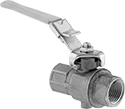
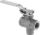
Padlocks that comply with OSHA 29 CFR 1910.147 meet standards for the control of energy sources that could injure workers.
![]() For technical drawings and 3-D models, click on a part number.
For technical drawings and 3-D models, click on a part number.
Flow Rate @ 100 psi | Overall | |||||||||||||
|---|---|---|---|---|---|---|---|---|---|---|---|---|---|---|
| Inlet Pipe Size | Outlet Pipe Size | Exhaust Pipe Size | Flow Coefficient (Cv) | Min. | Max. | Max. Pressure, psi | Temp. Range, °F | Lg. | Wd. | Ht. | For Max. Padlock Shackle Dia. | Specifications Met | Each | |
Brass Body | ||||||||||||||
| 1 1/4 | 1 1/4 | 1/4 | 86 | Not Rated | Not Rated | 200 | 32° to 210° | 8" | 2 5/16" | 4 3/4" | 9/32" | OSHA Compliant 29 CFR 1910.147 | 0000000 | 000000 |
| 1 1/2 | 1 1/2 | 1/4 | 140 | Not Rated | Not Rated | 200 | 32° to 210° | 8 3/16" | 2 13/16" | 5 1/4" | 9/32" | OSHA Compliant 29 CFR 1910.147 | 0000000 | 00000 |
| 2 | 2 | 1/4 | 190 | Not Rated | Not Rated | 200 | 32° to 210° | 8 9/16" | 3 3/8" | 5 3/4" | 9/32" | OSHA Compliant 29 CFR 1910.147 | 0000000 | 000000 |
Bronze Body | ||||||||||||||
| 1/4 | 1/4 | 1/4 | Not Rated | Not Rated | Not Rated | 200 | 50° to 200° | 4 7/8" | 1 1/16" | 3" | 1/4" | __ | 0000000 | 00000 |
| 3/8 | 3/8 | 1/4 | Not Rated | Not Rated | Not Rated | 200 | 50° to 200° | 4 7/8" | 1 1/16" | 3" | 1/4" | __ | 0000000 | 00000 |
| 1/2 | 1/2 | 1/4 | 15 | Not Rated | Not Rated | 200 | 50° to 200° | 4 15/16" | 1 3/16" | 3 1/16" | 1/4" | __ | 0000000 | 00000 |
| 3/4 | 3/4 | 1/4 | 51 | Not Rated | Not Rated | 200 | 50° to 200° | 6 7/16" | 1 13/16" | 3 11/16" | 1/4" | __ | 0000000 | 00000 |
| 1 | 1 | 1/4 | 68 | Not Rated | Not Rated | 200 | 50° to 200° | 7 5/16" | 2 1/4" | 4 3/8" | 1/4" | __ | 0000000 | 000000 |
Overall | ||||||||||||
|---|---|---|---|---|---|---|---|---|---|---|---|---|
| Inlet Pipe Size | Outlet Pipe Size | Exhaust Thread Size | Flow Coefficient (Cv) | Max. Pressure, psi | Temp. Range, °F | Lg. | Wd. | Ht. | For Max. Padlock Shackle Dia. | Specifications Met | Each | |
Brass Body | ||||||||||||
| 1/4 | 1/4 | 10-32 | 6.29 | 200 | -40° to 350° | 4 5/8" | 1 1/8" | 2 5/8" | 9/32" | OSHA Compliant 29 CFR 1910.147 | 0000000 | 000000 |
| 3/8 | 3/8 | 10-32 | 6.99 | 200 | -40° to 350° | 4 5/8" | 1 1/8" | 2 5/8" | 9/32" | OSHA Compliant 29 CFR 1910.147 | 0000000 | 00000 |
| 1/2 | 1/2 | 10-32 | 19 | 200 | -40° to 350° | 4 15/16" | 1 5/16" | 2 13/16" | 9/32" | OSHA Compliant 29 CFR 1910.147 | 0000000 | 00000 |
| 3/4 | 3/4 | 10-32 | 34.4 | 200 | -40° to 350° | 5 13/16" | 1 9/16" | 3 5/16" | 9/32" | OSHA Compliant 29 CFR 1910.147 | 0000000 | 00000 |
| 1 | 1 | 10-32 | 50.1 | 200 | -40° to 350° | 6 3/16" | 1 15/16" | 3 11/16" | 9/32" | OSHA Compliant 29 CFR 1910.147 | 0000000 | 00000 |
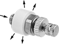
Slow-Start Air-Exhaust Valves for Wilkerson Modular
Compressed Air Filter/Regulator/Lubricators (FRLs)
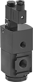
Also known as Monday-morning valves, these valves slowly introduce pressure to reduce surge damage during start-up. When the solenoid is shut off, the valve cuts air to your equipment by exhausting downstream pressure. To ensure compatibility, the valve series number should match the series number on your Wilkerson components.
![]() For technical drawings and 3-D models, click on a part number.
For technical drawings and 3-D models, click on a part number.
Pipe Size | Valve | Overall | |||||||||||
|---|---|---|---|---|---|---|---|---|---|---|---|---|---|
| Manufacturer Series | Inlet | Outlet | Exhaust | Type | Starting Position | Max. Flow Rate | Max. Pressure, psi | Temperature Range, °F | Ht. | Wd. | Dp. | Each | |
120V AC | |||||||||||||
NPT Female Inlet, Outlet, and Exhaust | |||||||||||||
Series No. 18 | |||||||||||||
| E18 | 1/4 | 1/4 | 3/8 | Poppet | Normally Closed | 80 scfm @ 100 psi | 150 | 32° to 150° | 7 3/8" | 2 3/4" | 2 3/8" | 0000000 | 0000000 |
| E18 | 3/8 | 3/8 | 3/8 | Poppet | Normally Closed | 90 scfm @ 100 psi | 150 | 32° to 150° | 7 3/8" | 2 3/4" | 2 3/8" | 0000000 | 000000 |
| E18 | 1/2 | 1/2 | 3/8 | Poppet | Normally Closed | 95 scfm @ 100 psi | 150 | 32° to 150° | 7 3/8" | 2 3/4" | 2 3/8" | 0000000 | 000000 |
Series No. 28 | |||||||||||||
| E28 | 3/8 | 3/8 | 3/8 | Spool | Normally Closed | 196 scfm @ 100 psi | 150 | 32° to 150° | 7 3/8" | 3" | 2 7/8" | 0000000 | 000000 |
| E28 | 1/2 | 1/2 | 3/8 | Spool | Normally Closed | 210 scfm @ 100 psi | 150 | 32° to 150° | 7 3/8" | 3" | 2 7/8" | 0000000 | 000000 |
| E28 | 3/4 | 3/4 | 3/8 | Spool | Normally Closed | 230 scfm @ 100 psi | 150 | 32° to 150° | 7 3/8" | 3" | 2 7/8" | 0000000 | 000000 |
24V DC | |||||||||||||
NPT Female Inlet, Outlet, and Exhaust | |||||||||||||
Series No. 18 | |||||||||||||
| E18 | 1/4 | 1/4 | 3/8 | Poppet | Normally Closed | 80 scfm @ 100 psi | 150 | 32° to 150° | 7 3/8" | 2 3/4" | 2 3/8" | 0000000 | 000000 |
| E18 | 3/8 | 3/8 | 3/8 | Poppet | Normally Closed | 90 scfm @ 100 psi | 150 | 32° to 150° | 7 3/8" | 2 3/4" | 2 3/8" | 0000000 | 000000 |
| E18 | 1/2 | 1/2 | 3/8 | Poppet | Normally Closed | 95 scfm @ 100 psi | 150 | 32° to 150° | 7 3/8" | 2 3/4" | 2 3/8" | 0000000 | 000000 |
Series No. 28 | |||||||||||||
| E28 | 3/8 | 3/8 | 3/8 | Spool | Normally Closed | 196 scfm @ 100 psi | 150 | 32° to 150° | 7 3/8" | 3" | 2 7/8" | 0000000 | 000000 |
| E28 | 1/2 | 1/2 | 3/8 | Spool | Normally Closed | 210 scfm @ 100 psi | 150 | 32° to 150° | 7 3/8" | 3" | 2 7/8" | 0000000 | 000000 |
| E28 | 3/4 | 3/4 | 3/8 | Spool | Normally Closed | 230 scfm @ 100 psi | 150 | 32° to 150° | 7 3/8" | 3" | 2 7/8" | 0000000 | 000000 |
Slow-Start Air-Exhaust Valves for SMC Modular
Compressed Air Filter/Regulator/Lubricators (FRLs)
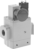
Also known as Monday-morning valves, these valves slowly introduce pressure to reduce surge damage during start-up. When the solenoid is shut off, the valve cuts air to your equipment by exhausting downstream pressure. To ensure compatibility, the valve series number should match the series number on your SMC components.
![]() For technical drawings and 3-D models, click on a part number.
For technical drawings and 3-D models, click on a part number.
Pipe Size | Valve | Overall | |||||||||||
|---|---|---|---|---|---|---|---|---|---|---|---|---|---|
| Manufacturer Series | Inlet | Outlet | Exhaust | Type | Starting Position | Max. Flow Rate | Max. Pressure, psi | Temperature Range, °F | Ht. | Wd. | Dp. | Each | |
120V AC | |||||||||||||
NPT Female Inlet, Outlet, and Exhaust | |||||||||||||
Series No. 50 | |||||||||||||
| AVL5000 | 3/4 | 3/4 | 3/4 | Spool | Normally Closed | 250 scfm @ 100 psi | 145 | 32° to 140° | 7 3/4" | 5 1/8" | 2 15/16" | 0000000 | 0000000 |
| AVL5000 | 1 | 1 | 1 | Spool | Normally Closed | 270 scfm @ 100 psi | 145 | 32° to 140° | 7 3/4" | 5 1/8" | 2 15/16" | 0000000 | 000000 |
24V DC | |||||||||||||
NPT Female Inlet, Outlet, and Exhaust | |||||||||||||
Series No. 50 | |||||||||||||
| AVL5000 | 3/4 | 3/4 | 3/4 | Spool | Normally Closed | 250 scfm @ 100 psi | 145 | 32° to 140° | 7 3/4" | 5 1/8" | 2 15/16" | 0000000 | 000000 |
| AVL5000 | 1 | 1 | 1 | Spool | Normally Closed | 270 scfm @ 100 psi | 145 | 32° to 140° | 7 3/4" | 5 1/8" | 2 15/16" | 0000000 | 000000 |