


Filter by
Valve Type
Body Material


For Use With
Fitting Connection

Actuation Type
Seat Material
Actuation Mechanism
Disc Material
Valve Function


Mounting Position
Maximum Pressure @ Temperature
Maximum Temperature
U.S.–Mexico–Canada Agreement (USMCA) Qualifying
Export Control Classification Number (ECCN)
REACH
DFARS Specialty Metals
About Actuated On/Off Valves
Choose the right automatic on/off valve based on power source, pressure, and flow rate.
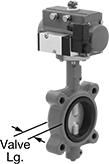
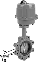
Flanged Air-Driven On/Off Valves
 |  |
4 Bolt Holes | 8 Bolt Holes |
To automatically start and stop flow faster than motor-driven valves, these operate on compressed air. You must control the air to the actuator using either the included electric pilot valve or a manual on/off valve (not included). Valves don’t require a minimum pressure drop between the inlet and outlet for operation.
The actuator is directly mounted to the valve body to minimize movement and reduce wear. A visual flow indicator on the top of the actuator shows whether the valve is open or closed. The manual override allows you to operate the valve during power outages. Valves meet NSF/ANSI 61 for use with drinking water.
All valves are lug style; their hole pattern matches ANSI flanges of the same pipe size. They can be sandwiched between two flanges, or bolt them directly to a single flange for servicing one end of the pipeline without depressurizing the other side.
Single Acting—Single-acting actuators only require air pressure to open the valve; they automatically spring closed when the air turns off. These valves are fail closed unless actuated.
Double Acting—Double-acting actuators require air pressure to open and close the valve. Once actuated, these valves remain actuated until air pressure is applied, so they do not have a valve starting position.
Flow Coefficient (Cv)—Flow coefficient (Cv) is the amount of water (in gallons per minute) at 60° F that will flow through a fully open valve with a difference of 1 psi between the inlet and the outlet.
Bolts | Air | |||||||||||||||||||
|---|---|---|---|---|---|---|---|---|---|---|---|---|---|---|---|---|---|---|---|---|
Pipe Size | Flange OD | No. of Holes | Hole Size | Included | Circle Dia. | Flow Coefficient (Cv) | Max. Pressure @ Temp. | Valve Type | Temp. Range, ° F | Valve Lg. | Overall Ht. | Connection | Min. Pressure, psi | Max. Pressure, psi | Specs. Met | Food Industry Std. | Each | |||
Ductile Iron Body with Screw Terminals | ||||||||||||||||||||
Single Acting: Air-to-Open, Spring Return (Fail Closed)—120V AC | ||||||||||||||||||||
| 2 | 6" | 4 | 5/8" | No | 4 3/4" | 135 | 250 psi @ 100° F | Butterfly, Zero Pressure Drop | -30 to 250 | 1 5/8" | 14 1/8" | 1/4 NPT Female | 40 | 115 | API Std 609 | NSF/ANSI 61 | 2522N15 | 0000000 | ||
| 3 | 7 1/2" | 4 | 5/8" | No | 6" | 300 | 250 psi @ 100° F | Butterfly, Zero Pressure Drop | -30 to 250 | 1 3/4" | 15 15/16" | 1/4 NPT Female | 40 | 115 | API Std 609 | NSF/ANSI 61 | 2522N16 | 000000 | ||
| 4 | 9" | 8 | 5/8" | No | 7 1/2" | 605 | 250 psi @ 100° F | Butterfly, Zero Pressure Drop | -30 to 250 | 2 1/16" | 17 15/16" | 1/4 NPT Female | 40 | 115 | API Std 609 | NSF/ANSI 61 | 2522N17 | 000000 | ||
| 6 | 11" | 8 | 3/4" | No | 9 1/2" | 1,620 | 250 psi @ 100° F | Butterfly, Zero Pressure Drop | -30 to 250 | 2 3/16" | 22 1/2" | 1/4 NPT Female | 40 | 115 | API Std 609 | NSF/ANSI 61 | 2522N18 | 00000000 | ||
Double Acting: Air-to-Open, Air-to-Close—120V AC | ||||||||||||||||||||
| 2 | 6" | 4 | 5/8" | No | 4 3/4" | 135 | 250 psi @ 100° F | Butterfly, Zero Pressure Drop | -30 to 250 | 1 5/8" | 13" | 1/4 NPT Female | 40 | 115 | API Std 609 | NSF/ANSI 61 | 2522N11 | 000000 | ||
| 3 | 7 1/2" | 4 | 5/8" | No | 6" | 300 | 250 psi @ 100° F | Butterfly, Zero Pressure Drop | -30 to 250 | 1 3/4" | 14 13/16" | 1/4 NPT Female | 40 | 115 | API Std 609 | NSF/ANSI 61 | 2522N12 | 000000 | ||
| 4 | 9" | 8 | 5/8" | No | 7 1/2" | 605 | 250 psi @ 100° F | Butterfly, Zero Pressure Drop | -30 to 250 | 2 1/16" | 17" | 1/4 NPT Female | 40 | 115 | API Std 609 | NSF/ANSI 61 | 2522N13 | 000000 | ||
| 6 | 11" | 8 | 3/4" | No | 9 1/2" | 1,620 | 250 psi @ 100° F | Butterfly, Zero Pressure Drop | -30 to 250 | 2 3/16" | 19 15/16" | 1/4 NPT Female | 40 | 115 | API Std 609 | NSF/ANSI 61 | 2522N14 | 000000 | ||
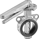
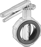
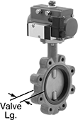
Lightweight Flanged Flow-Adjustment Valves
 |  |
4 Bolt Holes | 8 Bolt Holes |
An aluminum body provides strength and durability at half the weight of other metal flanged flow-adjustment valves. These valves bolt to flanges for adjusting and regulating flow in flanged pipelines. Fix the lockable lever handle in place using a padlock (not included) with a shackle diameter up to 5/16”. Valves are wafer style, so they must be sandwiched between two flanges; all have unthreaded holes or tabs to help align the valve between the flanges.
Flow Coefficient (Cv)—Flow coefficient (Cv) is the amount of water (in gallons per minute) at 60° F that will flow through a fully open valve with a difference of 1 psi between the inlet and the outlet.
Pipe Size | For Use With | For Max. Shackle Dia. | Pressure Class | Flange OD | Bolt Circle Dia. | No. of Bolt Holes | Bolt Hole Size | Bolts Included | Flow Coefficient (Cv) | Max. Pressure @ Temp. | Temp. Range, ° F | End-to-End Lg. | Valve Type | Each | |||
|---|---|---|---|---|---|---|---|---|---|---|---|---|---|---|---|---|---|
Aluminum Body—316 Stainless Steel Disc | |||||||||||||||||
| 2 | Water, Oil, Air | 3/16" | 125, 150 | 6" | 4 3/4" | 4 | 3/4" | No | 220 | 150 psi @ 210° F | 0 to 210 | 1 15/16" | Butterfly | 4850K21 | 0000000 | ||
| 2 | Water, Air | 3/16" | 125, 150 | 6" | 4 3/4" | 4 | 3/4" | No | 220 | 150 psi @ 250° F | -40 to 250 | 1 15/16" | Butterfly | 4850K31 | 000000 | ||
| 3 | Water, Oil, Air | 3/16" | 125, 150 | 7 1/2" | 6" | 4 | 3/4" | No | 500 | 150 psi @ 210° F | 0 to 210 | 2" | Butterfly | 4850K22 | 000000 | ||
| 3 | Water, Air | 3/16" | 125, 150 | 7 1/2" | 6" | 4 | 3/4" | No | 500 | 150 psi @ 250° F | -40 to 250 | 2" | Butterfly | 4850K32 | 000000 | ||
| 4 | Water, Oil, Air | 3/16" | 125, 150 | 9" | 7 1/2" | 8 | 3/4" | No | 820 | 150 psi @ 210° F | 0 to 210 | 2 1/4" | Butterfly | 4850K23 | 000000 | ||
| 4 | Water, Air | 3/16" | 125, 150 | 9" | 7 1/2" | 8 | 3/4" | No | 820 | 150 psi @ 250° F | -40 to 250 | 2 1/4" | Butterfly | 4850K33 | 000000 | ||
| 6 | Water, Oil, Air | 3/16" | 125, 150 | 11" | 9 1/2" | 8 | 0.88" | No | 1,900 | 150 psi @ 210° F | 0 to 210 | 2 3/8" | Butterfly | 4850K24 | 000000 | ||
| 6 | Water, Air | 3/16" | 125, 150 | 11" | 9 1/2" | 8 | 0.88" | No | 1,900 | 150 psi @ 250° F | -40 to 250 | 2 3/8" | Butterfly | 4850K34 | 000000 | ||
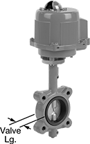
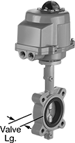
Flanged Motor-Actuated On/Off Valves
Ductile Iron Body with Screw-Terminal Wire Connection
 |  |
4 Bolt Holes | 8 Bolt Holes |
With Manual Override—Valves with a manual override can be operated during power outages.
Flow Coefficient (Cv)—Flow coefficient (Cv) is the amount of water (in gallons per minute) at 60° F that will flow through a fully open valve with a difference of 1 psi between the inlet and the outlet.
Bolts | Overall | ||||||||||||||||||||||
|---|---|---|---|---|---|---|---|---|---|---|---|---|---|---|---|---|---|---|---|---|---|---|---|
Pipe Size | Fitting Connection | Port Type | Flange OD | No. of Holes | Hole Size | Included | Circle Dia. | Flow Coefficient (Cv) | Max. Pressure @ Temp. | Max. Steam Pressure @ Temp. | Manual Override | Valve Type | Actuation Time, sec. | Temp. Range, ° F | Valve Lg. | Lg. | Ht. | Specs. Met | Food Industry Std. | Each | |||
Fail in Place—24V AC/24V DC | |||||||||||||||||||||||
| 2 | Flanged | Full | 6" | 4 | 5/8" | No | 4 3/4" | 135 | 250 psi @ 100° F | Not Rated | Yes | Butterfly Zero Pressure Drop | 8 | -30 to 250 | 1 5/8" | 7 3/8" | 17 5/16" | API Std 609 | NSF/ANSI 61 | 2521N15 | 0000000 | ||
| 3 | Flanged | Full | 7 1/2" | 4 | 5/8" | No | 6" | 300 | 250 psi @ 100° F | Not Rated | Yes | Butterfly Zero Pressure Drop | 8 | -30 to 250 | 1 3/4" | 7 3/8" | 18 11/16" | API Std 609 | NSF/ANSI 61 | 2521N16 | 000000 | ||
| 4 | Flanged | Full | 9" | 8 | 5/8" | No | 7 1/2" | 605 | 250 psi @ 100° F | Not Rated | Yes | Butterfly Zero Pressure Drop | 9 | -30 to 250 | 2 1/16" | 7 3/4" | 21" | API Std 609 | NSF/ANSI 61 | 2521N17 | 00000000 | ||
| 6 | Flanged | Full | 11" | 8 | 3/4" | No | 9 1/2" | 1,620 | 250 psi @ 100° F | Not Rated | Yes | Butterfly Zero Pressure Drop | 27 | -30 to 250 | 2 3/16" | 10 1/2" | 24 1/16" | API Std 609 | NSF/ANSI 61 | 2521N18 | 00000000 | ||
Fail in Place—120V AC | |||||||||||||||||||||||
| 2 | Flanged | Full | 6" | 4 | 5/8" | No | 4 3/4" | 135 | 250 psi @ 100° F | Not Rated | Yes | Butterfly Zero Pressure Drop | 8 | -30 to 250 | 1 5/8" | 7 3/8" | 17 5/16" | API Std 609 | NSF/ANSI 61 | 2521N11 | 000000 | ||
| 3 | Flanged | Full | 7 1/2" | 4 | 5/8" | No | 6" | 300 | 250 psi @ 100° F | Not Rated | Yes | Butterfly Zero Pressure Drop | 8 | -30 to 250 | 1 3/4" | 7 3/8" | 18 11/16" | API Std 609 | NSF/ANSI 61 | 2521N12 | 000000 | ||
| 4 | Flanged | Full | 9" | 8 | 5/8" | No | 7 1/2" | 605 | 250 psi @ 100° F | Not Rated | Yes | Butterfly Zero Pressure Drop | 9 | -30 to 250 | 2 1/16" | 7 3/4" | 21" | API Std 609 | NSF/ANSI 61 | 2521N13 | 00000000 | ||
| 6 | Flanged | Full | 11" | 8 | 3/4" | No | 9 1/2" | 1,620 | 250 psi @ 100° F | Not Rated | Yes | Butterfly Zero Pressure Drop | 27 | -30 to 250 | 2 3/16" | 10 1/2" | 24 1/16" | API Std 609 | NSF/ANSI 61 | 2521N14 | 00000000 | ||
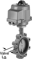
Air-Driven On/Off Valves for Fuel
 |  |
4 Bolt Holes | 8 Bolt Holes |
Use these valves to safely transfer fuel and oil. They operate on compressed air to automatically start and stop flow faster than motor-driven valves. You must control the air to the actuator using either the included electric pilot valve or a manual on/off valve (not included). These valves don’t require a minimum pressure drop between the inlet and outlet for operation.
The actuator is directly mounted to the valve body to minimize movement and reduce wear. A visual flow indicator on the top of the actuator shows whether the valve is open or closed. The manual override allows you to operate the valve during power outages.
All valves are lug style; their hole pattern matches ANSI flanges of the same pipe size. They can be sandwiched between two flanges, or bolt them directly to a single flange for servicing one end of the pipeline without depressurizing the other side.
Single Acting—Single-acting actuators only require air pressure to open the valve; they automatically spring closed when the air turns off. These valves are fail closed unless actuated.
Double Acting—Double-acting actuators require air pressure to open and close the valve. Once actuated, these valves remain actuated until air pressure is applied, so they do not have a valve starting position.
Flow Coefficient (Cv)—Flow coefficient (Cv) is the amount of water (in gallons per minute) at 60° F that will flow through a fully open valve with a difference of 1 psi between the inlet and the outlet.
Bolts | Overall | Air | ||||||||||||||||||||
|---|---|---|---|---|---|---|---|---|---|---|---|---|---|---|---|---|---|---|---|---|---|---|
Pipe Size | Flange OD | No. of Holes | Hole Size | Included | Circle Dia. | Fitting Connection | Flow Coefficient (Cv) | Max. Pressure @ Temp. | Valve Type | Temp. Range, ° F | Valve Lg. | Lg. | Ht. | Connection | Min. Pressure, psi | Max. Pressure, psi | Fasteners Included | Specs. Met | Each | |||
Ductile Iron Body with Screw Terminals | ||||||||||||||||||||||
Single Acting: Air-to-Open, Spring Return (Fail Closed)—120V AC | ||||||||||||||||||||||
| 2 | 6" | 4 | 5/8" | No | 4 3/4" | Flanged | 135 | 250 psi @ 100° F | Butterfly, Zero Pressure Drop | 10 to 350 | 1 5/8" | 8 1/4" | 14 5/8" | 1/4 NPT Female | 40 | 115 | Yes | API Std 609, MSS SP-67 | 2529N15 | 0000000 | ||
| 3 | 7 1/2" | 4 | 5/8" | No | 6" | Flanged | 300 | 250 psi @ 100° F | Butterfly, Zero Pressure Drop | 10 to 350 | 1 3/4" | 9 1/2" | 16 9/16" | 1/4 NPT Female | 40 | 115 | Yes | API Std 609, MSS SP-67 | 2529N16 | 000000 | ||
| 4 | 9" | 8 | 5/8" | No | 7 1/2" | Flanged | 605 | 250 psi @ 100° F | Butterfly, Zero Pressure Drop | 10 to 350 | 2 1/16" | 10 13/16" | 18 9/16" | 1/4 NPT Female | 40 | 115 | Yes | API Std 609, MSS SP-67 | 2529N17 | 00000000 | ||
| 6 | 11" | 8 | 3/4" | No | 9 1/2" | Flanged | 1,620 | 250 psi @ 100° F | Butterfly, Zero Pressure Drop | 10 to 350 | 2 3/16" | 14 5/8" | 23 5/16" | 1/4 NPT Female | 40 | 115 | Yes | API Std 609, MSS SP-67 | 2529N18 | 00000000 | ||
Double Acting: Air-to-Open, Air-to-Close—120V AC | ||||||||||||||||||||||
| 2 | 6" | 4 | 5/8" | No | 4 3/4" | Flanged | 135 | 250 psi @ 100° F | Butterfly, Zero Pressure Drop | 10 to 350 | 1 5/8" | 5 9/16" | 13 1/2" | 1/4 NPT Female | 40 | 115 | Yes | API Std 609, MSS SP-67 | 2529N11 | 000000 | ||
| 3 | 7 1/2" | 4 | 5/8" | No | 6" | Flanged | 300 | 250 psi @ 100° F | Butterfly, Zero Pressure Drop | 10 to 350 | 1 3/4" | 6 7/16" | 15 5/16" | 1/4 NPT Female | 40 | 115 | Yes | API Std 609, MSS SP-67 | 2529N12 | 000000 | ||
| 4 | 9" | 8 | 5/8" | No | 7 1/2" | Flanged | 605 | 250 psi @ 100° F | Butterfly, Zero Pressure Drop | 10 to 350 | 2 1/16" | 8 1/4" | 17 1/2" | 1/4 NPT Female | 40 | 115 | Yes | API Std 609, MSS SP-67 | 2529N13 | 000000 | ||
| 6 | 11" | 8 | 3/4" | No | 9 1/2" | Flanged | 1,620 | 250 psi @ 100° F | Butterfly, Zero Pressure Drop | 10 to 350 | 2 3/16" | 9 1/2" | 20 9/16" | 1/4 NPT Female | 40 | 115 | Yes | API Std 609, MSS SP-67 | 2529N14 | 00000000 | ||
Motor-Actuated On/Off Valves for Fuel
Ductile Iron Body with Screw-Terminal Wire Connection
 |  |
4 Bolt Holes | 8 Bolt Holes |
Flow Coefficient (Cv)—Flow coefficient (Cv) is the amount of water (in gallons per minute) at 60° F that will flow through a fully open valve with a difference of 1 psi between the inlet and the outlet.
Bolts | Overall | |||||||||||||||||||
|---|---|---|---|---|---|---|---|---|---|---|---|---|---|---|---|---|---|---|---|---|
Pipe Size | Fitting Connection | Flange OD | No. of Holes | Hole Size | Included | Circle Dia. | Flow Coefficient (Cv) | Max. Pressure @ Temp. | Manual Override | Valve Type | Actuation Time, sec. | Temp. Range, ° F | Valve Lg. | Lg. | Ht. | Specs. Met | Each | |||
Fail in Place—24V AC/24V DC | ||||||||||||||||||||
| 2 | Flanged | 6" | 4 | 5/8" | No | 4 3/4" | 135 | 250 psi @ 100° F | Yes | Butterfly Zero Pressure Drop | 8 | 10 to 350 | 1 5/8" | 7 3/8" | 17 13/16" | API Std 609, MSS SP-67 | 2524N15 | 0000000 | ||
| 3 | Flanged | 7 1/2" | 4 | 5/8" | No | 6" | 300 | 250 psi @ 100° F | Yes | Butterfly Zero Pressure Drop | 8 | 10 to 350 | 1 3/4" | 7 3/8" | 19 3/16" | API Std 609, MSS SP-67 | 2524N16 | 000000 | ||
| 4 | Flanged | 9" | 8 | 5/8" | No | 7 1/2" | 605 | 250 psi @ 100° F | Yes | Butterfly Zero Pressure Drop | 9 | 10 to 350 | 2 1/16" | 7 3/4" | 21 5/8" | API Std 609, MSS SP-67 | 2524N17 | 00000000 | ||
| 6 | Flanged | 11" | 8 | 3/4" | No | 9 1/2" | 1,620 | 250 psi @ 100° F | Yes | Butterfly Zero Pressure Drop | 27 | 10 to 350 | 2 3/16" | 10 1/2" | 27 7/16" | API Std 609, MSS SP-67 | 2524N18 | 00000000 | ||
Fail in Place—120V AC | ||||||||||||||||||||
| 2 | Flanged | 6" | 4 | 5/8" | No | 4 3/4" | 135 | 250 psi @ 100° F | Yes | Butterfly Zero Pressure Drop | 8 | 10 to 350 | 1 5/8" | 7 3/8" | 17 13/16" | API Std 609, MSS SP-67 | 2524N11 | 000000 | ||
| 3 | Flanged | 7 1/2" | 4 | 5/8" | No | 6" | 300 | 250 psi @ 100° F | Yes | Butterfly Zero Pressure Drop | 8 | 10 to 350 | 1 3/4" | 7 3/8" | 19 3/16" | API Std 609, MSS SP-67 | 2524N12 | 000000 | ||
| 4 | Flanged | 9" | 8 | 5/8" | No | 7 1/2" | 605 | 250 psi @ 100° F | Yes | Butterfly Zero Pressure Drop | 9 | 10 to 350 | 2 1/16" | 7 3/4" | 21 5/8" | API Std 609, MSS SP-67 | 2524N13 | 00000000 | ||
| 6 | Flanged | 11" | 8 | 3/4" | No | 9 1/2" | 1,620 | 250 psi @ 100° F | Yes | Butterfly Zero Pressure Drop | 27 | 10 to 350 | 2 3/16" | 10 1/2" | 27 7/16" | API Std 609, MSS SP-67 | 2524N14 | 00000000 | ||
