Filter by
Pipe Material
Fitting Connection


Flanged Connection Surface
Fitting Material
For Use With
Pipe Schedule


Length
Shape
Export Control Classification Number (ECCN)
DFARS Specialty Metals
Flange Material

About Pipe and Fittings
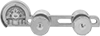
Measure your pipe and fittings to identify their pipe size, thread size, schedule, and thread type. Then, find compatible components.
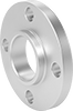
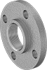
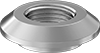
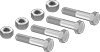
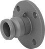
Pipe and Fittings
Aluminum Unthreaded Pipe and Fittings