


Filter by
Weight Capacity
DC Voltage
Load Connection Thread Size
AC Current
Height
Width
DC Current
Weight Measuring Increments
DFARS Specialty Metals
Electrical Connection

Load Sensor Connection
Sensor Material
Data Connection
Analog Electrical Panel Meters
Measures AC Voltage
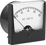 |
EMI Resistance—Meters with electromagnetic interference (EMI) resistance are shielded to prevent interference and maintain accuracy when mounted on a magnetic panel.
For Panel Cutout | Input | ||||||||||||||||||||||||||||||||||||||||||||||||||||||||||||||||||||||||||||||||||||||||||||||||||
|---|---|---|---|---|---|---|---|---|---|---|---|---|---|---|---|---|---|---|---|---|---|---|---|---|---|---|---|---|---|---|---|---|---|---|---|---|---|---|---|---|---|---|---|---|---|---|---|---|---|---|---|---|---|---|---|---|---|---|---|---|---|---|---|---|---|---|---|---|---|---|---|---|---|---|---|---|---|---|---|---|---|---|---|---|---|---|---|---|---|---|---|---|---|---|---|---|---|---|---|
AC Voltage, V AC | Accuracy | Ht. | Wd. | Dp. | Electrical Features | Dia. | Dp. | Wire Connection | Resistance, ohm | Frequency, Hz | Freq. Calibration, Hz | Each | |||||||||||||||||||||||||||||||||||||||||||||||||||||||||||||||||||||||||||||||||||||||
Acrylic Plastic Window | |||||||||||||||||||||||||||||||||||||||||||||||||||||||||||||||||||||||||||||||||||||||||||||||||||
| 0 to 50 | ±2% | 3.25" | 3.25" | 2.54" | EMI Resistance | 2.79" | 1.92" | Screw Terminal | 3,333 | 25 to 125 | 60 | 7107K513 | 0000000 | ||||||||||||||||||||||||||||||||||||||||||||||||||||||||||||||||||||||||||||||||||||||
| 0 to 150 | ±2% | 2.47" | 2.47" | 2.33" | EMI Resistance | 2.22" | 1.85" | Screw Terminal | 25,000 | 25 to 125 | 60 | 7107K113 | 000000 | ||||||||||||||||||||||||||||||||||||||||||||||||||||||||||||||||||||||||||||||||||||||
| 0 to 150 | ±2% | 3.25" | 3.25" | 2.54" | EMI Resistance | 2.79" | 1.92" | Screw Terminal | 25,000 | 25 to 125 | 60 | 7107K117 | 000000 | ||||||||||||||||||||||||||||||||||||||||||||||||||||||||||||||||||||||||||||||||||||||
| 0 to 300 | ±2% | 2.47" | 2.47" | 2.33" | EMI Resistance | 2.22" | 1.85" | Screw Terminal | 50,000 | 25 to 125 | 60 | 7107K512 | 000000 | ||||||||||||||||||||||||||||||||||||||||||||||||||||||||||||||||||||||||||||||||||||||
| 0 to 300 | ±2% | 3.25" | 3.25" | 2.54" | EMI Resistance | 2.79" | 1.92" | Screw Terminal | 50,000 | 25 to 125 | 60 | 7107K118 | 000000 | ||||||||||||||||||||||||||||||||||||||||||||||||||||||||||||||||||||||||||||||||||||||
Glass Window | |||||||||||||||||||||||||||||||||||||||||||||||||||||||||||||||||||||||||||||||||||||||||||||||||||
| 0 to 50 | ±2% | 3" | 3" | 2.56" | EMI Resistance | 2.83" | 2.05" | Screw Terminal | 3,333 | 25 to 125 | 60 | 7107K314 | 000000 | ||||||||||||||||||||||||||||||||||||||||||||||||||||||||||||||||||||||||||||||||||||||
| 0 to 150 | ±2% | 2.38" | 2.38" | 2.68" | EMI Resistance | 2.22" | 2.17" | Screw Terminal | 25,000 | 25 to 125 | 60 | 7107K311 | 000000 | ||||||||||||||||||||||||||||||||||||||||||||||||||||||||||||||||||||||||||||||||||||||
| 0 to 150 | ±2% | 3" | 3" | 2.56" | EMI Resistance | 2.83" | 2.05" | Screw Terminal | 25,000 | 25 to 125 | 60 | 7107K315 | 000000 | ||||||||||||||||||||||||||||||||||||||||||||||||||||||||||||||||||||||||||||||||||||||
| 0 to 300 | ±2% | 2.38" | 2.38" | 2.68" | EMI Resistance | 2.22" | 2.17" | Screw Terminal | 50,000 | 25 to 125 | 60 | 7107K312 | 000000 | ||||||||||||||||||||||||||||||||||||||||||||||||||||||||||||||||||||||||||||||||||||||
| 0 to 300 | ±2% | 3" | 3" | 2.56" | EMI Resistance | 2.83" | 2.05" | Screw Terminal | 50,000 | 25 to 125 | 60 | 7107K316 | 000000 | ||||||||||||||||||||||||||||||||||||||||||||||||||||||||||||||||||||||||||||||||||||||
Measures DC Voltage
|
EMI Resistance—Meters with electromagnetic interference (EMI) resistance are shielded to prevent interference and maintain accuracy when mounted on a magnetic panel.
For Panel Cutout | |||||||||||||||||||||||||||||||||||||||||||||||||||||||||||||||||||||||||||||||||||||||||||||||||||
|---|---|---|---|---|---|---|---|---|---|---|---|---|---|---|---|---|---|---|---|---|---|---|---|---|---|---|---|---|---|---|---|---|---|---|---|---|---|---|---|---|---|---|---|---|---|---|---|---|---|---|---|---|---|---|---|---|---|---|---|---|---|---|---|---|---|---|---|---|---|---|---|---|---|---|---|---|---|---|---|---|---|---|---|---|---|---|---|---|---|---|---|---|---|---|---|---|---|---|---|
DC Voltage, V DC | Accuracy | Ht. | Wd. | Dp. | Electrical Features | Dia. | Dp. | Wire Connection | Input Resistance, ohm | Each | |||||||||||||||||||||||||||||||||||||||||||||||||||||||||||||||||||||||||||||||||||||||||
Acrylic Plastic Window | |||||||||||||||||||||||||||||||||||||||||||||||||||||||||||||||||||||||||||||||||||||||||||||||||||
| 0 to 10 | ±2% | 1.76" | 1.75" | 1.82" | EMI Resistance | 1.55" | 1.41" | Screw Terminal | 1,000 | 7107K319 | 0000000 | ||||||||||||||||||||||||||||||||||||||||||||||||||||||||||||||||||||||||||||||||||||||||
| 0 to 10 | ±2% | 3.25" | 3.25" | 2.54" | EMI Resistance | 2.79" | 1.92" | Screw Terminal | 1,000 | 7107K18 | 000000 | ||||||||||||||||||||||||||||||||||||||||||||||||||||||||||||||||||||||||||||||||||||||||
| 0 to 15 | ±2% | 1.76" | 1.75" | 1.82" | EMI Resistance | 1.55" | 1.41" | Screw Terminal | 1,000 | 7107K321 | 000000 | ||||||||||||||||||||||||||||||||||||||||||||||||||||||||||||||||||||||||||||||||||||||||
| 0 to 15 | ±2% | 3.25" | 3.25" | 2.54" | EMI Resistance | 2.79" | 1.92" | Screw Terminal | 1,000 | 7107K21 | 000000 | ||||||||||||||||||||||||||||||||||||||||||||||||||||||||||||||||||||||||||||||||||||||||
| 0 to 30 | ±2% | 1.76" | 1.75" | 1.82" | EMI Resistance | 1.55" | 1.41" | Screw Terminal | 1,000 | 7107K322 | 000000 | ||||||||||||||||||||||||||||||||||||||||||||||||||||||||||||||||||||||||||||||||||||||||
| 0 to 30 | ±2% | 3.25" | 3.25" | 2.54" | EMI Resistance | 2.79" | 1.92" | Screw Terminal | 1,000 | 7107K23 | 000000 | ||||||||||||||||||||||||||||||||||||||||||||||||||||||||||||||||||||||||||||||||||||||||
| 0 to 100 | ±2% | 1.76" | 1.75" | 1.82" | EMI Resistance | 1.55" | 1.41" | Screw Terminal | 1,000 | 7107K323 | 000000 | ||||||||||||||||||||||||||||||||||||||||||||||||||||||||||||||||||||||||||||||||||||||||
| 0 to 100 | ±2% | 3.25" | 3.25" | 2.54" | EMI Resistance | 2.79" | 1.92" | Screw Terminal | 1,000 | 7107K25 | 000000 | ||||||||||||||||||||||||||||||||||||||||||||||||||||||||||||||||||||||||||||||||||||||||
| 0 to 150 | ±2% | 3.25" | 3.25" | 2.54" | EMI Resistance | 2.79" | 1.92" | Screw Terminal | 1,000 | 7107K27 | 000000 | ||||||||||||||||||||||||||||||||||||||||||||||||||||||||||||||||||||||||||||||||||||||||
Glass Window | |||||||||||||||||||||||||||||||||||||||||||||||||||||||||||||||||||||||||||||||||||||||||||||||||||
| 0 to 10 | ±2% | 1.75" | 1.75" | 1.81" | EMI Resistance | 1.56" | 1.43" | Screw Terminal | 1,000 | 7107K71 | 000000 | ||||||||||||||||||||||||||||||||||||||||||||||||||||||||||||||||||||||||||||||||||||||||
| 0 to 10 | ±2% | 3" | 3" | 2.56" | EMI Resistance | 2.83" | 2.05" | Screw Terminal | 1,000 | 7107K72 | 000000 | ||||||||||||||||||||||||||||||||||||||||||||||||||||||||||||||||||||||||||||||||||||||||
| 0 to 15 | ±2% | 1.75" | 1.75" | 1.81" | EMI Resistance | 1.56" | 1.43" | Screw Terminal | 1,000 | 7107K12 | 000000 | ||||||||||||||||||||||||||||||||||||||||||||||||||||||||||||||||||||||||||||||||||||||||
| 0 to 15 | ±2% | 3" | 3" | 2.56" | EMI Resistance | 2.83" | 2.05" | Screw Terminal | 1,000 | 7107K31 | 000000 | ||||||||||||||||||||||||||||||||||||||||||||||||||||||||||||||||||||||||||||||||||||||||
| 0 to 30 | ±2% | 1.75" | 1.75" | 1.81" | EMI Resistance | 1.56" | 1.43" | Screw Terminal | 1,000 | 7107K13 | 000000 | ||||||||||||||||||||||||||||||||||||||||||||||||||||||||||||||||||||||||||||||||||||||||
| 0 to 30 | ±2% | 3" | 3" | 2.56" | EMI Resistance | 2.83" | 2.05" | Screw Terminal | 1,000 | 7107K32 | 000000 | ||||||||||||||||||||||||||||||||||||||||||||||||||||||||||||||||||||||||||||||||||||||||
| 0 to 100 | ±2% | 1.75" | 1.75" | 1.81" | EMI Resistance | 1.56" | 1.43" | Screw Terminal | 1,000 | 7107K73 | 000000 | ||||||||||||||||||||||||||||||||||||||||||||||||||||||||||||||||||||||||||||||||||||||||
| 0 to 100 | ±2% | 3" | 3" | 2.56" | EMI Resistance | 2.83" | 2.05" | Screw Terminal | 1,000 | 7107K324 | 000000 | ||||||||||||||||||||||||||||||||||||||||||||||||||||||||||||||||||||||||||||||||||||||||
| 0 to 150 | ±2% | 3" | 3" | 2.56" | EMI Resistance | 2.83" | 2.05" | Screw Terminal | 1,000 | 7107K33 | 000000 | ||||||||||||||||||||||||||||||||||||||||||||||||||||||||||||||||||||||||||||||||||||||||
Measures AC Current
|
For Panel Cutout | Input | ||||||||||||||||||||||||||||||||||||||||||||||||||||||||||||||||||||||||||||||||||||||||||||||||||
|---|---|---|---|---|---|---|---|---|---|---|---|---|---|---|---|---|---|---|---|---|---|---|---|---|---|---|---|---|---|---|---|---|---|---|---|---|---|---|---|---|---|---|---|---|---|---|---|---|---|---|---|---|---|---|---|---|---|---|---|---|---|---|---|---|---|---|---|---|---|---|---|---|---|---|---|---|---|---|---|---|---|---|---|---|---|---|---|---|---|---|---|---|---|---|---|---|---|---|---|
AC Current, amp | Accuracy | Ht. | Wd. | Dp. | Includes | Dia. | Dp. | Wire Connection | Resistance, ohm | Frequency, Hz | Freq. Calibration, Hz | Each | |||||||||||||||||||||||||||||||||||||||||||||||||||||||||||||||||||||||||||||||||||||||
Acrylic Plastic Window | |||||||||||||||||||||||||||||||||||||||||||||||||||||||||||||||||||||||||||||||||||||||||||||||||||
| 0 to 3 | ±2% | 3.25" | 3.25" | 2.54" | — | 2.79" | 1.92" | Screw Terminal | 0.025 | 25 to 40 | 60 | 7107K511 | 0000000 | ||||||||||||||||||||||||||||||||||||||||||||||||||||||||||||||||||||||||||||||||||||||
| 0 to 5 | ±2% | 3.25" | 3.25" | 2.54" | — | 2.79" | 1.92" | Screw Terminal | 0.008 | 25 to 40 | 60 | 7107K49 | 000000 | ||||||||||||||||||||||||||||||||||||||||||||||||||||||||||||||||||||||||||||||||||||||
| 0 to 10 | ±2% | 3.25" | 3.25" | 2.54" | — | 2.79" | 1.92" | Screw Terminal | 0.004 | 25 to 40 | 60 | 7107K51 | 000000 | ||||||||||||||||||||||||||||||||||||||||||||||||||||||||||||||||||||||||||||||||||||||
| 0 to 15 | ±2% | 3.25" | 3.25" | 2.54" | — | 2.79" | 1.92" | Screw Terminal | 0.0025 | 25 to 40 | 60 | 7107K52 | 000000 | ||||||||||||||||||||||||||||||||||||||||||||||||||||||||||||||||||||||||||||||||||||||
| 0 to 50 | ±2% | 2.47" | 2.47" | 2.33" | — | 2.22" | 1.85" | Screw Terminal | 0.001 | 25 to 125 | 60 | 7107K123 | 000000 | ||||||||||||||||||||||||||||||||||||||||||||||||||||||||||||||||||||||||||||||||||||||
| 0 to 50 | ±2% | 3.25" | 3.25" | 2.54" | — | 2.79" | 1.92" | Screw Terminal | 0.001 | 25 to 40 | 60 | 7107K53 | 000000 | ||||||||||||||||||||||||||||||||||||||||||||||||||||||||||||||||||||||||||||||||||||||
| 0 to 100 | ±2% | 2.47" | 2.47" | 2.33" | 100:5 Current Transformer | 2.22" | 1.85" | Screw Terminal | 0.008 | 25 to 125 | 60 | 7107K124 | 000000 | ||||||||||||||||||||||||||||||||||||||||||||||||||||||||||||||||||||||||||||||||||||||
| 0 to 100 | ±2% | 3.25" | 3.25" | 2.54" | 100:5 Current Transformer | 2.79" | 1.92" | Screw Terminal | 0.008 | 25 to 125 | 60 | 7107K7 | 000000 | ||||||||||||||||||||||||||||||||||||||||||||||||||||||||||||||||||||||||||||||||||||||
Glass Window | |||||||||||||||||||||||||||||||||||||||||||||||||||||||||||||||||||||||||||||||||||||||||||||||||||
| 0 to 3 | ±2% | 3" | 3" | 2.56" | — | 2.83" | 2.05" | Screw Terminal | 0.028 | 25 to 125 | 60 | 7107K962 | 000000 | ||||||||||||||||||||||||||||||||||||||||||||||||||||||||||||||||||||||||||||||||||||||
| 0 to 5 | ±2% | 3" | 3" | 2.56" | — | 2.83" | 2.05" | Screw Terminal | 0.008 | 25 to 125 | 60 | 7107K972 | 000000 | ||||||||||||||||||||||||||||||||||||||||||||||||||||||||||||||||||||||||||||||||||||||
| 0 to 10 | ±2% | 3" | 3" | 2.56" | — | 2.83" | 2.05" | Screw Terminal | 0.004 | 25 to 125 | 60 | 7107K612 | 000000 | ||||||||||||||||||||||||||||||||||||||||||||||||||||||||||||||||||||||||||||||||||||||
| 0 to 15 | ±2% | 3" | 3" | 2.56" | — | 2.83" | 2.05" | Screw Terminal | 0.0025 | 25 to 125 | 60 | 7107K982 | 000000 | ||||||||||||||||||||||||||||||||||||||||||||||||||||||||||||||||||||||||||||||||||||||
| 0 to 50 | ±2% | 2.38" | 2.38" | 2.68" | — | 2.22" | 2.17" | Screw Terminal | 0.001 | 25 to 125 | 60 | 7107K221 | 000000 | ||||||||||||||||||||||||||||||||||||||||||||||||||||||||||||||||||||||||||||||||||||||
| 0 to 50 | ±2% | 3" | 3" | 2.56" | — | 2.83" | 2.05" | Screw Terminal | 0.001 | 25 to 125 | 60 | 7107K622 | 000000 | ||||||||||||||||||||||||||||||||||||||||||||||||||||||||||||||||||||||||||||||||||||||
| 0 to 100 | ±2% | 2.38" | 2.38" | 2.68" | 100:5 Current Transformer | 2.22" | 2.17" | Screw Terminal | 0.008 | 25 to 125 | 60 | 7107K222 | 000000 | ||||||||||||||||||||||||||||||||||||||||||||||||||||||||||||||||||||||||||||||||||||||
| 0 to 100 | ±2% | 3" | 3" | 2.56" | 100:5 Current Transformer | 2.83" | 2.05" | Screw Terminal | 0.008 | 25 to 125 | 60 | 7107K119 | 000000 | ||||||||||||||||||||||||||||||||||||||||||||||||||||||||||||||||||||||||||||||||||||||
Measures DC Current
|
EMI Resistance—Meters with electromagnetic interference (EMI) resistance are shielded to prevent interference and maintain accuracy when mounted on a magnetic panel.
For Panel Cutout | |||||||||||||||||||||||||||||||||||||||||||||||||||||||||||||||||||||||||||||||||||||||||||||||||||
|---|---|---|---|---|---|---|---|---|---|---|---|---|---|---|---|---|---|---|---|---|---|---|---|---|---|---|---|---|---|---|---|---|---|---|---|---|---|---|---|---|---|---|---|---|---|---|---|---|---|---|---|---|---|---|---|---|---|---|---|---|---|---|---|---|---|---|---|---|---|---|---|---|---|---|---|---|---|---|---|---|---|---|---|---|---|---|---|---|---|---|---|---|---|---|---|---|---|---|---|
DC Current, amp | Accuracy | Ht. | Wd. | Dp. | Electrical Features | Includes | Dia. | Dp. | Wire Connection | Input Resistance, ohm | Each | ||||||||||||||||||||||||||||||||||||||||||||||||||||||||||||||||||||||||||||||||||||||||
Acrylic Plastic Window | |||||||||||||||||||||||||||||||||||||||||||||||||||||||||||||||||||||||||||||||||||||||||||||||||||
| 0 to 25 | ±2% | 1.76" | 1.75" | 1.82" | EMI Resistance | — | 1.55" | 1.41" | Screw Terminal | 4 | 7107K514 | 0000000 | |||||||||||||||||||||||||||||||||||||||||||||||||||||||||||||||||||||||||||||||||||||||
| 0 to 25 | ±2% | 3.25" | 3.25" | 2.54" | EMI Resistance | — | 2.79" | 1.92" | Screw Terminal | 4 | 7107K516 | 000000 | |||||||||||||||||||||||||||||||||||||||||||||||||||||||||||||||||||||||||||||||||||||||
| 0 to 50 | ±2% | 3.25" | 3.25" | 2.54" | EMI Resistance | — | 2.79" | 1.92" | Screw Terminal | 2 | 7107K517 | 000000 | |||||||||||||||||||||||||||||||||||||||||||||||||||||||||||||||||||||||||||||||||||||||
| 0 to 5 | ±2% | 1.76" | 1.75" | 1.82" | EMI Resistance | — | 1.55" | 1.41" | Screw Terminal | 0.01 | 7107K515 | 000000 | |||||||||||||||||||||||||||||||||||||||||||||||||||||||||||||||||||||||||||||||||||||||
| 0 to 5 | ±2% | 3.25" | 3.25" | 2.54" | EMI Resistance | — | 2.79" | 1.92" | Screw Terminal | 0.01 | 7107K318 | 000000 | |||||||||||||||||||||||||||||||||||||||||||||||||||||||||||||||||||||||||||||||||||||||
| 0 to 10 | ±2% | 3.25" | 3.25" | 2.54" | EMI Resistance | — | 2.79" | 1.92" | Screw Terminal | 0.005 | 7107K35 | 000000 | |||||||||||||||||||||||||||||||||||||||||||||||||||||||||||||||||||||||||||||||||||||||
| 0 to 30 | ±2% | 3.25" | 3.25" | 2.54" | EMI Resistance | — | 2.79" | 1.92" | Screw Terminal | 0.0017 | 7107K36 | 000000 | |||||||||||||||||||||||||||||||||||||||||||||||||||||||||||||||||||||||||||||||||||||||
| 0 to 50 | ±2% | 3.25" | 3.25" | 2.54" | EMI Resistance | — | 2.79" | 1.92" | Screw Terminal | 0.001 | 7107K39 | 000000 | |||||||||||||||||||||||||||||||||||||||||||||||||||||||||||||||||||||||||||||||||||||||
| 0 to 100 | ±2% | 3.25" | 3.25" | 2.54" | EMI Resistance | 100A Shunt | 2.79" | 1.92" | Screw Terminal | 10 | 7107K15 | 000000 | |||||||||||||||||||||||||||||||||||||||||||||||||||||||||||||||||||||||||||||||||||||||
Glass Window | |||||||||||||||||||||||||||||||||||||||||||||||||||||||||||||||||||||||||||||||||||||||||||||||||||
| 0 to 25 | ±2% | 1.75" | 1.75" | 1.81" | EMI Resistance | — | 1.56" | 1.43" | Screw Terminal | 4 | 7107K83 | 000000 | |||||||||||||||||||||||||||||||||||||||||||||||||||||||||||||||||||||||||||||||||||||||
| 0 to 25 | ±2% | 3" | 3" | 2.56" | EMI Resistance | — | 2.83" | 2.05" | Screw Terminal | 4 | 7107K84 | 000000 | |||||||||||||||||||||||||||||||||||||||||||||||||||||||||||||||||||||||||||||||||||||||
| 0 to 50 | ±2% | 3" | 3" | 2.56" | EMI Resistance | — | 2.83" | 2.05" | Screw Terminal | 2 | 7107K86 | 000000 | |||||||||||||||||||||||||||||||||||||||||||||||||||||||||||||||||||||||||||||||||||||||
| 0 to 5 | ±2% | 1.75" | 1.75" | 1.81" | EMI Resistance | — | 1.56" | 1.43" | Screw Terminal | 0.01 | 7107K75 | 000000 | |||||||||||||||||||||||||||||||||||||||||||||||||||||||||||||||||||||||||||||||||||||||
| 0 to 5 | ±2% | 3" | 3" | 2.56" | EMI Resistance | — | 2.83" | 2.05" | Screw Terminal | 0.01 | 7107K76 | 000000 | |||||||||||||||||||||||||||||||||||||||||||||||||||||||||||||||||||||||||||||||||||||||
| 0 to 10 | ±2% | 3" | 3" | 2.56" | EMI Resistance | — | 2.83" | 2.05" | Screw Terminal | 0.005 | 7107K37 | 000000 | |||||||||||||||||||||||||||||||||||||||||||||||||||||||||||||||||||||||||||||||||||||||
| 0 to 30 | ±2% | 3" | 3" | 2.56" | EMI Resistance | — | 2.83" | 2.05" | Screw Terminal | 0.0017 | 7107K77 | 000000 | |||||||||||||||||||||||||||||||||||||||||||||||||||||||||||||||||||||||||||||||||||||||
| 0 to 50 | ±2% | 3" | 3" | 2.56" | EMI Resistance | — | 2.83" | 2.05" | Screw Terminal | 0.001 | 7107K38 | 000000 | |||||||||||||||||||||||||||||||||||||||||||||||||||||||||||||||||||||||||||||||||||||||
| 0 to 100 | ±2% | 3" | 3" | 2.56" | EMI Resistance | 100A Shunt | 2.83" | 2.05" | Screw Terminal | 10 | 7107K8 | 000000 | |||||||||||||||||||||||||||||||||||||||||||||||||||||||||||||||||||||||||||||||||||||||
Simpson Analog Multimeters
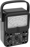 |
The analog display shows the magnitude and rate of change more easily than digital multimeters when measuring rapidly changing electrical values. Simpson multimeters are known for their ruggedness and reliability.
Average-Sensing AC Calculation—Average-sensing multimeters take accurate AC measurements when testing equipment that has a linear load and draws current in a smooth sine wave, such as standard induction motors.
Multimeters | Test Leads | ||||||||||||||||||||||||||||||||||||||||||||||||||||||||||||||||||||||||||||||||||||||||||||||||||
|---|---|---|---|---|---|---|---|---|---|---|---|---|---|---|---|---|---|---|---|---|---|---|---|---|---|---|---|---|---|---|---|---|---|---|---|---|---|---|---|---|---|---|---|---|---|---|---|---|---|---|---|---|---|---|---|---|---|---|---|---|---|---|---|---|---|---|---|---|---|---|---|---|---|---|---|---|---|---|---|---|---|---|---|---|---|---|---|---|---|---|---|---|---|---|---|---|---|---|---|
Measures | Diag. Screen Size | Color | Max. AC Voltage, V AC | Max. DC Voltage, V DC | DC Voltage Accuracy | Max. AC Current, amp | Max. DC Current, amp | Hardware Features | Software Features | Includes | Each | Pair | |||||||||||||||||||||||||||||||||||||||||||||||||||||||||||||||||||||||||||||||||||||||
Average-Sensing AC Calculation | |||||||||||||||||||||||||||||||||||||||||||||||||||||||||||||||||||||||||||||||||||||||||||||||||||
Multimeters | |||||||||||||||||||||||||||||||||||||||||||||||||||||||||||||||||||||||||||||||||||||||||||||||||||
| AC Voltage, DC Current, DC Voltage, Resistance | 4.8" | Black | 1,000 | 1,000 | 2% | — | 10 | — | — | Alligator Clips, Test Leads | 7250K11 | 0000000 | 7250K21 | 000000 | |||||||||||||||||||||||||||||||||||||||||||||||||||||||||||||||||||||||||||||||||||||
| AC Voltage, DC Current, DC Voltage, Resistance | 4.8" | Black | 1,000 | 1,000 | 2% | — | 10 | Overload Protection | Sound Alert for Continuity | Alligator Clips, Test Leads | 7250K15 | 000000 | 7250K21 | 00000 | |||||||||||||||||||||||||||||||||||||||||||||||||||||||||||||||||||||||||||||||||||||
| AC Voltage, DC Current, DC Voltage, Resistance | 5.2" | Yellow | 1,000 | 1,000 | 2% | — | 10 | — | Sound Alert for Continuity | Alligator Clips, Test Leads | 7250K13 | 000000 | 7250K25 | 00000 | |||||||||||||||||||||||||||||||||||||||||||||||||||||||||||||||||||||||||||||||||||||
| AC Voltage, DC Current, DC Voltage, Resistance | 5.2" | Yellow | 1,000 | 1,000 | 2% | — | 10 | Overload Protection | Sound Alert for Continuity | Alligator Clips, Test Leads | 7250K16 | 000000 | 7250K25 | 00000 | |||||||||||||||||||||||||||||||||||||||||||||||||||||||||||||||||||||||||||||||||||||
CAT III, 600V Safety Rating | |||||||||||||||||||||||||||||||||||||||||||||||||||||||||||||||||||||||||||||||||||||||||||||||||||
| AC Current, AC Voltage, DC Current, DC Voltage, Resistance | 5.3" | Black | 600 | 600 | 2% | 10 | 10 | Overload Protection | — | Alligator Clips, Carrying Case, Test Leads | 7250K14 | 000000 | 7250K22 | 00000 | |||||||||||||||||||||||||||||||||||||||||||||||||||||||||||||||||||||||||||||||||||||
Analog Multimeters
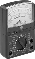 |
Measure rapidly changing electrical values with an analog display that shows the magnitude and rate of change more easily than digital multimeters.
Average-Sensing AC Calculation—Average-sensing multimeters take accurate AC measurements when testing equipment that has a linear load and draws current in a smooth sine wave, such as standard induction motors.
Batteries | |||||||||||||||||||||||||||||||||||||||||||||||||||||||||||||||||||||||||||||||||||||||||||||||||||
|---|---|---|---|---|---|---|---|---|---|---|---|---|---|---|---|---|---|---|---|---|---|---|---|---|---|---|---|---|---|---|---|---|---|---|---|---|---|---|---|---|---|---|---|---|---|---|---|---|---|---|---|---|---|---|---|---|---|---|---|---|---|---|---|---|---|---|---|---|---|---|---|---|---|---|---|---|---|---|---|---|---|---|---|---|---|---|---|---|---|---|---|---|---|---|---|---|---|---|---|
Measures | Diag. Screen Size | Max. AC Voltage, V AC | Max. DC Voltage, V DC | DC Voltage Accuracy | Max. DC Current, amp | Hardware Features | Includes | Size | No. Req. | Each | |||||||||||||||||||||||||||||||||||||||||||||||||||||||||||||||||||||||||||||||||||||||||
Average-Sensing AC Calculation | |||||||||||||||||||||||||||||||||||||||||||||||||||||||||||||||||||||||||||||||||||||||||||||||||||
CAT II, 1,000V Safety Rating | |||||||||||||||||||||||||||||||||||||||||||||||||||||||||||||||||||||||||||||||||||||||||||||||||||
| AC Voltage, DC Current, DC Voltage, Resistance | 4.3" | 1,000 | 1,000 | 4% | 10 | Overload Protection | Test Leads | AAA | 2 | 7097K33 | 000000 | ||||||||||||||||||||||||||||||||||||||||||||||||||||||||||||||||||||||||||||||||||||||||
Analog Clamp-on-Jaw Multimeters
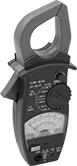 |
Measure rapidly changing electrical values more easily than with digital multimeters. Convenient for taking frequent high current measurements, the meters have jaws that surround a cable to test current without interrupting the circuit. Use the included test leads to perform other electrical tests.
Average-Sensing AC Calculation—Average-sensing multimeters take accurate AC measurements when testing equipment that has a linear load and draws current in a smooth sine wave, such as standard induction motors.
Batteries | |||||||||||||||||||||||||||||||||||||||||||||||||||||||||||||||||||||||||||||||||||||||||||||||||||
|---|---|---|---|---|---|---|---|---|---|---|---|---|---|---|---|---|---|---|---|---|---|---|---|---|---|---|---|---|---|---|---|---|---|---|---|---|---|---|---|---|---|---|---|---|---|---|---|---|---|---|---|---|---|---|---|---|---|---|---|---|---|---|---|---|---|---|---|---|---|---|---|---|---|---|---|---|---|---|---|---|---|---|---|---|---|---|---|---|---|---|---|---|---|---|---|---|---|---|---|
Jaw Opening | Measures | Max. AC Voltage, V AC | Max. DC Voltage, V DC | DC Voltage Accuracy | Max. AC Current, amp | Hardware Features | Includes | Size | Req. | Each | |||||||||||||||||||||||||||||||||||||||||||||||||||||||||||||||||||||||||||||||||||||||||
Average-Sensing AC Calculation | |||||||||||||||||||||||||||||||||||||||||||||||||||||||||||||||||||||||||||||||||||||||||||||||||||
| 1.5" | AC Current, AC Voltage, DC Voltage, Resistance | 600 | 60 | 4% | 600 | Overload Protection | Test Leads | AA | Yes | 7615K57 | 0000000 | ||||||||||||||||||||||||||||||||||||||||||||||||||||||||||||||||||||||||||||||||||||||||
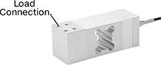
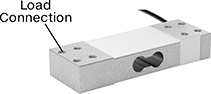
Configurable Tension and Compression Force Sensors
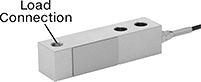
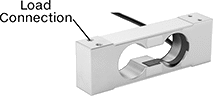
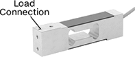
Rectangle
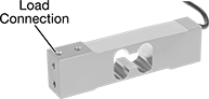 | 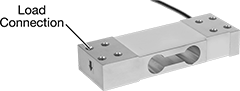 | 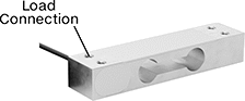 |
With 4 Threaded Holes | With 8 Threaded Through Holes | With 4 Threaded Through Holes |
Wt. Cap. | Accuracy | Wt. Measuring Increments | Thread Size | Lg. | Wd. | Ht. | Sensor Material | Temp. Range, ° F | Enclosure Rating | Each | |||||||||||||||||||||||||||||||||||||||||||||||||||||||||||||||||||||||||||||||||||||||||
|---|---|---|---|---|---|---|---|---|---|---|---|---|---|---|---|---|---|---|---|---|---|---|---|---|---|---|---|---|---|---|---|---|---|---|---|---|---|---|---|---|---|---|---|---|---|---|---|---|---|---|---|---|---|---|---|---|---|---|---|---|---|---|---|---|---|---|---|---|---|---|---|---|---|---|---|---|---|---|---|---|---|---|---|---|---|---|---|---|---|---|---|---|---|---|---|---|---|---|---|
Measures Tension and Compression | |||||||||||||||||||||||||||||||||||||||||||||||||||||||||||||||||||||||||||||||||||||||||||||||||||
With 4 Threaded Through Holes | |||||||||||||||||||||||||||||||||||||||||||||||||||||||||||||||||||||||||||||||||||||||||||||||||||
| 10.5 oz., 300 g | ±0.0021 oz., ±0.06 g | 0.001 oz., 0.01 g | M3 × 0.5 mm | 2 13/16" | 1/2" | 3/4" | Aluminum | 15 to 100 | IP66 | 3487N356 | 0000000 | ||||||||||||||||||||||||||||||||||||||||||||||||||||||||||||||||||||||||||||||||||||||||
| 2.2 lb., 1 kg | ±0.007 oz., ±0.2 g | 0.001 oz., 0.1 g | M3 × 0.5 mm | 2 13/16" | 1/2" | 3/4" | Aluminum | 15 to 100 | IP66 | 3487N357 | 000000 | ||||||||||||||||||||||||||||||||||||||||||||||||||||||||||||||||||||||||||||||||||||||||
| 4.4 lb., 2 kg | ±0.014 oz., ±0.4 g | 0.001 oz., 0.1 g | M3 × 0.5 mm | 2 13/16" | 1/2" | 3/4" | Aluminum | 15 to 100 | IP66 | 3487N358 | 000000 | ||||||||||||||||||||||||||||||||||||||||||||||||||||||||||||||||||||||||||||||||||||||||
| 6.6 lb., 3 kg | ±0.016 oz., ±0.5 g | 0.001 oz., 0.1 g | M6 × 1 mm | 5 1/8" | 1 3/16" | 7/8" | Aluminum | 15 to 100 | IP65 | 3487N511 | 000000 | ||||||||||||||||||||||||||||||||||||||||||||||||||||||||||||||||||||||||||||||||||||||||
| 6.6 lb., 3 kg | ±0.021 oz., ±0.6 g | 0.01 oz., 0.1 g | M3 × 0.5 mm | 2 13/16" | 1/2" | 3/4" | Aluminum | 15 to 100 | IP66 | 3487N359 | 000000 | ||||||||||||||||||||||||||||||||||||||||||||||||||||||||||||||||||||||||||||||||||||||||
| 11 lb., 5 kg | ±0.026 oz., ±0.8 g | 0.01 oz., 0.1 g | M6 × 1 mm | 5 1/8" | 1 3/16" | 7/8" | Aluminum | 15 to 100 | IP65 | 3487N512 | 000000 | ||||||||||||||||||||||||||||||||||||||||||||||||||||||||||||||||||||||||||||||||||||||||
| 22 lb., 10 kg | ±0.053 oz., ±1.5 g | 0.01 oz., 0.1 g | M6 × 1 mm | 5 1/8" | 1 3/16" | 7/8" | Aluminum | 15 to 100 | IP65 | 3487N513 | 000000 | ||||||||||||||||||||||||||||||||||||||||||||||||||||||||||||||||||||||||||||||||||||||||
| 44 lb., 20 kg | ±0.11 oz., ±3 g | 0.01 oz., 0.001 kg | M6 × 1 mm | 5 1/8" | 1 3/16" | 7/8" | Aluminum | 15 to 100 | IP65 | 3487N514 | 000000 | ||||||||||||||||||||||||||||||||||||||||||||||||||||||||||||||||||||||||||||||||||||||||
With 8 Threaded Through Holes | |||||||||||||||||||||||||||||||||||||||||||||||||||||||||||||||||||||||||||||||||||||||||||||||||||
| 110 lb., 50 kg | ±0.35 oz., ±10 g | 0.01 lb., 0.01 kg | M8 × 1.25 mm | 6 7/8" | 2 3/8" | 1 3/16" | Alloy Steel | 15 to 100 | — | 3487N39 | 000000 | ||||||||||||||||||||||||||||||||||||||||||||||||||||||||||||||||||||||||||||||||||||||||
Measures Tension and Compression Legal-for-Trade | |||||||||||||||||||||||||||||||||||||||||||||||||||||||||||||||||||||||||||||||||||||||||||||||||||
With 4 Threaded Holes | |||||||||||||||||||||||||||||||||||||||||||||||||||||||||||||||||||||||||||||||||||||||||||||||||||
| 22 lb., 10 kg | ±0.07 oz., ±2 g | 0.01 lb., 0.001 kg | 1/4"-20 | 5 15/16" | 1" | 1 9/16" | Aluminum | 15 to 100 | IP67 | 3487N418 | 000000 | ||||||||||||||||||||||||||||||||||||||||||||||||||||||||||||||||||||||||||||||||||||||||
| 44 lb., 20 kg | ±0.14 oz., ±4 g | 0.01 lb., 0.001 kg | 1/4"-20 | 5 15/16" | 1" | 1 9/16" | Aluminum | 15 to 100 | IP67 | 3487N419 | 000000 | ||||||||||||||||||||||||||||||||||||||||||||||||||||||||||||||||||||||||||||||||||||||||
| 110 lb., 50 kg | ±0.35 oz., ±10 g | 0.01 lb., 0.01 kg | 1/4"-20 | 5 15/16" | 1" | 1 9/16" | Aluminum | 15 to 100 | IP67 | 3487N42 | 000000 | ||||||||||||||||||||||||||||||||||||||||||||||||||||||||||||||||||||||||||||||||||||||||
| 220 lb., 100 kg | ±0.7 oz., ±20 g | 0.01 oz., 0.001 g | 1/4"-20 | 5 15/16" | 1" | 1 9/16" | Aluminum | 15 to 100 | IP67 | 3487N421 | 000000 | ||||||||||||||||||||||||||||||||||||||||||||||||||||||||||||||||||||||||||||||||||||||||
 |
Connection hubs combine the measurements of multiple tension and compression force sensors together.
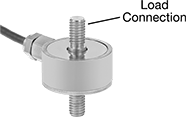
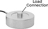
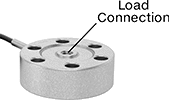
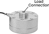
Round
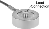 | 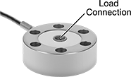 |
Button | Threaded Through Hole |
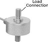
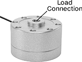 | 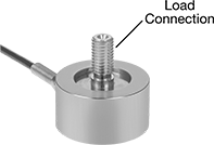 |
Threaded Standoff | Threaded Stud |
 | |
Dual-Sided Threaded Stud |
Round sensors have a low profile to fit in tight-clearance spaces.
Threaded Stud—Those with a threaded stud screw into equipment.
Threaded Through Hole—Those with a threaded through hole are also known as pancake load cells. They can be bolted to surfaces in any orientation and are commonly used to measure clamping forces. They can be mounted in any orientation.
Button—Those with a button are often used to measure weight in packaging machinery and for pressure sensing in medical device prototypes. Those without mounting holes are about as thin as a credit card. To mount, sandwich them between two plates or use a thin layer of adhesive. They can only be used for compression applications.
Dual-Sided Threaded Stud—Those with a dual-sided threaded stud can monitor push-pull forces. For example, they might be used to test the durability of products that repeatedly fold and unfold.
Threaded Standoff—Those with a threaded standoff have a threaded hole to connect to eye bolts, rod ends, and threaded rods. They’re commonly mounted upside-down between a tank and a leveling mount to weigh material in small tanks and silos.
IP66 Enclosure Rating—IP66 sensors stand up to spraying water.
Enclosure Rating—IP-rated sensors seal out dust.
Load Connection | Mounting Holes | ||||||||||||||||||||||||||||||||||||||||||||||||||||||||||||||||||||||||||||||||||||||||||||||||||
|---|---|---|---|---|---|---|---|---|---|---|---|---|---|---|---|---|---|---|---|---|---|---|---|---|---|---|---|---|---|---|---|---|---|---|---|---|---|---|---|---|---|---|---|---|---|---|---|---|---|---|---|---|---|---|---|---|---|---|---|---|---|---|---|---|---|---|---|---|---|---|---|---|---|---|---|---|---|---|---|---|---|---|---|---|---|---|---|---|---|---|---|---|---|---|---|---|---|---|---|
Wt. Cap. | Accuracy | Wt. Measuring Increments | Thread Size | Stud Lg. | Dia. | Ht. | Sensor Material | Temp. Range, ° F | Location | Fasteners Included | No. of | Diameter, mm | Thread Size | Enclosure Rating | Each | ||||||||||||||||||||||||||||||||||||||||||||||||||||||||||||||||||||||||||||||||||||
Measures Tension and Compression | |||||||||||||||||||||||||||||||||||||||||||||||||||||||||||||||||||||||||||||||||||||||||||||||||||
With 1 Threaded Stud | |||||||||||||||||||||||||||||||||||||||||||||||||||||||||||||||||||||||||||||||||||||||||||||||||||
| 110 lb.; 50 kg | ±8.8 oz., ±250 g | 0.01 lb., 0.001 kg | M12 × 1.75 mm | 1" | 2" | 2" | Alloy Steel | 0 to 140 | Bottom | No | 4 | — | M5 × 0.8 mm | IP66 | 3487N194 | 0000000 | |||||||||||||||||||||||||||||||||||||||||||||||||||||||||||||||||||||||||||||||||||
| 220 lb.; 100 kg | ±1.1 lb., ±500 g | 0.01 lb., 0.01 kg | M12 × 1.75 mm | 1" | 2" | 2" | Alloy Steel | 0 to 140 | Bottom | No | 4 | — | M5 × 0.8 mm | IP66 | 3487N195 | 000000 | |||||||||||||||||||||||||||||||||||||||||||||||||||||||||||||||||||||||||||||||||||
| 440 lb.; 200 kg | ±2.2 lb., ±1 kg | 0.01 lb., 0.01 kg | M12 × 1.75 mm | 1" | 2" | 2" | Alloy Steel | 0 to 140 | Bottom | No | 4 | — | M5 × 0.8 mm | IP66 | 3487N196 | 000000 | |||||||||||||||||||||||||||||||||||||||||||||||||||||||||||||||||||||||||||||||||||
With 1 Threaded Through Hole | |||||||||||||||||||||||||||||||||||||||||||||||||||||||||||||||||||||||||||||||||||||||||||||||||||
| 1,100 lb.; 500 kg | ±8.8 oz., ±250 g | 0.1 lb., 0.01 kg | M10 × 1.5 mm | — | 2 15/16" | 1" | Alloy Steel | 0 to 140 | Top | No | 6 | 6.5 | — | — | 3487N223 | 000000 | |||||||||||||||||||||||||||||||||||||||||||||||||||||||||||||||||||||||||||||||||||
| 2,200 lb.; 1,000 kg | ±1.1 lb., ±500 g | 0.1 lb., 0.01 kg | M12 × 1.75 mm | — | 3 9/16" | 1" | Alloy Steel | 0 to 140 | Top | No | 6 | 8.5 | — | — | 3487N224 | 000000 | |||||||||||||||||||||||||||||||||||||||||||||||||||||||||||||||||||||||||||||||||||
| 5,510 lb.; 2,500 kg | ±2.8 lb., ±1.25 kg | 0.1 lb., 0.1 kg | M12 × 1.75 mm | — | 3 9/16" | 1" | Alloy Steel | 0 to 140 | Top | No | 6 | 8.5 | — | — | 3487N225 | 000000 | |||||||||||||||||||||||||||||||||||||||||||||||||||||||||||||||||||||||||||||||||||
| 11,020 lb.; 5,000 kg | ±5.5 lb., ±2.5 kg | 1 lb., 0.1 kg | M24 × 3 mm | — | 5 1/2" | 1 3/4" | Alloy Steel | 0 to 140 | Top | No | 8 | 11 | — | — | 3487N226 | 000000 | |||||||||||||||||||||||||||||||||||||||||||||||||||||||||||||||||||||||||||||||||||
With 2 Dual-Sided Threaded Studs | |||||||||||||||||||||||||||||||||||||||||||||||||||||||||||||||||||||||||||||||||||||||||||||||||||
| 2.2 lb.; 1 kg | ±0.35 oz., ±10 g | 0.001 oz., 0.1 g | M3 × 0.5 mm | 5/16" | 1" | 1 1/4" | Alloy Steel | 0 to 140 | — | — | — | — | — | — | 3487N452 | 000000 | |||||||||||||||||||||||||||||||||||||||||||||||||||||||||||||||||||||||||||||||||||
| 4.4 lb.; 2 kg | ±0.7 oz., ±20 g | 0.001 oz., 0.1 g | M3 × 0.5 mm | 5/16" | 1" | 1 1/4" | Alloy Steel | 0 to 140 | — | — | — | — | — | — | 3487N453 | 000000 | |||||||||||||||||||||||||||||||||||||||||||||||||||||||||||||||||||||||||||||||||||
| 11 lb.; 5 kg | ±1.8 oz., ±50 g | 0.01 oz., 0.1 g | M5 × 0.8 mm | 5/16" | 1" | 1 7/16" | Alloy Steel | 0 to 140 | — | — | — | — | — | — | 3487N454 | 000000 | |||||||||||||||||||||||||||||||||||||||||||||||||||||||||||||||||||||||||||||||||||
| 22 lb.; 10 kg | ±0.35 oz., ±100 g | 0.01 lb., 0.001 kg | M5 × 0.8 mm | 5/16" | 1" | 1 7/16" | Alloy Steel | 0 to 140 | — | — | — | — | — | — | 3487N455 | 000000 | |||||||||||||||||||||||||||||||||||||||||||||||||||||||||||||||||||||||||||||||||||
| 220 lb.; 100 kg | ±2.2 lb., ±1 kg | 0.01 lb., 0.001 kg | M6 × 1 mm | 5/16" | 1" | 1 7/16" | Alloy Steel | 0 to 140 | — | — | — | — | — | — | 3487N456 | 000000 | |||||||||||||||||||||||||||||||||||||||||||||||||||||||||||||||||||||||||||||||||||
With 2 Threaded Standoffs | |||||||||||||||||||||||||||||||||||||||||||||||||||||||||||||||||||||||||||||||||||||||||||||||||||
| 25,000 lb.; 11,335 kg | ±12.5 lb., ±5.7 kg | 1 lb., 1 kg | 3/4"-16 | — | 4 3/4" | 3 1/16" | Alloy Steel | -40 to 175 | — | — | — | — | — | — | 3487N519 | 000000 | |||||||||||||||||||||||||||||||||||||||||||||||||||||||||||||||||||||||||||||||||||
Measures Compression Not Legal-for-Trade | |||||||||||||||||||||||||||||||||||||||||||||||||||||||||||||||||||||||||||||||||||||||||||||||||||
With 1 Button | |||||||||||||||||||||||||||||||||||||||||||||||||||||||||||||||||||||||||||||||||||||||||||||||||||
| 4.4 lb.; 2 kg | ±0.7 oz., ±20 g | 0.1 lb., 0.01 kg | — | — | 1/2" | 1/4" | Alloy Steel | 0 to 140 | — | — | — | — | — | — | 3487N446 | 000000 | |||||||||||||||||||||||||||||||||||||||||||||||||||||||||||||||||||||||||||||||||||
| 22 lb.; 10 kg | ±3.5 oz., ±100 g | 0.1 lb., 0.1 kg | — | — | 1/2" | 1/4" | Alloy Steel | 0 to 140 | — | — | — | — | — | — | 3487N447 | 000000 | |||||||||||||||||||||||||||||||||||||||||||||||||||||||||||||||||||||||||||||||||||
| 55 lb.; 25 kg | ±0.44 oz., ±12.5 g | 0.01 lb., 0.01 kg | — | — | 2 1/16" | 7/8" | Alloy Steel | 0 to 140 | Bottom | No | 4 | — | M5 × 0.8 mm | IP66 | 3487N176 | 000000 | |||||||||||||||||||||||||||||||||||||||||||||||||||||||||||||||||||||||||||||||||||
| 110 lb.; 50 kg | ±0.88 oz., ±25 g | 0.01 lb., 0.001 kg | — | — | 2 1/16" | 7/8" | Alloy Steel | 0 to 140 | Bottom | No | 4 | — | M5 × 0.8 mm | IP66 | 3487N177 | 000000 | |||||||||||||||||||||||||||||||||||||||||||||||||||||||||||||||||||||||||||||||||||
| 220 lb.; 100 kg | ±1.8 oz., ±50 g | 0.01 lb., 0.01 kg | — | — | 2 1/16" | 7/8" | Alloy Steel | 0 to 140 | Bottom | No | 4 | — | M5 × 0.8 mm | IP66 | 3487N178 | 000000 | |||||||||||||||||||||||||||||||||||||||||||||||||||||||||||||||||||||||||||||||||||
| 550 lb.; 250 kg | ±4.4 oz., ±125 g | 0.01 lb., 0.01 kg | — | — | 2 1/16" | 7/8" | Alloy Steel | 0 to 140 | Bottom | No | 4 | — | M5 × 0.8 mm | IP66 | 3487N179 | 000000 | |||||||||||||||||||||||||||||||||||||||||||||||||||||||||||||||||||||||||||||||||||
| 1,100 lb.; 500 kg | ±8.8 oz., ±250 g | 0.1 lb., 0.01 kg | — | — | 2 1/16" | 7/8" | Alloy Steel | 0 to 140 | Bottom | No | 4 | — | M5 × 0.8 mm | IP66 | 3487N18 | 000000 | |||||||||||||||||||||||||||||||||||||||||||||||||||||||||||||||||||||||||||||||||||
| 2,200 lb.; 1,000 kg | ±1.1 lb., ±500 g | 0.1 lb., 0.01 kg | — | — | 2 1/16" | 7/8" | Alloy Steel | 0 to 140 | Bottom | No | 4 | — | M5 × 0.8 mm | IP66 | 3487N181 | 000000 | |||||||||||||||||||||||||||||||||||||||||||||||||||||||||||||||||||||||||||||||||||
| 4,405 lb.; 2,000 kg | ±2.2 lb., ±1 kg | 0.1 lb., 0.1 kg | — | — | 3 1/4" | 1 3/4" | Alloy Steel | 0 to 140 | Bottom | No | 3 | — | M8 × 1.25 mm | IP66 | 3487N517 | 000000 | |||||||||||||||||||||||||||||||||||||||||||||||||||||||||||||||||||||||||||||||||||
| 11,020 lb.; 5,000 kg | ±5.5 lb., ±2.5 kg | 1 lb., 0.1 kg | — | — | 3 1/4" | 1 3/4" | Alloy Steel | 0 to 140 | Bottom | No | 3 | — | M8 × 1.25 mm | IP66 | 3487N518 | 000000 | |||||||||||||||||||||||||||||||||||||||||||||||||||||||||||||||||||||||||||||||||||
|
Connection hubs combine the measurements of multiple tension and compression force sensors together.
S-Shape
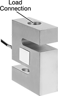 |
Threaded Through Hole |
S-shaped sensors are a common choice for monitoring and testing tension in wires, cords, ropes, and harnesses. They are often used in hanging scales. Also known as S-beam load cells.
IP67 Enclosure Rating—IP67 sensors won’t fail if briefly submerged.
Enclosure Rating—IP-rated sensors seal out dust.
Wt. Cap. | Accuracy | Wt. Measuring Increments | Thread Size | Lg. | Wd. | Ht. | Sensor Material | Temp. Range, ° F | Enclosure Rating | Each | |||||||||||||||||||||||||||||||||||||||||||||||||||||||||||||||||||||||||||||||||||||||||
|---|---|---|---|---|---|---|---|---|---|---|---|---|---|---|---|---|---|---|---|---|---|---|---|---|---|---|---|---|---|---|---|---|---|---|---|---|---|---|---|---|---|---|---|---|---|---|---|---|---|---|---|---|---|---|---|---|---|---|---|---|---|---|---|---|---|---|---|---|---|---|---|---|---|---|---|---|---|---|---|---|---|---|---|---|---|---|---|---|---|---|---|---|---|---|---|---|---|---|---|
Measures Tension and Compression | |||||||||||||||||||||||||||||||||||||||||||||||||||||||||||||||||||||||||||||||||||||||||||||||||||
With 2 Threaded Through Holes | |||||||||||||||||||||||||||||||||||||||||||||||||||||||||||||||||||||||||||||||||||||||||||||||||||
| 11 lb.; 5 kg | ±0.88 oz., ±25 g | 0.01 lb., 0.001 kg | M3 × 0.5 mm | 11/16" | 1/4" | 3/4" | Alloy Steel | 0 to 140 | — | 3487N334 | 0000000 | ||||||||||||||||||||||||||||||||||||||||||||||||||||||||||||||||||||||||||||||||||||||||
| 25 lb.; 11 kg | ±0.08 oz., ±2.2 g | 0.01 lb., 0.001 kg | 1/4"-28 | 2" | 1/2" | 2 1/2" | Alloy Steel | 0 to 140 | — | 3487N257 | 000000 | ||||||||||||||||||||||||||||||||||||||||||||||||||||||||||||||||||||||||||||||||||||||||
| 50 lb.; 22 kg | ±0.16 oz., ±4.4 g | 0.01 lb., 0.001 kg | 1/4"-28 | 2" | 1/2" | 2 1/2" | Alloy Steel | 0 to 140 | — | 3487N258 | 000000 | ||||||||||||||||||||||||||||||||||||||||||||||||||||||||||||||||||||||||||||||||||||||||
| 100 lb.; 45 kg | ±0.32 oz., ±9 g | 0.01 lb., 0.01 kg | 1/4"-28 | 2" | 1/2" | 2 1/2" | Alloy Steel | 0 to 140 | — | 3487N259 | 000000 | ||||||||||||||||||||||||||||||||||||||||||||||||||||||||||||||||||||||||||||||||||||||||
| 110 lb.; 50 kg | ±8.8 oz., ±250 g | 0.1 lb., 0.001 kg | M4 × 0.7 mm | 11/16" | 1/4" | 3/4" | Alloy Steel | 0 to 140 | — | 3487N336 | 000000 | ||||||||||||||||||||||||||||||||||||||||||||||||||||||||||||||||||||||||||||||||||||||||
| 250 lb.; 113 kg | ±0.8 oz., ±22.6 g | 0.01 lb., 0.001 kg | 1/2"-20 | 2" | 3/4" | 3" | Alloy Steel | 0 to 140 | — | 3487N26 | 000000 | ||||||||||||||||||||||||||||||||||||||||||||||||||||||||||||||||||||||||||||||||||||||||
| 500 lb.; 225 kg | ±1.6 oz., ±45 g | 0.1 lb., 0.01 kg | 1/2"-20 | 2" | 3/4" | 3" | Alloy Steel | 0 to 140 | — | 3487N261 | 000000 | ||||||||||||||||||||||||||||||||||||||||||||||||||||||||||||||||||||||||||||||||||||||||
| 1,000 lb.; 450 kg | ±3.2 oz., ±90 g | 0.01 lb., 0.01 kg | 1/2"-20 | 2" | 3/4" | 3" | Alloy Steel | 0 to 140 | — | 3487N262 | 000000 | ||||||||||||||||||||||||||||||||||||||||||||||||||||||||||||||||||||||||||||||||||||||||
| 2,500 lb.; 1,130 kg | ±8 oz., ±226 g | 0.1 lb., 0.1 kg | 1/2"-20 | 2" | 1" | 3" | Alloy Steel | 0 to 140 | — | 3487N263 | 000000 | ||||||||||||||||||||||||||||||||||||||||||||||||||||||||||||||||||||||||||||||||||||||||
| 5,000 lb.; 2,265 kg | ±1 lb., ±453 g | 0.1 lb., 0.1 kg | 3/4"-16 | 3" | 1" | 4 1/4" | Alloy Steel | 0 to 140 | — | 3487N264 | 000000 | ||||||||||||||||||||||||||||||||||||||||||||||||||||||||||||||||||||||||||||||||||||||||
| 10,000 lb.; 4,535 kg | ±2 lb., ±907 g | 0.1 lb., 0.1 kg | 3/4"-16 | 3" | 1" | 4 1/4" | Alloy Steel | 0 to 140 | — | 3487N265 | 000000 | ||||||||||||||||||||||||||||||||||||||||||||||||||||||||||||||||||||||||||||||||||||||||
| 20,000 lb.; 9,070 kg | ±4 lb., ±1.8 kg | 1 lb., 0.1 kg | 1 1/4"-12 | 5" | 2" | 7" | Alloy Steel | 0 to 140 | — | 3487N266 | 000000 | ||||||||||||||||||||||||||||||||||||||||||||||||||||||||||||||||||||||||||||||||||||||||
| 40,000 lb.; 18,140 kg | ±8 lb., ±3.6 kg | 1 lb., 1 kg | 1 1/2"-12 | 5 1/2" | 2 3/8" | 7 3/8" | Alloy Steel | 0 to 140 | — | 3487N267 | 00000000 | ||||||||||||||||||||||||||||||||||||||||||||||||||||||||||||||||||||||||||||||||||||||||
Measures Tension and Compression Legal-for-Trade | |||||||||||||||||||||||||||||||||||||||||||||||||||||||||||||||||||||||||||||||||||||||||||||||||||
With 2 Threaded Through Holes | |||||||||||||||||||||||||||||||||||||||||||||||||||||||||||||||||||||||||||||||||||||||||||||||||||
| 25 lb.; 11 kg | ±0.12 oz., ±3.4 g | 0.01 lb., 0.01 kg | 1/4"-28 | 2" | 1/2" | 2 1/2" | Alloy Steel | -40 to 175 | IP67 | 3487N515 | 000000 | ||||||||||||||||||||||||||||||||||||||||||||||||||||||||||||||||||||||||||||||||||||||||
| 50 lb.; 22 kg | ±0.24 oz., ±6.8 g | 0.01 lb., 0.01 kg | 1/4"-28 | 2" | 1/2" | 2 1/2" | Alloy Steel | -40 to 175 | IP67 | 3487N516 | 000000 | ||||||||||||||||||||||||||||||||||||||||||||||||||||||||||||||||||||||||||||||||||||||||
|
Connection hubs combine the measurements of multiple tension and compression force sensors together.
Ready-to-Use Tension and Compression Force Sensor Kits
Rectangle
 |
PLC Connection Kit |
|
With 4 Threaded Holes |
|
With 4 Threaded Through Holes |
|
With 8 Threaded Through Holes |
Rectangle sensors are also known as single-point or shear beam load cells. They can be used in multiples across surfaces to measure uneven loads. They’re often used in bench-top and floor scales where loads are often unbalanced. They’re also used in packaging, machine bins, conveyors, and chutes.
IP66 Enclosure Rating— IP66 rated sensors stand up to spraying water.
IP67 Enclosure Rating—IP67 rated sensors won’t fail if briefly submerged.
Threaded Through Hole—Sensors with a threaded through hole are also known as pancake load cells. They can be bolted to surfaces in any orientation and are commonly used to measure clamping forces
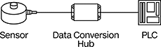
PLC Connection Kits—PLC connection kits send an analog signal to your PLC to trigger actions such as diverting items that exceed a certain weight on a conveyor. They include a calibrated sensor and a data conversion hub. They’re not for use with LCD displays.
Enclosure Rating—IP rated sensors seal out dust.
PLC Connection Kits | |||||||||||||||||||||||||||||||||||||||||||||||||||||||||||||||||||||||||||||||||||||||||||||||||||
|---|---|---|---|---|---|---|---|---|---|---|---|---|---|---|---|---|---|---|---|---|---|---|---|---|---|---|---|---|---|---|---|---|---|---|---|---|---|---|---|---|---|---|---|---|---|---|---|---|---|---|---|---|---|---|---|---|---|---|---|---|---|---|---|---|---|---|---|---|---|---|---|---|---|---|---|---|---|---|---|---|---|---|---|---|---|---|---|---|---|---|---|---|---|---|---|---|---|---|---|
Wt. Cap. | Accuracy | Wt. Measuring Increments | Thread Size | Lg. | Wd. | Ht. | Sensor Material | Temp. Range, ° F | Each | ||||||||||||||||||||||||||||||||||||||||||||||||||||||||||||||||||||||||||||||||||||||||||
Measures Compression and Tension (Not Legal-for-Trade) | |||||||||||||||||||||||||||||||||||||||||||||||||||||||||||||||||||||||||||||||||||||||||||||||||||
With 8 Threaded Through Holes | |||||||||||||||||||||||||||||||||||||||||||||||||||||||||||||||||||||||||||||||||||||||||||||||||||
| 110 lb., 50 kg | ±0.35 oz., ±10 g | 0.01 lb., 0.01 kg | M8 × 1.25 mm | 6 7/8" | 2 3/8" | 1 3/16" | Alloy Steel | 15 to 100 | 3487N414 | 000000000 | |||||||||||||||||||||||||||||||||||||||||||||||||||||||||||||||||||||||||||||||||||||||||
Measures Compression, and Tension—IP66 Rated (Not Legal-for-Trade) | |||||||||||||||||||||||||||||||||||||||||||||||||||||||||||||||||||||||||||||||||||||||||||||||||||
With 4 Threaded Through Holes | |||||||||||||||||||||||||||||||||||||||||||||||||||||||||||||||||||||||||||||||||||||||||||||||||||
| 10.5 oz., 300 g | ±0.0021 oz., ±0.06 g | 0.001 oz., 0.01 g | M3 × 0.5 mm | 2 13/16" | 1/2" | 3/4" | Aluminum | 15 to 100 | 3487N386 | 000000 | |||||||||||||||||||||||||||||||||||||||||||||||||||||||||||||||||||||||||||||||||||||||||
| 2.2 lb., 1 kg | ±0.007 oz., ±0.2 g | 0.001 oz., 0.1 g | M3 × 0.5 mm | 2 13/16" | 1/2" | 3/4" | Aluminum | 15 to 100 | 3487N387 | 000000 | |||||||||||||||||||||||||||||||||||||||||||||||||||||||||||||||||||||||||||||||||||||||||
| 4.4 lb., 2 kg | ±0.014 oz., ±0.4 g | 0.001 oz., 0.1 g | M3 × 0.5 mm | 2 13/16" | 1/2" | 3/4" | Aluminum | 15 to 100 | 3487N388 | 000000 | |||||||||||||||||||||||||||||||||||||||||||||||||||||||||||||||||||||||||||||||||||||||||
| 6.6 lb., 3 kg | ±0.021 oz., ±0.6 g | 0.01 oz., 0.1 g | M3 × 0.5 mm | 2 13/16" | 1/2" | 3/4" | Aluminum | 15 to 100 | 3487N389 | 000000 | |||||||||||||||||||||||||||||||||||||||||||||||||||||||||||||||||||||||||||||||||||||||||
Measures Compression and Tension—IP67 Rated (Legal-for-Trade) | |||||||||||||||||||||||||||||||||||||||||||||||||||||||||||||||||||||||||||||||||||||||||||||||||||
With 4 Threaded Holes | |||||||||||||||||||||||||||||||||||||||||||||||||||||||||||||||||||||||||||||||||||||||||||||||||||
| 22 lb., 10 kg | ±0.07 oz., ±2 g | 0.01 lb., 1 kg | 1/4"-20 | 5 15/16" | 1" | 1 9/16" | Aluminum | 15 to 100 | 3487N442 | 000000 | |||||||||||||||||||||||||||||||||||||||||||||||||||||||||||||||||||||||||||||||||||||||||
| 44 lb., 20 kg | ±0.14 oz., ±4 g | 0.01 lb., 1 kg | 1/4"-20 | 5 15/16" | 1" | 1 9/16" | Aluminum | 15 to 100 | 3487N443 | 000000 | |||||||||||||||||||||||||||||||||||||||||||||||||||||||||||||||||||||||||||||||||||||||||
| 110 lb., 50 kg | ±0.35 oz., ±10 g | 0.01 lb., 0.01 kg | 1/4"-20 | 5 15/16" | 1" | 1 9/16" | Aluminum | 15 to 100 | 3487N444 | 000000 | |||||||||||||||||||||||||||||||||||||||||||||||||||||||||||||||||||||||||||||||||||||||||
| 220 lb., 100 kg | ±0.7 oz., ±20 g | 0.01 oz., 1 g | 1/4"-20 | 5 15/16" | 1" | 1 9/16" | Aluminum | 15 to 100 | 3487N445 | 000000 | |||||||||||||||||||||||||||||||||||||||||||||||||||||||||||||||||||||||||||||||||||||||||
Round
|
PLC Connection Kit |
| |
Button | Threaded Through Hole |
 | |
Dual-Sided Threaded Standoff | Threaded Stud |
| |
Dual-Sided Threaded Stud |
Round sensors have a low profile to fit in tight-clearance spaces.
Dual-Sided Threaded Stud—Those with a dual-sided threaded stud can monitor push-pull forces. For example, they might be used to test the durability of products that repeatedly fold and unfold.
Button—Those with a button are often used to measure weight in packaging machinery and for pressure sensing in medical device prototypes.
Threaded Stud—Those with a threaded stud screw into equipment.
Threaded Through Hole—Those with a threaded through hole are also known as pancake load cells. They can be bolted to surfaces in any orientation and are commonly used to measure clamping forces.
IP66 Enclosure Rating— IP66 rated sensors stand up to spraying water.
Threaded Stud—Sensors with a threaded stud screw into equipment.
Dual-Sided Threaded Stud—Sensors with a dual-sided threaded stud can monitor push-pull forces. For example, they might be used to test the durability of products that repeatedly fold and unfold.
PLC Connection Kits—PLC connection kits send an analog signal to your PLC to trigger actions such as diverting items that exceed a certain weight on a conveyor. They include a calibrated sensor and a data conversion hub. They’re not for use with LCD displays.
PLC/PC Connection Kits—PLC/PC connection kits combine the trigger functions of a PLC with the tracking and notification features of computer software. They include a calibrated force sensor, a data conversion hub, data-recording software, and a 6-ft. hub-to-USB cord.
Enclosure Rating—IP rated sensors seal out dust.
Load Connection | PLC Connection Kits | PLC/PC Connection Kits | |||||||||||||||||||||||||||||||||||||||||||||||||||||||||||||||||||||||||||||||||||||||||||||||||
|---|---|---|---|---|---|---|---|---|---|---|---|---|---|---|---|---|---|---|---|---|---|---|---|---|---|---|---|---|---|---|---|---|---|---|---|---|---|---|---|---|---|---|---|---|---|---|---|---|---|---|---|---|---|---|---|---|---|---|---|---|---|---|---|---|---|---|---|---|---|---|---|---|---|---|---|---|---|---|---|---|---|---|---|---|---|---|---|---|---|---|---|---|---|---|---|---|---|---|---|
Wt. Cap. | Accuracy | Wt. Measuring Increments | Thread Size | Stud Lg. | Dia. | Ht. | Sensor Material | Temp. Range, ° F | Each | Each | |||||||||||||||||||||||||||||||||||||||||||||||||||||||||||||||||||||||||||||||||||||||||
Measures Compression and Tension (Not Legal-for-Trade) | |||||||||||||||||||||||||||||||||||||||||||||||||||||||||||||||||||||||||||||||||||||||||||||||||||
With 1 Threaded Through Hole | |||||||||||||||||||||||||||||||||||||||||||||||||||||||||||||||||||||||||||||||||||||||||||||||||||
| 550 lb.; 250 kg | ±4.4 oz., ±125 g | 0.01 lb., 0.01 kg | M10 × 1.5 mm | — | 2 15/16" | 1" | Alloy Steel | 0 to 140 | 3487N252 | 000000000 | ——— | 0 | |||||||||||||||||||||||||||||||||||||||||||||||||||||||||||||||||||||||||||||||||||||||
| 1,100 lb.; 500 kg | ±8.8 oz., ±250 g | 0.1 lb., 0.01 kg | M10 × 1.5 mm | — | 2 15/16" | 1" | Alloy Steel | 0 to 140 | 3487N253 | 00000000 | ——— | 0 | |||||||||||||||||||||||||||||||||||||||||||||||||||||||||||||||||||||||||||||||||||||||
| 2,200 lb.; 1,000 kg | ±1.1 lb., ±500 g | 0.1 lb., 0.01 kg | M12 × 1.75 mm | — | 3 9/16" | 1" | Alloy Steel | 0 to 140 | 3487N254 | 00000000 | ——— | 0 | |||||||||||||||||||||||||||||||||||||||||||||||||||||||||||||||||||||||||||||||||||||||
| 5,510 lb.; 2,500 kg | ±2.8 lb., ±1.25 kg | 0.1 lb., 0.1 kg | M12 × 1.75 mm | — | 3 9/16" | 1" | Alloy Steel | 0 to 140 | 3487N255 | 00000000 | ——— | 0 | |||||||||||||||||||||||||||||||||||||||||||||||||||||||||||||||||||||||||||||||||||||||
| 11,020 lb.; 5,000 kg | ±5.5 lb., ±2.5 kg | 1 lb., 0.1 kg | M24 × 3 mm | — | 5 1/2" | 1 3/4" | Alloy Steel | 0 to 140 | 3487N256 | 00000000 | ——— | 0 | |||||||||||||||||||||||||||||||||||||||||||||||||||||||||||||||||||||||||||||||||||||||
With 2 Dual-Sided Threaded Standoffs | |||||||||||||||||||||||||||||||||||||||||||||||||||||||||||||||||||||||||||||||||||||||||||||||||||
| 50 lb.; 22 kg | ±1.2 oz., ±33 g | 0.1 lb., 0.01 kg | 1/2"-20 | — | 3 1/4" | 2 3/16" | 17-4 PH Stainless Steel | 70 to 85 | ——— | 0 | 3487N138 | 000000000 | |||||||||||||||||||||||||||||||||||||||||||||||||||||||||||||||||||||||||||||||||||||||
| 250 lb.; 113 kg | ±6 oz., ±170 g | 0.01 lb., 0.1 kg | 1/2"-20 | — | 3 1/4" | 2 3/16" | 17-4 PH Stainless Steel | 70 to 85 | ——— | 0 | 3487N14 | 00000000 | |||||||||||||||||||||||||||||||||||||||||||||||||||||||||||||||||||||||||||||||||||||||
| 1,000 lb.; 450 kg | ±2.5 lb., ±1.13 kg | 0.1 lb., 0.01 kg | 1/2"-20 | — | 3 1/4" | 2 3/16" | 17-4 PH Stainless Steel | 70 to 85 | ——— | 0 | 3487N142 | 00000000 | |||||||||||||||||||||||||||||||||||||||||||||||||||||||||||||||||||||||||||||||||||||||
| 2,500 lb.; 1,130 kg | ±25 lb., ±11.3 kg | 1 lb., 1 kg | 1/2"-20 | — | 3 1/4" | 2 3/16" | 17-4 PH Stainless Steel | 70 to 85 | ——— | 0 | 3487N143 | 00000000 | |||||||||||||||||||||||||||||||||||||||||||||||||||||||||||||||||||||||||||||||||||||||
With 2 Dual-Sided Threaded Studs | |||||||||||||||||||||||||||||||||||||||||||||||||||||||||||||||||||||||||||||||||||||||||||||||||||
| 2.2 lb.; 1 kg | ±0.35 oz., ±10 g | 0.001 oz., 0.1 g | M3 × 0.5 mm | 5/16" | 1" | 1 1/4" | Alloy Steel | 0 to 140 | 3487N482 | 00000000 | ——— | 0 | |||||||||||||||||||||||||||||||||||||||||||||||||||||||||||||||||||||||||||||||||||||||
| 4.4 lb.; 2 kg | ±0.7 oz., ±20 g | 0.001 oz., 0.1 g | M3 × 0.5 mm | 5/16" | 1" | 1 1/4" | Alloy Steel | 0 to 140 | 3487N483 | 00000000 | ——— | 0 | |||||||||||||||||||||||||||||||||||||||||||||||||||||||||||||||||||||||||||||||||||||||
| 11 lb.; 5 kg | ±1.8 oz., ±50 g | 0.01 oz., 0.1 g | M5 × 0.8 mm | 5/16" | 1" | 1 7/16" | Alloy Steel | 0 to 140 | 3487N484 | 00000000 | ——— | 0 | |||||||||||||||||||||||||||||||||||||||||||||||||||||||||||||||||||||||||||||||||||||||
| 22 lb.; 10 kg | ±3.5 oz., ±100 g | 0.01 lb., 1 kg | M5 × 0.8 mm | 5/16" | 1" | 1 7/16" | Alloy Steel | 0 to 140 | 3487N485 | 00000000 | ——— | 0 | |||||||||||||||||||||||||||||||||||||||||||||||||||||||||||||||||||||||||||||||||||||||
| 220 lb.; 100 kg | ±2.2 lb., ±1 kg | 0.01 lb., 1 kg | M6 × 1 mm | 5/16" | 1" | 1 7/16" | Alloy Steel | 0 to 140 | 3487N486 | 00000000 | ——— | 0 | |||||||||||||||||||||||||||||||||||||||||||||||||||||||||||||||||||||||||||||||||||||||
Measures Compression, and Tension—IP66 Rated (Not Legal-for-Trade) | |||||||||||||||||||||||||||||||||||||||||||||||||||||||||||||||||||||||||||||||||||||||||||||||||||
With 1 Threaded Stud | |||||||||||||||||||||||||||||||||||||||||||||||||||||||||||||||||||||||||||||||||||||||||||||||||||
| 110 lb.; 50 kg | ±8.8 oz., ±250 g | 0.01 lb., 1 kg | M12 × 1.75 mm | 1" | 2" | 2" | Alloy Steel | 0 to 140 | 3487N218 | 00000000 | ——— | 0 | |||||||||||||||||||||||||||||||||||||||||||||||||||||||||||||||||||||||||||||||||||||||
| 220 lb.; 100 kg | ±1.1 lb., ±500 g | 0.01 lb., 0.01 kg | M12 × 1.75 mm | 1" | 2" | 2" | Alloy Steel | 0 to 140 | 3487N219 | 00000000 | ——— | 0 | |||||||||||||||||||||||||||||||||||||||||||||||||||||||||||||||||||||||||||||||||||||||
| 440 lb.; 200 kg | ±2.2 lb., ±1 kg | 0.01 lb., 0.01 kg | M12 × 1.75 mm | 1" | 2" | 2" | Alloy Steel | 0 to 140 | 3487N22 | 00000000 | ——— | 0 | |||||||||||||||||||||||||||||||||||||||||||||||||||||||||||||||||||||||||||||||||||||||
| 1,100 lb.; 500 kg | ±5.5 lb., ±2.5 kg | 0.01 lb., 0.01 kg | M12 × 1.75 mm | 1" | 2" | 2" | Alloy Steel | 0 to 140 | 3487N221 | 00000000 | ——— | 0 | |||||||||||||||||||||||||||||||||||||||||||||||||||||||||||||||||||||||||||||||||||||||
Measures Compression (Not Legal-for-Trade) | |||||||||||||||||||||||||||||||||||||||||||||||||||||||||||||||||||||||||||||||||||||||||||||||||||
With 1 Button | |||||||||||||||||||||||||||||||||||||||||||||||||||||||||||||||||||||||||||||||||||||||||||||||||||
| 4.4 lb.; 2 kg | ±0.7 oz., ±20 g | 0.1 lb., 0.01 kg | — | — | 1/2" | 1/4" | Alloy Steel | 0 to 140 | 3487N45 | 000000 | ——— | 0 | |||||||||||||||||||||||||||||||||||||||||||||||||||||||||||||||||||||||||||||||||||||||
| 22 lb.; 10 kg | ±3.5 oz., ±100 g | 0.1 lb., 0.1 kg | — | — | 1/2" | 1/4" | Alloy Steel | 0 to 140 | 3487N451 | 000000 | ——— | 0 | |||||||||||||||||||||||||||||||||||||||||||||||||||||||||||||||||||||||||||||||||||||||
With 1 Threaded Through Hole | |||||||||||||||||||||||||||||||||||||||||||||||||||||||||||||||||||||||||||||||||||||||||||||||||||
| 1,100 lb.; 500 kg | ±8.8 oz., ±250 g | 0.1 lb., 0.01 kg | M10 × 1.5 mm | — | 2 15/16" | 1" | Alloy Steel | 0 to 140 | 3487N243 | 000000 | ——— | 0 | |||||||||||||||||||||||||||||||||||||||||||||||||||||||||||||||||||||||||||||||||||||||
| 2,200 lb.; 1,000 kg | ±1.1 lb., ±500 g | 0.1 lb., 0.01 kg | M12 × 1.75 mm | — | 3 9/16" | 1" | Alloy Steel | 0 to 140 | 3487N244 | 000000 | ——— | 0 | |||||||||||||||||||||||||||||||||||||||||||||||||||||||||||||||||||||||||||||||||||||||
| 5,510 lb.; 2,500 kg | ±2.8 lb., ±1.25 kg | 0.1 lb., 0.1 kg | M12 × 1.75 mm | — | 3 9/16" | 1" | Alloy Steel | 0 to 140 | 3487N245 | 000000 | ——— | 0 | |||||||||||||||||||||||||||||||||||||||||||||||||||||||||||||||||||||||||||||||||||||||
| 11,020 lb.; 5,000 kg | ±5.5 lb., ±2.5 kg | 1 lb., 0.1 kg | M24 × 3 mm | — | 5 1/2" | 1 3/4" | Alloy Steel | 0 to 140 | 3487N246 | 000000 | ——— | 0 | |||||||||||||||||||||||||||||||||||||||||||||||||||||||||||||||||||||||||||||||||||||||
Measures Compression—IP66 Rated (Not Legal-for-Trade) | |||||||||||||||||||||||||||||||||||||||||||||||||||||||||||||||||||||||||||||||||||||||||||||||||||
With 1 Button | |||||||||||||||||||||||||||||||||||||||||||||||||||||||||||||||||||||||||||||||||||||||||||||||||||
| 55 lb.; 25 kg | ±0.44 oz., ±12.5 g | 0.01 lb., 0.01 kg | — | — | 2 1/16" | 7/8" | Alloy Steel | 0 to 140 | 3487N188 | 000000 | ——— | 0 | |||||||||||||||||||||||||||||||||||||||||||||||||||||||||||||||||||||||||||||||||||||||
| 110 lb.; 50 kg | ±0.88 oz., ±25 g | 0.01 lb., 1 kg | — | — | 2 1/16" | 7/8" | Alloy Steel | 0 to 140 | 3487N189 | 000000 | ——— | 0 | |||||||||||||||||||||||||||||||||||||||||||||||||||||||||||||||||||||||||||||||||||||||
| 220 lb.; 100 kg | ±1.8 oz., ±50 g | 0.01 lb., 0.01 kg | — | — | 2 1/16" | 7/8" | Alloy Steel | 0 to 140 | 3487N19 | 000000 | ——— | 0 | |||||||||||||||||||||||||||||||||||||||||||||||||||||||||||||||||||||||||||||||||||||||
| 550 lb.; 250 kg | ±4.4 oz., ±125 g | 0.01 lb., 0.01 kg | — | — | 2 1/16" | 7/8" | Alloy Steel | 0 to 140 | 3487N191 | 000000 | ——— | 0 | |||||||||||||||||||||||||||||||||||||||||||||||||||||||||||||||||||||||||||||||||||||||
| 1,100 lb.; 500 kg | ±8.8 oz., ±250 g | 0.1 lb., 0.01 kg | — | — | 2 1/16" | 7/8" | Alloy Steel | 0 to 140 | 3487N192 | 000000 | ——— | 0 | |||||||||||||||||||||||||||||||||||||||||||||||||||||||||||||||||||||||||||||||||||||||
| 2,200 lb.; 1,000 kg | ±1.1 lb., ±500 g | 0.1 lb., 0.01 kg | — | — | 2 1/16" | 7/8" | Alloy Steel | 0 to 140 | 3487N193 | 000000 | ——— | 0 | |||||||||||||||||||||||||||||||||||||||||||||||||||||||||||||||||||||||||||||||||||||||
Measures Tension (Not Legal-for-Trade) | |||||||||||||||||||||||||||||||||||||||||||||||||||||||||||||||||||||||||||||||||||||||||||||||||||
With 1 Threaded Stud | |||||||||||||||||||||||||||||||||||||||||||||||||||||||||||||||||||||||||||||||||||||||||||||||||||
| 50 lb.; 22 kg | ±4 oz., ±110 g | 0.1 lb., 0.01 kg | 10-32 | 1/2" | 1 1/4" | 13/16" | 17-4 PH Stainless Steel | 70 to 85 | ——— | 0 | 3487N169 | 00000000 | |||||||||||||||||||||||||||||||||||||||||||||||||||||||||||||||||||||||||||||||||||||||
S-Shape
| |
PLC Connection Kit |
S-shape sensors with threaded through holes monitor and test tension in wires, cords, ropes, and harnesses. They’re often used in hanging scales.
Threaded Through Hole—Sensors with a threaded through hole are also known as pancake load cells. They can be bolted to surfaces in any orientation and are commonly used to measure clamping forces
PLC Connection Kits—PLC connection kits send an analog signal to your PLC to trigger actions such as diverting items that exceed a certain weight on a conveyor. They include a calibrated sensor and a data conversion hub. They’re not for use with LCD displays.
Enclosure Rating—IP rated sensors seal out dust.
PLC Connection Kits | |||||||||||||||||||||||||||||||||||||||||||||||||||||||||||||||||||||||||||||||||||||||||||||||||||
|---|---|---|---|---|---|---|---|---|---|---|---|---|---|---|---|---|---|---|---|---|---|---|---|---|---|---|---|---|---|---|---|---|---|---|---|---|---|---|---|---|---|---|---|---|---|---|---|---|---|---|---|---|---|---|---|---|---|---|---|---|---|---|---|---|---|---|---|---|---|---|---|---|---|---|---|---|---|---|---|---|---|---|---|---|---|---|---|---|---|---|---|---|---|---|---|---|---|---|---|
Wt. Cap. | Accuracy | Wt. Measuring Increments | Thread Size | Lg. | Wd. | Ht. | Sensor Material | Temp. Range, ° F | Each | ||||||||||||||||||||||||||||||||||||||||||||||||||||||||||||||||||||||||||||||||||||||||||
Measures Compression and Tension (Not Legal-for-Trade) | |||||||||||||||||||||||||||||||||||||||||||||||||||||||||||||||||||||||||||||||||||||||||||||||||||
With 2 Threaded Through Holes | |||||||||||||||||||||||||||||||||||||||||||||||||||||||||||||||||||||||||||||||||||||||||||||||||||
| 50 lb.; 22 kg | ±0.16 oz., ±4.4 g | 0.01 lb., 1 kg | 1/4"-28 | 2" | 1/2" | 2 1/2" | Alloy Steel | 0 to 140 | 3487N324 | 000000000 | |||||||||||||||||||||||||||||||||||||||||||||||||||||||||||||||||||||||||||||||||||||||||
| 50 lb.; 22 kg | ±1 lb., ±453 g | 0.1 lb., 0.1 kg | 3/4"-16 | 3" | 1" | 4 1/4" | Alloy Steel | 0 to 140 | 3487N33 | 00000000 | |||||||||||||||||||||||||||||||||||||||||||||||||||||||||||||||||||||||||||||||||||||||||
| 100 lb.; 45 kg | ±0.32 oz., ±9 g | 0.01 lb., 0.01 kg | 1/4"-28 | 2" | 1/2" | 2 1/2" | Alloy Steel | 0 to 140 | 3487N325 | 00000000 | |||||||||||||||||||||||||||||||||||||||||||||||||||||||||||||||||||||||||||||||||||||||||
| 110 lb.; 50 kg | ±8.8 oz., ±250 g | 0.1 lb., 1 kg | M4 × 0.7 mm | 11/16" | 1/4" | 3/4" | Alloy Steel | 0 to 140 | 3487N354 | 00000000 | |||||||||||||||||||||||||||||||||||||||||||||||||||||||||||||||||||||||||||||||||||||||||
| 250 lb.; 113 kg | ±0.8 oz., ±23 g | 0.01 lb., 1 kg | 1/2"-20 | 2" | 3/4" | 3" | Alloy Steel | 0 to 140 | 3487N326 | 00000000 | |||||||||||||||||||||||||||||||||||||||||||||||||||||||||||||||||||||||||||||||||||||||||
| 500 lb.; 225 kg | ±1.6 oz., ±45 g | 0.1 lb., 0.01 kg | 1/2"-20 | 2" | 3/4" | 3" | Alloy Steel | 0 to 140 | 3487N327 | 00000000 | |||||||||||||||||||||||||||||||||||||||||||||||||||||||||||||||||||||||||||||||||||||||||
| 1,000 lb.; 450 kg | ±3.2 oz., ±90 g | 0.01 lb., 0.01 kg | 1/2"-20 | 2" | 3/4" | 3" | Alloy Steel | 0 to 140 | 3487N328 | 00000000 | |||||||||||||||||||||||||||||||||||||||||||||||||||||||||||||||||||||||||||||||||||||||||
| 2,500 lb.; 1,130 kg | ±8 oz., ±226 g | 0.1 lb., 0.1 kg | 1/2"-20 | 2" | 1" | 3" | Alloy Steel | 0 to 140 | 3487N329 | 00000000 | |||||||||||||||||||||||||||||||||||||||||||||||||||||||||||||||||||||||||||||||||||||||||
| 10,000 lb.; 4,535 kg | ±2 lb., ±907 g | 0.1 lb., 0.1 kg | 3/4"-16 | 3" | 1" | 4 1/4" | Alloy Steel | 0 to 140 | 3487N331 | 00000000 | |||||||||||||||||||||||||||||||||||||||||||||||||||||||||||||||||||||||||||||||||||||||||
Ready-to-Use Tension and Compression Force Sensors
Rectangle
 |  |  |
With 3 Threaded Through Holes | With 4 Threaded Through Holes | With 6 Threaded Holes |
 |  | |
With 8 Threaded Holes | With 8 Threaded Through Holes |
Wt. Cap. | Accuracy | Wt. Measuring Increments | Thread Size | Lg. | Wd. | Ht. | Sensor Material | Temp. Range, ° F | Enclosure Rating | Each | |||||||||||||||||||||||||||||||||||||||||||||||||||||||||||||||||||||||||||||||||||||||||
|---|---|---|---|---|---|---|---|---|---|---|---|---|---|---|---|---|---|---|---|---|---|---|---|---|---|---|---|---|---|---|---|---|---|---|---|---|---|---|---|---|---|---|---|---|---|---|---|---|---|---|---|---|---|---|---|---|---|---|---|---|---|---|---|---|---|---|---|---|---|---|---|---|---|---|---|---|---|---|---|---|---|---|---|---|---|---|---|---|---|---|---|---|---|---|---|---|---|---|---|
Measures Tension and Compression | |||||||||||||||||||||||||||||||||||||||||||||||||||||||||||||||||||||||||||||||||||||||||||||||||||
With 8 Threaded Holes | |||||||||||||||||||||||||||||||||||||||||||||||||||||||||||||||||||||||||||||||||||||||||||||||||||
| 1,650 lb.; 750 kg | ±7.9 oz., ±225 g | 0.1 lb., 0.01 kg | M8 × 1.25 mm | 6 7/8" | 2 3/8" | 2 9/16" | Aluminum | 15 to 100 | — | 6131N29 | 0000000 | ||||||||||||||||||||||||||||||||||||||||||||||||||||||||||||||||||||||||||||||||||||||||
With 8 Threaded Through Holes | |||||||||||||||||||||||||||||||||||||||||||||||||||||||||||||||||||||||||||||||||||||||||||||||||||
| 550 lb.; 250 kg | ±1.8 oz., ±50 g | 0.01 lb., 0.01 kg | M8 × 1.25 mm | 6 7/8" | 2 3/8" | 1 3/16" | Alloy Steel | 15 to 100 | — | 6131N27 | 000000 | ||||||||||||||||||||||||||||||||||||||||||||||||||||||||||||||||||||||||||||||||||||||||
Measures Compression Not Legal-for-Trade | |||||||||||||||||||||||||||||||||||||||||||||||||||||||||||||||||||||||||||||||||||||||||||||||||||
With 4 Threaded Through Holes | |||||||||||||||||||||||||||||||||||||||||||||||||||||||||||||||||||||||||||||||||||||||||||||||||||
| 10.5 oz.; 300 g | ±0.003 oz., ±0.09 g | 0.01 oz., 0.1 g | M3 × 0.5 mm | 2 3/4" | 1/2" | 7/8" | Aluminum | -30 to 145 | IP65 | 6131N31 | 000000 | ||||||||||||||||||||||||||||||||||||||||||||||||||||||||||||||||||||||||||||||||||||||||
| 1.3 lb.; 600 g | ±0.006 oz., ±0.18 g | 0.01 oz., 0.1 g | M3 × 0.5 mm | 2 3/4" | 1/2" | 7/8" | Aluminum | -30 to 145 | IP65 | 6131N32 | 000000 | ||||||||||||||||||||||||||||||||||||||||||||||||||||||||||||||||||||||||||||||||||||||||
| 2.2 lb.; 1 kg | ±0.01 oz., ±0.3 g | 0.01 oz., 0.001 kg | M3 × 0.5 mm | 2 3/4" | 1/2" | 7/8" | Aluminum | -30 to 145 | IP65 | 6131N33 | 000000 | ||||||||||||||||||||||||||||||||||||||||||||||||||||||||||||||||||||||||||||||||||||||||
| 6.6 lb.; 3 kg | ±0.03 oz., ±0.9 g | 0.01 lb., 0.001 kg | M3 × 0.5 mm | 2 3/4" | 1/2" | 7/8" | Aluminum | -30 to 145 | IP65 | 6131N34 | 000000 | ||||||||||||||||||||||||||||||||||||||||||||||||||||||||||||||||||||||||||||||||||||||||
With 8 Threaded Holes | |||||||||||||||||||||||||||||||||||||||||||||||||||||||||||||||||||||||||||||||||||||||||||||||||||
| 1,650 lb.; 750 kg | ±7.9 oz., ±225 g | 0.1 lb., 0.01 kg | M8 × 1.25 mm | 6 7/8" | 2 3/8" | 2 9/16" | Aluminum | 15 to 100 | — | 6131N28 | 000000 | ||||||||||||||||||||||||||||||||||||||||||||||||||||||||||||||||||||||||||||||||||||||||
With 8 Threaded Through Holes | |||||||||||||||||||||||||||||||||||||||||||||||||||||||||||||||||||||||||||||||||||||||||||||||||||
| 550 lb.; 250 kg | ±1.8 oz., ±50 g | 0.01 lb., 0.01 kg | M8 × 1.25 mm | 6 7/8" | 2 3/8" | 1 3/16" | Alloy Steel | 15 to 100 | — | 6131N26 | 000000 | ||||||||||||||||||||||||||||||||||||||||||||||||||||||||||||||||||||||||||||||||||||||||
Measures Compression Legal-for-Trade | |||||||||||||||||||||||||||||||||||||||||||||||||||||||||||||||||||||||||||||||||||||||||||||||||||
With 3 Threaded Through Holes | |||||||||||||||||||||||||||||||||||||||||||||||||||||||||||||||||||||||||||||||||||||||||||||||||||
| 500 lb.; 225 kg | ±1.6 oz., ±45 g | 0.1 lb., 0.1 kg | 1/2"-20 | 5 1/8" | 1 3/16" | 1 3/16" | 17-4 PH Stainless Steel | -30 to 145 | IP67 | 6131N69 | 000000 | ||||||||||||||||||||||||||||||||||||||||||||||||||||||||||||||||||||||||||||||||||||||||
| 500 lb.; 225 kg | ±1.6 oz., ±45 g | 0.1 lb., 0.1 kg | 1/2"-20 | 5 1/8" | 1 1/4" | 1 1/4" | Alloy Steel | -30 to 145 | IP67 | 6131N64 | 000000 | ||||||||||||||||||||||||||||||||||||||||||||||||||||||||||||||||||||||||||||||||||||||||
| 1,000 lb.; 450 kg | ±3.2 oz., ±90 g | 0.1 lb., 0.1 kg | 1/2"-20 | 5 1/8" | 1 3/16" | 1 3/16" | 17-4 PH Stainless Steel | -30 to 145 | IP67 | 6131N71 | 000000 | ||||||||||||||||||||||||||||||||||||||||||||||||||||||||||||||||||||||||||||||||||||||||
| 1,000 lb.; 450 kg | ±3.2 oz., ±90 g | 0.1 lb., 0.1 kg | 1/2"-20 | 5 1/8" | 1 1/4" | 1 1/4" | Alloy Steel | -30 to 145 | IP67 | 6131N65 | 000000 | ||||||||||||||||||||||||||||||||||||||||||||||||||||||||||||||||||||||||||||||||||||||||
| 2,500 lb.; 1,130 kg | ±8 oz., ±226 g | 0.1 lb., 0.1 kg | 1/2"-20 | 5 1/8" | 1 1/4" | 1 1/4" | 17-4 PH Stainless Steel | -30 to 145 | IP67 | 6131N72 | 000000 | ||||||||||||||||||||||||||||||||||||||||||||||||||||||||||||||||||||||||||||||||||||||||
| 2,500 lb.; 1,130 kg | ±8 oz., ±226 g | 0.1 lb., 0.1 kg | 1/2"-20 | 5 1/8" | 1 1/4" | 1 1/4" | Alloy Steel | -30 to 145 | IP67 | 6131N66 | 000000 | ||||||||||||||||||||||||||||||||||||||||||||||||||||||||||||||||||||||||||||||||||||||||
| 5,000 lb.; 2,265 kg | ±1 lb., ±453 g | 1 lb., 1 kg | 1/2"-20 | 5 1/8" | 1 1/4" | 1 1/4" | 17-4 PH Stainless Steel | -30 to 145 | IP67 | 6131N73 | 000000 | ||||||||||||||||||||||||||||||||||||||||||||||||||||||||||||||||||||||||||||||||||||||||
| 5,000 lb.; 2,265 kg | ±1 lb., ±453 g | 1 lb., 1 kg | 1/2"-20 | 5 1/8" | 1 1/4" | 1 1/4" | Alloy Steel | -30 to 145 | IP67 | 6131N67 | 000000 | ||||||||||||||||||||||||||||||||||||||||||||||||||||||||||||||||||||||||||||||||||||||||
| 10,000 lb.; 4,535 kg | ±2 lb., ±907 g | 1 lb., 1 kg | 3/4"-16 | 6 3/4" | 1 7/16" | 1 7/16" | 17-4 PH Stainless Steel | -30 to 145 | IP67 | 6131N74 | 000000 | ||||||||||||||||||||||||||||||||||||||||||||||||||||||||||||||||||||||||||||||||||||||||
| 10,000 lb.; 4,535 kg | ±2 lb., ±907 g | 1 lb., 1 kg | 3/4"-16 | 6 3/4" | 1 1/2" | 1 1/2" | Alloy Steel | -30 to 145 | IP67 | 6131N68 | 000000 | ||||||||||||||||||||||||||||||||||||||||||||||||||||||||||||||||||||||||||||||||||||||||
With 6 Threaded Holes | |||||||||||||||||||||||||||||||||||||||||||||||||||||||||||||||||||||||||||||||||||||||||||||||||||
| 22 lb.; 10 kg | ±0.07 oz., ±2 g | 0.01 lb., 0.001 kg | M6 × 1 mm | 5 7/8" | 1" | 1 9/16" | Aluminum | -30 to 145 | IP65 | 6131N35 | 000000 | ||||||||||||||||||||||||||||||||||||||||||||||||||||||||||||||||||||||||||||||||||||||||
| 44 lb.; 20 kg | ±0.14 oz., ±4 g | 0.01 lb., 0.01 kg | M6 × 1 mm | 5 7/8" | 1" | 1 9/16" | Aluminum | -30 to 145 | IP65 | 6131N36 | 000000 | ||||||||||||||||||||||||||||||||||||||||||||||||||||||||||||||||||||||||||||||||||||||||
| 110 lb.; 50 kg | ±0.35 oz., ±10 g | 0.01 lb., 0.01 kg | M6 × 1 mm | 5 7/8" | 1" | 1 9/16" | Aluminum | -30 to 145 | IP65 | 6131N37 | 000000 | ||||||||||||||||||||||||||||||||||||||||||||||||||||||||||||||||||||||||||||||||||||||||
| 220 lb.; 100 kg | ±0.7 oz., ±20 g | 0.1 lb., 0.01 kg | M6 × 1 mm | 5 7/8" | 1" | 1 9/16" | Aluminum | -30 to 145 | IP65 | 6131N38 | 000000 | ||||||||||||||||||||||||||||||||||||||||||||||||||||||||||||||||||||||||||||||||||||||||
With 8 Threaded Holes | |||||||||||||||||||||||||||||||||||||||||||||||||||||||||||||||||||||||||||||||||||||||||||||||||||
| 330 lb.; 150 kg | ±1.1 oz., ±30 g | 0.1 lb., 0.1 kg | 5/16"-18 | 7 1/2" | 3" | 3" | Aluminum | -30 to 145 | IP65 | 6131N39 | 000000 | ||||||||||||||||||||||||||||||||||||||||||||||||||||||||||||||||||||||||||||||||||||||||
| 440 lb.; 200 kg | ±1.4 oz., ±40 g | 0.1 lb., 0.01 kg | M8 × 1.25 mm | 6 7/8" | 1 3/4" | 2 1/2" | 17-4 PH Stainless Steel | -30 to 145 | IP68, IP69K | 6131N42 | 000000 | ||||||||||||||||||||||||||||||||||||||||||||||||||||||||||||||||||||||||||||||||||||||||
| 1,100 lb.; 500 kg | ±3.5 oz., ±100 g | 0.1 lb., 0.1 kg | M8 × 1.25 mm | 6 7/8" | 1 3/4" | 2 1/2" | 17-4 PH Stainless Steel | -30 to 145 | IP68, IP69K | 6131N43 | 000000 | ||||||||||||||||||||||||||||||||||||||||||||||||||||||||||||||||||||||||||||||||||||||||
| 1,100 lb.; 500 kg | ±3.5 oz., ±100 g | 1 lb., 1 kg | 5/16"-18 | 7 1/2" | 3" | 3" | Aluminum | -30 to 145 | IP65 | 6131N41 | 000000 | ||||||||||||||||||||||||||||||||||||||||||||||||||||||||||||||||||||||||||||||||||||||||
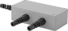
|
Junction Boxes bring multiple sensors together to create a single system. They’re often used in platform or hopper scales when multiple sensors need to work together to give a total weight reading.
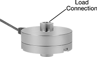
Round
 |  |
Button | Threaded Through Hole |
 |  |
Threaded Standoff | Threaded Stud |
 | |
Dual-Sided Threaded Stud |
Button—Round sensors with a button are often used to measure weight in packaging machinery and for pressure sensing in medical device prototypes.
Threaded Standoff—Round sensors with threaded standoffs have a threaded hole to connect to eye bolts, rod ends, and threaded rods. They’re commonly mounted upside-down between a tank and a leveling mount to weight material in small tanks and silos.
Dual-Sided Threaded Stud—Round sensors with a dual-sided threaded stud can monitor push-pull forces. For example, they might be used to test the durability of products that repeatedly fold and unfold.
Threaded Stud—Round sensors with a threaded stud screw into equipment.
Threaded Through Hole—Round sensors with a threaded through hole are also known as pancake load cells. They can be bolted to surfaces in any orientation and are commonly used to measure clamping forces.
IP66 Enclosure Rating— IP66 sensors stand up to spraying water.
Legal-for-Trade—Legal-for-trade sensors are NTEP approved for use with equipment that measures materials sold by weight.
Enclosure Rating—IP-rated sensors seal out dust.
Load Connection | Mounting Holes | ||||||||||||||||||||||||||||||||||||||||||||||||||||||||||||||||||||||||||||||||||||||||||||||||||
|---|---|---|---|---|---|---|---|---|---|---|---|---|---|---|---|---|---|---|---|---|---|---|---|---|---|---|---|---|---|---|---|---|---|---|---|---|---|---|---|---|---|---|---|---|---|---|---|---|---|---|---|---|---|---|---|---|---|---|---|---|---|---|---|---|---|---|---|---|---|---|---|---|---|---|---|---|---|---|---|---|---|---|---|---|---|---|---|---|---|---|---|---|---|---|---|---|---|---|---|
Wt. Cap. | Accuracy | Wt. Measuring Increments | Thread Size | Stud Lg. | Dia. | Ht. | Sensor Material | Temp. Range, ° F | Location | Fasteners Included | No. of | Diameter, mm | Thread Size | Enclosure Rating | Each | ||||||||||||||||||||||||||||||||||||||||||||||||||||||||||||||||||||||||||||||||||||
Measures Tension and Compression | |||||||||||||||||||||||||||||||||||||||||||||||||||||||||||||||||||||||||||||||||||||||||||||||||||
With 1 Threaded Through Hole | |||||||||||||||||||||||||||||||||||||||||||||||||||||||||||||||||||||||||||||||||||||||||||||||||||
| 550 lb.; 250 kg | ±4.4 oz., ±125 g | 0.01 lb., 0.01 kg | M10 × 1.5 mm | — | 2 15/16" | 1" | Alloy Steel | 0 to 140 | Top | No | 6 | 6.5 | — | — | 6131N25 | 0000000 | |||||||||||||||||||||||||||||||||||||||||||||||||||||||||||||||||||||||||||||||||||
With 2 Dual-Sided Threaded Studs | |||||||||||||||||||||||||||||||||||||||||||||||||||||||||||||||||||||||||||||||||||||||||||||||||||
| 220 lb.; 100 kg | ±2.2 lb., ±1 kg | 0.01 lb., 0.001 kg | M6 × 1 mm | 5/16" | 1" | 1 7/16" | Alloy Steel | 0 to 140 | — | — | — | — | — | — | 6131N24 | 00000000 | |||||||||||||||||||||||||||||||||||||||||||||||||||||||||||||||||||||||||||||||||||
With 2 Threaded Standoffs | |||||||||||||||||||||||||||||||||||||||||||||||||||||||||||||||||||||||||||||||||||||||||||||||||||
| 5,000 lb.; 2,265 kg | ±2.5 lb., ±1.13 kg | 0.1 lb., 0.1 kg | 1/2"-20 | — | 4 1/8" | 2 1/2" | Alloy Steel | -40 to 175 | — | — | — | — | — | — | 6131N16 | 00000000 | |||||||||||||||||||||||||||||||||||||||||||||||||||||||||||||||||||||||||||||||||||
| 10,000 lb.; 4,535 kg | ±5 lb., ±2.2 kg | 0.1 lb., 0.1 kg | 1/2"-20 | — | 4 1/8" | 2 1/2" | Alloy Steel | -40 to 175 | — | — | — | — | — | — | 6131N17 | 00000000 | |||||||||||||||||||||||||||||||||||||||||||||||||||||||||||||||||||||||||||||||||||
| 25,000 lb.; 11,335 kg | ±12.5 lb., ±5.7 kg | 1 lb., 1 kg | 3/4"-16 | — | 4 3/4" | 3 1/16" | Alloy Steel | -40 to 175 | — | — | — | — | — | — | 6131N18 | 00000000 | |||||||||||||||||||||||||||||||||||||||||||||||||||||||||||||||||||||||||||||||||||
Measures Compression Not Legal-for-Trade | |||||||||||||||||||||||||||||||||||||||||||||||||||||||||||||||||||||||||||||||||||||||||||||||||||
With 1 Button | |||||||||||||||||||||||||||||||||||||||||||||||||||||||||||||||||||||||||||||||||||||||||||||||||||
| 550 lb.; 250 kg | ±4.4 oz., ±125 g | 0.01 lb., 0.01 kg | — | — | 2 1/16" | 7/8" | Alloy Steel | 0 to 140 | Bottom | No | 4 | — | M5 × 0.8 mm | IP66 | 6131N21 | 000000 | |||||||||||||||||||||||||||||||||||||||||||||||||||||||||||||||||||||||||||||||||||
| 1,100 lb.; 500 kg | ±8.8 oz., ±250 g | 0.1 lb., 0.01 kg | — | — | 2 1/16" | 7/8" | Alloy Steel | 0 to 140 | Bottom | No | 4 | — | M5 × 0.8 mm | IP66 | 6131N22 | 000000 | |||||||||||||||||||||||||||||||||||||||||||||||||||||||||||||||||||||||||||||||||||
| 2,200 lb.; 1,000 kg | ±1.1 lb., ±500 g | 0.1 lb., 0.01 kg | — | — | 2 1/16" | 7/8" | Alloy Steel | 0 to 140 | Bottom | No | 4 | — | M5 × 0.8 mm | IP66 | 6131N19 | 000000 | |||||||||||||||||||||||||||||||||||||||||||||||||||||||||||||||||||||||||||||||||||
| 4,405 lb.; 2,000 kg | ±2.2 lb., ±1 kg | 0.1 lb., 0.1 kg | — | — | 3 1/4" | 1 3/4" | Alloy Steel | 0 to 140 | Bottom | No | 3 | — | M8 × 1.25 mm | IP66 | 6131N14 | 000000 | |||||||||||||||||||||||||||||||||||||||||||||||||||||||||||||||||||||||||||||||||||
| 11,020 lb.; 5,000 kg | ±5.5 lb., ±2.5 kg | 1 lb., 0.1 kg | — | — | 3 1/4" | 1 3/4" | Alloy Steel | 0 to 140 | Bottom | No | 3 | — | M8 × 1.25 mm | IP66 | 6131N15 | 000000 | |||||||||||||||||||||||||||||||||||||||||||||||||||||||||||||||||||||||||||||||||||
With 1 Threaded Stud | |||||||||||||||||||||||||||||||||||||||||||||||||||||||||||||||||||||||||||||||||||||||||||||||||||
| 110 lb.; 50 kg | ±8.8 oz., ±250 g | 0.01 lb., 0.001 kg | M12 × 1.75 mm | 15/16" | 2" | 2" | Alloy Steel | 0 to 140 | Bottom | No | 4 | — | M5 × 0.8 mm | IP66 | 6131N23 | 000000 | |||||||||||||||||||||||||||||||||||||||||||||||||||||||||||||||||||||||||||||||||||
|
Junction Boxes bring multiple sensors together to create a single system. They’re often used in platform or hopper scales when multiple sensors need to work together to give a total weight reading.
S-Shape
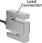 |
S-shape sensors with threaded through holes monitor and test tension in wires, cords, ropes, and harnesses. They’re often used in hanging scales.
IP67 Enclosure Rating— IP67 and IP68 sensors won’t fail if briefly submerged.
Legal-for-Trade—Legal-for-trade sensors are NTEP approved for use with equipment that measures materials sold by weight.
Enclosure Rating—IP-rated sensors seal out dust.
Wt. Cap. | Accuracy | Wt. Measuring Increments | Thread Size | Lg. | Wd. | Ht. | Sensor Material | Temp. Range, ° F | Enclosure Rating | Each | |||||||||||||||||||||||||||||||||||||||||||||||||||||||||||||||||||||||||||||||||||||||||
|---|---|---|---|---|---|---|---|---|---|---|---|---|---|---|---|---|---|---|---|---|---|---|---|---|---|---|---|---|---|---|---|---|---|---|---|---|---|---|---|---|---|---|---|---|---|---|---|---|---|---|---|---|---|---|---|---|---|---|---|---|---|---|---|---|---|---|---|---|---|---|---|---|---|---|---|---|---|---|---|---|---|---|---|---|---|---|---|---|---|---|---|---|---|---|---|---|---|---|---|
Measures Tension and Compression Legal-for-Trade | |||||||||||||||||||||||||||||||||||||||||||||||||||||||||||||||||||||||||||||||||||||||||||||||||||
With 2 Threaded Through Holes | |||||||||||||||||||||||||||||||||||||||||||||||||||||||||||||||||||||||||||||||||||||||||||||||||||
| 100 lb.; 45 kg | ±0.32 oz., ±9 g | 0.01 lb., 0.001 kg | 1/4"-28 | 2" | 7/16" | 2 3/8" | 17-4 PH Stainless Steel | -30 to 145 | IP67 | 6131N54 | 0000000 | ||||||||||||||||||||||||||||||||||||||||||||||||||||||||||||||||||||||||||||||||||||||||
| 100 lb.; 45 kg | ±0.32 oz., ±9 g | 0.01 lb., 0.001 kg | 1/4"-28 | 2" | 1/2" | 2 1/2" | Alloy Steel | -30 to 145 | IP67 | 6131N44 | 000000 | ||||||||||||||||||||||||||||||||||||||||||||||||||||||||||||||||||||||||||||||||||||||||
| 250 lb.; 113 kg | ±0.8 oz., ±23 g | 0.01 lb., 0.01 kg | 1/4"-28 | 2" | 7/16" | 2 3/8" | 17-4 PH Stainless Steel | -30 to 145 | IP67 | 6131N55 | 000000 | ||||||||||||||||||||||||||||||||||||||||||||||||||||||||||||||||||||||||||||||||||||||||
| 250 lb.; 113 kg | ±0.8 oz., ±23 g | 0.01 lb., 0.01 kg | 1/4"-28 | 2" | 1/2" | 2 1/2" | Alloy Steel | -30 to 145 | IP67 | 6131N45 | 000000 | ||||||||||||||||||||||||||||||||||||||||||||||||||||||||||||||||||||||||||||||||||||||||
| 500 lb.; 225 kg | ±1.6 oz., ±45 g | 0.01 lb., 0.01 kg | 1/2"-20 | 2" | 11/16" | 2 3/8" | 17-4 PH Stainless Steel | -30 to 145 | IP67 | 6131N56 | 000000 | ||||||||||||||||||||||||||||||||||||||||||||||||||||||||||||||||||||||||||||||||||||||||
| 500 lb.; 225 kg | ±1.6 oz., ±45 g | 0.01 lb., 0.01 kg | 1/2"-20 | 2" | 3/4" | 2 1/2" | Alloy Steel | -30 to 145 | IP67 | 6131N46 | 000000 | ||||||||||||||||||||||||||||||||||||||||||||||||||||||||||||||||||||||||||||||||||||||||
| 1,000 lb.; 450 kg | ±3.2 oz., ±90 g | 0.1 lb., 0.01 kg | 1/2"-20 | 2" | 11/16" | 2 3/8" | 17-4 PH Stainless Steel | -30 to 145 | IP67 | 6131N57 | 000000 | ||||||||||||||||||||||||||||||||||||||||||||||||||||||||||||||||||||||||||||||||||||||||
| 1,000 lb.; 450 kg | ±3.2 oz., ±90 g | 0.1 lb., 0.01 kg | 1/2"-20 | 2" | 3/4" | 2 1/2" | Alloy Steel | -30 to 145 | IP67 | 6131N47 | 000000 | ||||||||||||||||||||||||||||||||||||||||||||||||||||||||||||||||||||||||||||||||||||||||
| 2,000 lb.; 905 kg | ±6.4 oz., ±181 g | 0.1 lb., 0.1 kg | 1/2"-20 | 2" | 15/16" | 2 3/8" | 17-4 PH Stainless Steel | -30 to 145 | IP67 | 6131N58 | 000000 | ||||||||||||||||||||||||||||||||||||||||||||||||||||||||||||||||||||||||||||||||||||||||
| 2,000 lb.; 905 kg | ±6.4 oz., ±181 g | 0.1 lb., 0.1 kg | 1/2"-20 | 2" | 1" | 2 1/2" | Alloy Steel | -30 to 145 | IP67 | 6131N48 | 000000 | ||||||||||||||||||||||||||||||||||||||||||||||||||||||||||||||||||||||||||||||||||||||||
| 2,500 lb.; 1,130 kg | ±8 oz., ±226 g | 0.1 lb., 0.1 kg | 1/2"-20 | 2" | 15/16" | 2 3/8" | 17-4 PH Stainless Steel | -30 to 145 | IP67 | 6131N59 | 000000 | ||||||||||||||||||||||||||||||||||||||||||||||||||||||||||||||||||||||||||||||||||||||||
| 2,500 lb.; 1,130 kg | ±8 oz., ±226 g | 0.1 lb., 0.1 kg | 1/2"-20 | 2" | 1" | 2 1/2" | Alloy Steel | -30 to 145 | IP67 | 6131N49 | 000000 | ||||||||||||||||||||||||||||||||||||||||||||||||||||||||||||||||||||||||||||||||||||||||
| 3,000 lb.; 1,360 kg | ±9.6 oz., ±272 g | 0.1 lb., 0.1 kg | 1/2"-20 | 3" | 15/16" | 3 7/8" | 17-4 PH Stainless Steel | -30 to 145 | IP67 | 6131N61 | 000000 | ||||||||||||||||||||||||||||||||||||||||||||||||||||||||||||||||||||||||||||||||||||||||
| 3,000 lb.; 1,360 kg | ±9.6 oz., ±272 g | 0.1 lb., 0.1 kg | 1/2"-20 | 3" | 1" | 4" | Alloy Steel | -30 to 145 | IP67 | 6131N51 | 000000 | ||||||||||||||||||||||||||||||||||||||||||||||||||||||||||||||||||||||||||||||||||||||||
| 5,000 lb.; 2,265 kg | ±1 lb., ±453 g | 0.1 lb., 0.1 kg | 3/4"-16 | 3" | 15/16" | 3 7/8" | 17-4 PH Stainless Steel | -30 to 145 | IP67 | 6131N62 | 000000 | ||||||||||||||||||||||||||||||||||||||||||||||||||||||||||||||||||||||||||||||||||||||||
| 5,000 lb.; 2,265 kg | ±1 lb., ±453 g | 0.1 lb., 0.1 kg | 3/4"-16 | 3" | 1" | 4" | Alloy Steel | -30 to 145 | IP67 | 6131N52 | 000000 | ||||||||||||||||||||||||||||||||||||||||||||||||||||||||||||||||||||||||||||||||||||||||
| 10,000 lb.; 4,535 kg | ±2 lb., ±907 g | 1 lb., 0.1 kg | 3/4"-16 | 2 15/16" | 1 3/16" | 3 7/8" | 17-4 PH Stainless Steel | -30 to 145 | IP67 | 6131N63 | 000000 | ||||||||||||||||||||||||||||||||||||||||||||||||||||||||||||||||||||||||||||||||||||||||
| 10,000 lb.; 4,535 kg | ±2 lb., ±907 g | 1 lb., 0.1 kg | 3/4"-16 | 3" | 1" | 4" | Alloy Steel | -30 to 145 | IP67 | 6131N53 | 000000 | ||||||||||||||||||||||||||||||||||||||||||||||||||||||||||||||||||||||||||||||||||||||||
|
Junction Boxes bring multiple sensors together to create a single system. They’re often used in platform or hopper scales when multiple sensors need to work together to give a total weight reading.
Cylinder
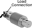 |
Cylinder sensors are commonly used for platform, belt, hopper, and packaging scales. They resist corrosion and frequent washdowns.
IP68 Enclosure Rating— IP67 and IP68 sensors won’t fail if briefly submerged.
Legal-for-Trade—Legal-for-trade sensors are NTEP approved for use with equipment that measures materials sold by weight.
Enclosure Rating—IP-rated sensors seal out dust.
Wt. Cap. | Accuracy | Wt. Measuring Increments | Thread Size | Dia. | Lg. | Sensor Material | Temp. Range, ° F | Enclosure Rating | Each | ||||||||||||||||||||||||||||||||||||||||||||||||||||||||||||||||||||||||||||||||||||||||||
|---|---|---|---|---|---|---|---|---|---|---|---|---|---|---|---|---|---|---|---|---|---|---|---|---|---|---|---|---|---|---|---|---|---|---|---|---|---|---|---|---|---|---|---|---|---|---|---|---|---|---|---|---|---|---|---|---|---|---|---|---|---|---|---|---|---|---|---|---|---|---|---|---|---|---|---|---|---|---|---|---|---|---|---|---|---|---|---|---|---|---|---|---|---|---|---|---|---|---|---|
Measures Compression Legal-for-Trade | |||||||||||||||||||||||||||||||||||||||||||||||||||||||||||||||||||||||||||||||||||||||||||||||||||
With 3 Through Holes | |||||||||||||||||||||||||||||||||||||||||||||||||||||||||||||||||||||||||||||||||||||||||||||||||||
| 65 lb.; 30 kg | ±0.2 oz., ±6 g | 0.01 lb., 0.01 kg | M8 | 1 1/2" | 4 3/4" | 17-4 PH Stainless Steel | -30 to 145 | IP68 | 6131N75 | 0000000 | |||||||||||||||||||||||||||||||||||||||||||||||||||||||||||||||||||||||||||||||||||||||||
| 220 lb.; 100 kg | ±0.7 oz., ±20 g | 0.1 lb., 0.01 kg | M8 | 1 1/2" | 4 3/4" | 17-4 PH Stainless Steel | -30 to 145 | IP68 | 6131N76 | 000000 | |||||||||||||||||||||||||||||||||||||||||||||||||||||||||||||||||||||||||||||||||||||||||
| 440 lb.; 200 kg | ±1.4 oz., ±40 g | 0.1 lb., 0.01 kg | M8 | 1 1/2" | 4 3/4" | 17-4 PH Stainless Steel | -30 to 145 | IP68 | 6131N77 | 000000 | |||||||||||||||||||||||||||||||||||||||||||||||||||||||||||||||||||||||||||||||||||||||||
| 1,100 lb.; 500 kg | ±3.5 oz., ±100 g | 0.1 lb., 0.1 kg | M10 | 1 1/2" | 4 3/4" | 17-4 PH Stainless Steel | -30 to 145 | IP68 | 6131N78 | 000000 | |||||||||||||||||||||||||||||||||||||||||||||||||||||||||||||||||||||||||||||||||||||||||
|
Junction Boxes bring multiple sensors together to create a single system. They’re often used in platform or hopper scales when multiple sensors need to work together to give a total weight reading.
