


For Use With For Use With |
|---|
|
Maximum Inlet Pressure Maximum Inlet Pressure |
|---|
|
Valve Function Valve Function |
|---|
|
Outlet Pressure Outlet Pressure |
|---|
Body Material Body Material |
|---|
|
|
Maximum Outlet Pressure Gauge Maximum OutletPressure Gauge |
|---|
|
|
Outlet Thread Type Outlet Thread Type |
|---|
|
Flow Coefficient (Cv) Flow Coefficient (Cv) |
|---|
|
|
|
Valve Type Valve Type |
|---|
|
Minimum Temperature Minimum Temperature |
|---|
|
Diaphragm Material Diaphragm Material |
|---|
|
REACH (Registration, Evaluation, Authorization and Restriction of Chemicals) REACH (Registration,Evaluation, Authorization and Restriction of Chemicals) |
|---|
|
RoHS (Restriction of Hazardous Substances) RoHS (Restriction ofHazardous Substances) |
|---|
|
About Pressure-Relief Valves
More
About Air Preparation
More
About Backflow-Prevention Valves
More
About Gas Regulators
More
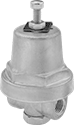
Cleaned and Bagged Pressure-Regulating Valves for Air and Inert Gas
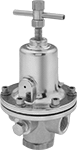
- For Use With: Nitrogen, Oxygen, Argon, Helium, Neon
- Temperature Range: -40° to 165° F
Often used for oxygen service and other high-purity applications, these valves are cleaned and bagged to meet CGA G-4.1 standards to prevent contamination. They automatically reduce a high, variable inlet pressure to a lower, stable outlet pressure. Adjust the outlet pressure within the range. Valves have two gauge ports. They are no-bleed style, so they keep process gases contained in the valve.
![]() For technical drawings and 3-D models, click on a part number.
For technical drawings and 3-D models, click on a part number.
Inlet | Outlet | Gauge Port | ||||||||
|---|---|---|---|---|---|---|---|---|---|---|
| Pipe Size | Location | Max. Pressure, psi | Pipe Size | Location | Pipe Size | Location | End-to-End Lg. | Choose an Outlet Pressure Range, psi | Each | |
NPT Female | ||||||||||
Brass Body—Buna-N Diaphragm and Fluoroelastomer Seal | ||||||||||
| 1/2 | Side | 500 | 1/2 | Side | 1/4 | Side | 2 13/16" | 00000000 | 0000000 | |
| 3/4 | Side | 500 | 3/4 | Side | 1/4 | Side | 3 5/16" | 00000000 | 000000 | |
| 1 | Side | 500 | 1 | Side | 1/4 | Side | 3 5/16" | 00000000 | 000000 | |
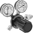
Miniature Ultra-High-Pressure-Regulating Valves for Water, Air, and Inert Gas
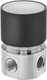
- For Use With: Water, Air, Argon
- Temperature Range: -15° to 165° F
For extremely high-pressure applications in tight spots, these valves handle the same inlet pressures as other ultra-high-pressure-regulating valves within a smaller footprint. They automatically reduce a high, variable inlet pressure to a lower, stable outlet pressure. Adjust the outlet pressure within the range. All have two gauge ports. Body is nickel-plated aluminum for good corrosion resistance. Valves are no-bleed style, so they keep the process gas contained within the valve.
![]() For technical drawings and 3-D models, click on a part number.
For technical drawings and 3-D models, click on a part number.
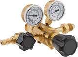
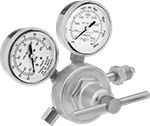
Tank-Mount Pressure-Regulating Valves for Air and Inert Gas
- For Use With: See Table
- Temperature Range: -20° to 120° F
These valves automatically reduce a high inlet pressure from compressed gas tanks to a lower, stable outlet pressure. All have Compressed Gas Association (CGA) numbered inlet fittings for secure connections to compressed gas tanks. Choose a valve with the same CGA number as your tank and other system components. Valves have a gauge to monitor outlet pressure and a gauge to monitor inlet pressure from the tank.
Choose a valve with a maximum outlet pressure that’s approximately twice your application’s normal operating pressure. Your operating pressure should never exceed 75% of the valve’s maximum outlet pressure.
Single-stage valves reduce pressure in one step, which causes the outlet pressure to fluctuate slightly as you empty the tank. They’re best for applications where a constant outlet pressure isn’t critical.
Two-stage valves progressively reduce pressure over two steps for more consistent outlet pressure at all times. They’re often used in applications that require a constant outlet pressure regardless of the tank level.
Valves with a brass body have a longer service life than valves with a brass and steel body.
Valves with a stainless steel diaphragm can withstand harsh environments.
Valves with flared tube outlet fittings form a tight seal on metal tubing.
Inlet | Outlet | Material | ||||||||||
|---|---|---|---|---|---|---|---|---|---|---|---|---|
| CGA Number | Location | Thread Direction | Pressure Gauge Range, psi | Location | Thread Direction | Pressure Range, psi | Pressure Adjustment Method | Body | Seal | Diaphragm | Each | |
For Use With Argon, Helium, and Nitrogen | ||||||||||||
37° Flared UNF Male Outlet × NGO Male Inlet | ||||||||||||
| CGA 580 | Side | Right Hand | 0 to 4,000 | Side | Right Hand | 10 to 200 | T-Handle | Brass | Polyurethane | Neoprene/Nylon | 00000000 | 0000000 |
45° Flared UN/UNF (SAE 45°) Male Outlet × NGO Male Inlet | ||||||||||||
| CGA 580 | Side | Right Hand | 0 to 4,000 | Side | Right Hand | 0 to 250 | T-Handle | Brass | PTFE | Neoprene | 00000000 | 000000 |
| CGA 580 | Side | Right Hand | 0 to 4,000 | Side | Right Hand | 0 to 500 | T-Handle | Brass | PTFE | Neoprene | 00000000 | 000000 |
5/8"-18 UNF Female Outlet × NGO Male Inlet | ||||||||||||
| CGA 580 | Side | Right Hand | 0 to 4,000 | Side | Right Hand | 0 to 125 | T-Handle | Brass | PTFE | Stainless Steel | 00000000 | 000000 |
| CGA 580 | Side | Right Hand | 0 to 4,568 | Side | Right Hand | 5 to 150 | Knob | Brass | Polyester/Polyurethane | Neoprene/Nylon | 00000000 | 000000 |
9/16"-18 UNF Male Outlet × NGO Male Inlet | ||||||||||||
| CGA 580 | Side | Right Hand | 0 to 4,000 | Side | Right Hand | 0 to 50 | T-Handle | Brass | PTFE | Neoprene | 00000000 | 000000 |
| CGA 580 | Side | Right Hand | 0 to 4,000 | Side | Right Hand | 0 to 125 | T-Handle | Brass | PTFE | Rubber | 0000000 | 000000 |
| CGA 580 | Side | Right Hand | 0 to 4,000 | Side | Right Hand | 0 to 145 | Knob | Brass/Steel | PTFE | Rubber | 0000000 | 000000 |
| CGA 580 | Side | Right Hand | 0 to 4,000 | Side | Right Hand | 0 to 200 | T-Handle | Brass | PTFE | Rubber | 0000000 | 000000 |
Inlet | Outlet | Material | ||||||||||
|---|---|---|---|---|---|---|---|---|---|---|---|---|
| CGA Number | Location | Thread Direction | Pressure Gauge Range, psi | Location | Thread Direction | Pressure Range, psi | Pressure Adjustment Method | Body | Seal | Diaphragm | Each | |
For Use With Argon, Helium, and Nitrogen | ||||||||||||
1/4 NPT Female Outlet × NGO Male Inlet | ||||||||||||
| CGA 580 | Side | Right Hand | 0 to 4,000 | Side | Right Hand | 0 to 250 | T-Handle | Brass | PTFE | Neoprene | 00000000 | 0000000 |
| CGA 580 | Side | Right Hand | 0 to 4,000 | Side | Right Hand | 0 to 250 | T-Handle | Brass | PTFE | Stainless Steel | 00000000 | 000000 |
5/8"-18 UNF Female Outlet × NGO Male Inlet | ||||||||||||
| CGA 580 | Side | Right Hand | 0 to 4,000 | Side | Right Hand | 0 to 50 | T-Handle | Brass | PTFE | Neoprene | 00000000 | 000000 |
| CGA 580 | Side | Right Hand | 0 to 4,000 | Side | Right Hand | 0 to 50 | T-Handle | Brass | PTFE | Stainless Steel | 0000000 | 000000 |
| CGA 580 | Side | Right Hand | 0 to 4,000 | Side | Right Hand | 0 to 125 | T-Handle | Brass | PTFE | Stainless Steel | 0000000 | 000000 |
| CGA 580 | Side | Right Hand | 0 to 4,000 | Side | Right Hand | 0 to 125 | T-Handle | Brass/Steel | PTFE | Rubber | 0000000 | 000000 |
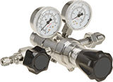
High-Purity Tank-Mount Pressure-Regulating Valves for Inert Gas
- For Use With: See Table
- Temperature Range: -20° to 120° F
Reduce contaminants in research sample systems, emission monitoring systems, chromatography, and other high-purity applications that use argon, helium, nitrogen, or carbon dioxide. These valves have a 316 stainless steel and brass body with a smooth finish to reduce dust collection and internal components designed to protect the seal and diaphragm from contamination. They automatically reduce a high inlet pressure from compressed gas tanks to a lower, stable outlet pressure. All have Compressed Gas Association (CGA) numbered inlet fittings for secure connections to compressed gas tanks. Choose a valve with the same CGA number as your tank and other system components. Outlet fittings are Swagelok® for a leak-free seal around hard metal tubing in high-pressure lines. Also known as instrumentation fittings, Swagelok® fittings are compatible with Parker A-Lok, Gyrolok, Bilok, and Tylok fittings. Valves have a gauge to monitor outlet pressure and a gauge to monitor inlet pressure from the tank.
Choose a valve with a maximum outlet pressure that’s approximately twice your application’s normal operating pressure. Your operating pressure should never exceed 75% of the valve’s maximum outlet pressure.
Single-stage valves reduce pressure in one step, which causes the outlet pressure to fluctuate slightly as you empty the tank. They’re best for applications where a constant outlet pressure isn’t critical.
Two-stage valves progressively reduce pressure over two steps for more consistent outlet pressure at all times. They’re often used in applications that require a constant outlet pressure regardless of the tank level.
Chrome-plated valves add a layer of corrosion resistance.
Inlet | Outlet | |||||||||
|---|---|---|---|---|---|---|---|---|---|---|
| CGA Number | Location | Thread Direction | Pressure Gauge Range, psi | Stage | For Tube OD | Location | Pressure Range, psi | Pressure Adjustment Method | Each | |
Swagelok® Female Outlet × NGO Male Inlet | ||||||||||
Brass Body—316 Stainless Steel Diaphragm and PTFE Seal | ||||||||||
| CGA 580 | Side | Right Hand | 0 to 4,000 | Single | 1/4" | Side | 0 to 15 | Knob | 0000000 | 0000000 |
| CGA 580 | Side | Right Hand | 0 to 4,000 | Single | 1/4" | Side | 0 to 125 | Knob | 0000000 | 000000 |
| CGA 580 | Side | Right Hand | 0 to 4,000 | Single | 1/4" | Side | 0 to 500 | Knob | 0000000 | 000000 |
| CGA 580 | Side | Right Hand | 0 to 4,000 | Two | 1/4" | Side | 0 to 15 | Knob | 0000000 | 000000 |
| CGA 580 | Side | Right Hand | 0 to 4,000 | Two | 1/4" | Side | 0 to 50 | Knob | 0000000 | 000000 |
| CGA 580 | Side | Right Hand | 0 to 4,000 | Two | 1/4" | Side | 0 to 125 | Knob | 0000000 | 000000 |
| CGA 580 | Side | Right Hand | 0 to 4,000 | Two | 1/4" | Side | 0 to 250 | Knob | 0000000 | 000000 |
Chrome-Plated Brass Body—316 Stainless Steel Diaphragm and PTFE Seal | ||||||||||
| CGA 580 | Side | Right Hand | 0 to 4,000 | Two | 1/4" | Side | 0 to 50 | Knob | 0000000 | 000000 |
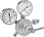
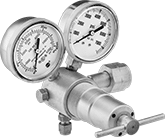
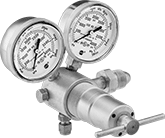
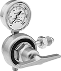
Tank-Mount High-Pressure-Regulating Valves for Air and Inert Gas
- For Use With: See Table
- Temperature Range: -20° to 120° F
Often used for pressure-vessel testing and other high-pressure applications, these valves can handle at least seven times the outlet pressure of standard tank-mount pressure-regulating valves. They automatically reduce a high inlet pressure from compressed gas tanks to a lower, stable outlet pressure. All have Compressed Gas Association (CGA) numbered inlet fittings for secure connections to compressed gas tanks. Choose a valve with the same CGA number as your tank and other system components. Outlet fittings are Swagelok® for a leak-free seal around hard metal tubing in high-pressure lines. Also known as instrumentation fittings, Swagelok® fittings are compatible with Parker A-Lok, Gyrolok, Bilok, and Tylok fittings. Valves have a gauge to monitor outlet pressure and a gauge to monitor inlet pressure from the tank. They are single stage and reduce pressure in one step, which causes the outlet pressure to fluctuate slightly as you empty the tank.
Choose a valve with a maximum outlet pressure that’s approximately twice your application’s normal operating pressure. Your operating pressure should never exceed 75% of the valve’s maximum outlet pressure.
Inlet | Outlet | Material | |||||||||||
|---|---|---|---|---|---|---|---|---|---|---|---|---|---|
| CGA Number | Location | Thread Direction | Pressure Gauge Range, psi | Stage | For Tube OD | Location | Pressure Range, psi | Pressure Adjustment Method | Shape | Body | Seal | Each | |
NGO Female Inlet × Swagelok® Female Outlet | |||||||||||||
| CGA 677 | Side | Left Hand | 0 to 7,500 | Single | 1/4" | Bottom | 300 to 4,500 | T-Handle | 90° Elbow | Brass | PCTFE | 0000000 | 000000000 |
NGO Male Inlet × Swagelok® Female Outlet | |||||||||||||
| CGA 580 | Side | Right Hand | 0 to 4,000 | Single | 1/4" | Bottom | 100 to 1,500 | T-Handle | 90° Elbow | Brass | PCTFE | 0000000 | 000000 |
| CGA 580 | Side | Right Hand | 0 to 4,000 | Single | 1/4" | Bottom | 200 to 3,000 | T-Handle | 90° Elbow | Brass | PCTFE | 0000000 | 000000 |
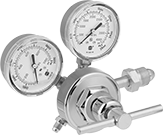
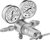
Easy-Read Tank-Mount Pressure-Regulating Valves with Flowmeter for Inert Gas
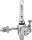
- For Use With: See Table
Flowmeters let you see the gas flow rate from a distance. These valves automatically reduce a high inlet pressure from compressed gas tanks to a lower, stable outlet pressure. All have Compressed Gas Association (CGA) numbered inlet fittings for secure connections to compressed gas tanks. Choose a valve with the same CGA number as your tank and other system components. They have a gauge for monitoring inlet pressure from the tank.
Single-stage valves reduce pressure in one step, which causes the outlet pressure to fluctuate slightly as you empty the tank. They’re best for applications where a constant outlet pressure isn’t critical.
Two-stage valves progressively reduce pressure over two steps for more consistent outlet pressure at all times. They’re often used in applications that require a constant outlet pressure regardless of the tank level.
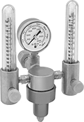
Valves with one flowmeter are for one piece of equipment on a tank. The flowmeter has a single scale.
Valve with two flowmeters lets you simultaneously run two pieces of equipment from one tank. Both flowmeters have a dual scale.
Adapters (sold separately) change 5/8"-18 outlets to 9/16"-18 male connections, and vice versa.
Inlet | Outlet | Material | ||||||||||||
|---|---|---|---|---|---|---|---|---|---|---|---|---|---|---|
| CGA Number | Location | Thread Direction | Pressure Gauge Range, psi | Stage | Thread Size | Location | Thread Direction | Flow Range, scfh | Number of Flowmeters | Body | Seal | Diaphragm | Each | |
UNF Female Outlet × NGO Male Inlet | ||||||||||||||
| CGA 580 | Side | Right Hand | 0 to 4,000 | Single | 5/8"-18 | Side | Right Hand | 0 to 70 | 1 | Brass | PTFE | Neoprene | 00000000 | 0000000 |
| Optional Adapter | 00000000 | Each | 000000 |
Inlet | Outlet | Material | ||||||||||||
|---|---|---|---|---|---|---|---|---|---|---|---|---|---|---|
| CGA Number | Location | Thread Direction | Pressure Gauge Range, psi | Stage | Thread Size | Location | Thread Direction | Flow Range, scfh | Number of Flowmeters | Body | Seal | Diaphragm | Each | |
UNF Female Outlet × NGO Female Inlet | ||||||||||||||
| CGA 320 | Side | Right Hand | 0 to 3,000 | Single | 5/8"-18 | Side | Right Hand | 0 to 50 (Argon), 0 to 38 (Argon/Carbon Dioxide Blend) | 1 | Brass | PTFE | Neoprene | 000000000 | 0000000 |
| Optional Adapter | 00000000 | Each | 000000 |
Inlet | Outlet | Material | ||||||||||||
|---|---|---|---|---|---|---|---|---|---|---|---|---|---|---|
| CGA Number | Location | Thread Direction | Pressure Gauge Range, psi | Stage | Thread Size | Location | Thread Direction | Flow Range, scfh | Number of Flowmeters | Body | Seal | Diaphragm | Each | |
UNF Female Outlet × NGO Male Inlet | ||||||||||||||
| CGA 580 | Side | Right Hand | 0 to 3,000 | Two | 5/8"-18 | Side | Right Hand | 0 to 18 (Argon), 0 to 50 (Helium) | 1 | Brass | PTFE | Neoprene | 000000000 | 0000000 |
| CGA 580 | Side | Right Hand | 0 to 3,000 | Two | 5/8"-18 | Side | Right Hand | 0 to 65 (Argon), 0 to 200 (Helium) | 1 | Brass | PTFE | Neoprene | 000000000 | 000000 |
| CGA 580 | Side | Right Hand | 0 to 4,000 | Single | 5/8"-18 | Side | Right Hand | 0 to 45 (Argon), 0 to 140 (Helium) | 1 | Brass | PTFE | Neoprene | 00000000 | 000000 |
| CGA 580 | Side | Right Hand | 0 to 4,000 | Single | 5/8"-18 | Side | Right Hand | 0 to 45 (Argon), 0 to 140 (Helium) | 2 | Brass | PTFE | Neoprene | 0000000 | 000000 |
| Optional Adapter | 00000000 | Each | 000000 |
Inlet | Outlet | Material | ||||||||||||
|---|---|---|---|---|---|---|---|---|---|---|---|---|---|---|
| CGA Number | Location | Thread Direction | Pressure Gauge Range, psi | Stage | Thread Size | Location | Thread Direction | Flow Range, scfh | Number of Flowmeters | Body | Seal | Diaphragm | Each | |
UNF Female Outlet × NGO Male Inlet | ||||||||||||||
| CGA 580 | Side | Right Hand | 0 to 3,000 | Single | 5/8"-18 | Side | Right Hand | 0 to 40 (Argon), 0 to 40 (Argon/Carbon Dioxide Blend), 0 to 150 (Helium) to150 | 1 | Brass | PTFE | Neoprene | 000000000 | 0000000 |
| CGA 580 | Side | Right Hand | 0 to 3,000 | Two | 5/8"-18 | Side | Right Hand | 0 to 40 (Argon), 0 to 40 (Argon/Carbon Dioxide Blend), 0 to 150 (Helium) to150 | 1 | Brass | PTFE | Neoprene | 000000000 | 000000 |
| Optional Adapter | 00000000 | Each | 000000 |
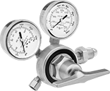
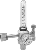
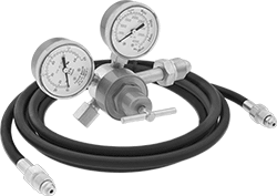
Tank-Mount Pressure-Regulating Valves with Flowmeter for Inert Gas
- For Use With: See Table
- Temperature Range: -20° to 120° F
Commonly used in TIG welding where gas flow/coverage is a concern, these valves measure the gas flow rate in addition to regulating pressure. They automatically reduce a high inlet pressure from compressed gas tanks to a lower, stable outlet pressure. All have Compressed Gas Association (CGA) numbered inlet fittings for secure connections to compressed gas tanks. Choose a valve with the same CGA number as your tank and other system components. Valves have a gauge to monitor the outlet flow rate and a second gauge to monitor inlet pressure from the tank. They are single stage and reduce pressure in one step, which causes the outlet pressure to fluctuate slightly as you empty the tank.
Inlet | Outlet | Material | |||||||||||||
|---|---|---|---|---|---|---|---|---|---|---|---|---|---|---|---|
| CGA Number | Location | Thread Direction | Pressure Gauge Range, psi | Stage | Thread Size | Location | Thread Direction | Flow Range, scfh | Flow Gauge Included | Body | Seal | Diaphragm | Includes | Each | |
UNF Female Outlet × NGO Male Inlet | |||||||||||||||
| CGA 580 | Side | Right Hand | 0 to 4,000 | Single | 5/8"-18 | Side | Right Hand | 0 to 60 | Yes | Brass | PTFE | Neoprene | __ | 0000000 | 0000000 |
| CGA 580 | Side | Right Hand | 0 to 4,000 | Single | 5/8"-18 | Side | Right Hand | 0 to 60 | Yes | Brass | PTFE | Neoprene | 10-ft. long, 3/16" dia. hose with 5/8"-18 male fittings on both ends | 0000000 | 000000 |
| CGA 580 | Side | Right Hand | 0 to 4,000 | Single | 5/8"-18 | Side | Right Hand | 0 to 100 | Yes | Brass | PTFE | Neoprene | __ | 0000000 | 000000 |
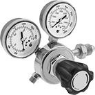
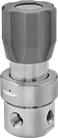
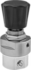
Panel-Mount Ultra-High-Pressure-Regulating Valves for Air and Inert Gas
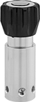
- For Use With: Air, Nitrogen, Argon, Helium
- Temperature Range: -40° to 165° F
These valves are rated for inlet pressures up to 6,000 psi. They automatically reduce a high, variable inlet pressure to a lower, stable outlet pressure. Adjust the outlet pressure within the range. Threads below the adjustment knob and an included mounting bracket let you install these valves in instrument panels. They have two gauge ports. An internal strainer traps debris.
![]() For technical drawings and 3-D models, click on a part number.
For technical drawings and 3-D models, click on a part number.
Inlet | Outlet | Gauge Port | ||||||||||
|---|---|---|---|---|---|---|---|---|---|---|---|---|
| Pipe Size | Location | Max. Pressure, psi | Pipe Size | Location | Pipe Size | Location | End-to-End Lg. | Panel Cutout Dia. | Specifications Met | Choose an Outlet Pressure Range, psi | Each | |
NPT Female | ||||||||||||
Brass Body—Polyimide Seal | ||||||||||||
| 1/4 | Side | 6,000 | 1/4 | Side | 1/4 | Side | 2 1/8" | 2 1/4" | ASME B31.3 | 0000000 | 0000000 | |
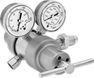
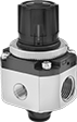
Panel-Mount High-Pressure-Regulating Valves for Air and Inert Gas
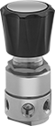
- For Use With: Air, Nitrogen, Argon, Helium
- Temperature Range: -40° to 165° F
Withstand inlet pressures up to 3,500 psi. These valves automatically reduce a high, variable inlet pressure to a lower, stable outlet pressure. Adjust the outlet pressure within the range. Valves have threads below the adjustment knob and come with a panel-mount nut. All have two gauge ports. An internal strainer traps debris.
![]() For technical drawings and 3-D models, click on a part number.
For technical drawings and 3-D models, click on a part number.
Inlet | Outlet | Gauge Port | ||||||||||
|---|---|---|---|---|---|---|---|---|---|---|---|---|
| Pipe Size | Location | Max. Pressure, psi | Pipe Size | Location | Pipe Size | Location | End-to-End Lg. | Panel Cutout Dia. | Specifications Met | Choose an Outlet Pressure Range, psi | Each | |
NPT Female | ||||||||||||
Brass Body—316 Stainless Steel Diaphragm and PTFE Seal | ||||||||||||
| 1/4 | Side | 3,500 | 1/4 | Side | 1/4 | Side | 2" | 1 3/8" | ASME B31.3 | 0000000 | 0000000 | |
Cleaned and Bagged Panel-Mount Pressure-Regulating Valves for Air and Inert Gas
- For Use With: Air, Nitrogen, Argon, Helium
- Temperature Range: -40° to 160° F
Commonly used for oxygen service and other high-purity applications, these valves come cleaned and bagged to prevent contamination. All automatically reduce a high, variable inlet pressure to a lower, stable outlet pressure. Adjust the outlet pressure within the range. Valves have threads below the adjustment knob and come with a panel-mount nut. They can also be surface mounted. All have two gauge ports. Body is 316 stainless steel for exceptional corrosion resistance. Valves are no-bleed style, so they keep process gases contained in the valve.
![]() For technical drawings and 3-D models, click on a part number.
For technical drawings and 3-D models, click on a part number.
Inlet | Outlet | Gauge Port | |||||||||
|---|---|---|---|---|---|---|---|---|---|---|---|
| Pipe Size | Location | Max. Pressure, psi | Pipe Size | Location | Pipe Size | Connection | End-to-End Lg. | Panel Cutout Dia. | Choose an Outlet Pressure Range, psi | Each | |
NPT Female | |||||||||||
316 Stainless Steel Body—316 Stainless Steel Diaphragm and PCTFE Seal | |||||||||||
| 1/4 | Side | 3,500 | 1/4 | Side | 1/4 | NPT Female | 2" | 1.42" | 0000000 | 0000000 | |
316 Stainless Steel Body—Nickel Alloy Diaphragm and PCTFE Seal | |||||||||||
| 1/2 | Side | 300 | 1/2 | Side | 1/4 | NPT Female | 2 1/2" | 1.56" | 0000000 | 000000 | |
Clean Room Panel-Mount Pressure-Regulating Valves for Air and Inert Gas
- For Use With:
Relieving: Air, Nitrogen
Nonrelieving: Air, Argon, Carbon Dioxide, Nitrogen - Temperature Range: 32° to 140° F
Maintain contaminant-free standards in clean room environments. These valves come cleaned and bagged to Fed. Spec. Class 100 and ISO Class 5 clean room standards and have a 316 stainless steel body with a smooth finish to resist dust collection. They automatically reduce a high, variable inlet pressure to a lower, stable output pressure. Valves have threads below the adjustment knob and come with a panel-mount nut. Adjust the outlet pressure within the range.
Gauge ports let you attach a pressure gauge.
Nonrelieving valves do not exhaust excess downstream pressure.
![]() For technical drawings and 3-D models, click on a part number.
For technical drawings and 3-D models, click on a part number.
Regulators | ||||||||||||||
|---|---|---|---|---|---|---|---|---|---|---|---|---|---|---|
Inlet | Outlet | Gauge Port | Mounting Brackets | |||||||||||
| Pipe Size | Location | Max. Pressure, psi | Pipe Size | Location | Pressure Range, psi | Pipe Size | Location | End-to-End Lg. | Panel Cutout Dia. | Environmental Rating | Each | Each | ||
NPT Female | ||||||||||||||
316 Stainless Steel Body—Fluoroelastomer Diaphragm and Seal | ||||||||||||||
| 1/8 | Side | 145 | 1/8 | Side | 7 to 102 | 1/4 | Side | 1.700" | 1.2" | Fed. Std. Class 100, ISO Class 5 | 0000000 | 0000000 | 0000000 | 00000 |
| 1/4 | Side | 145 | 1/4 | Side | 7 to 102 | 1/4 | Side | 1.700" | 1.2" | Fed. Std. Class 100, ISO Class 5 | 0000000 | 000000 | 0000000 | 0000 |
| 1/4 | Side | 145 | 1/4 | Side | 7 to 102 | 1/4 | Side | 2.280" | 1.44" | Fed. Std. Class 100, ISO Class 5 | 0000000 | 000000 | 0000000 | 00000 |
| 3/8 | Side | 145 | 3/8 | Side | 7 to 102 | 1/4 | Side | 2.280" | 1.44" | Fed. Std. Class 100, ISO Class 5 | 0000000 | 000000 | 0000000 | 00000 |
| 1/2 | Side | 145 | 1/2 | Side | 7 to 102 | 1/4 | Side | 2.280" | 1.44" | Fed. Std. Class 100, ISO Class 5 | 0000000 | 000000 | 0000000 | 00000 |
| Pressure Gauge | 0000000 | Each | 000000 |
Extended-Life Pressure-Regulating Valves for Cryogenic Liquids
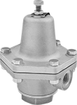
- For Use With: Liquid Argon, Liquid Carbon Dioxide, Liquid Nitrogen, Liquid Oxygen
- Temperature Range: -320° to 150° F
For a longer service life than standard valves for cryogenic liquids, these have a durable bronze body. All are cleaned and bagged for oxygen service and other high-purity applications. They automatically reduce a high, variable inlet pressure to a lower, stable outlet pressure. Adjust the outlet pressure within the range. Valves are designed to withstand the extreme cold of liquid argon, liquid carbon dioxide, liquid nitrogen, and liquid oxygen. They have an internal strainer to trap debris.
![]() For technical drawings and 3-D models, click on a part number.
For technical drawings and 3-D models, click on a part number.
Inlet | Outlet | |||||||
|---|---|---|---|---|---|---|---|---|
| Pipe Size | Location | Max. Pressure, psi | Pipe Size | Location | End-to-End Lg. | Choose an Outlet Pressure Range, psi | Each | |
NPT Female | ||||||||
Bronze Body—Bronze Diaphragm and PTFE Seal with Internal Strainer | ||||||||
| 1/4 | Side | 400 | 1/4 | Side | 3 1/16" | 00000000 | 0000000 | |
| 1/2 | Side | 400 | 1/2 | Side | 4 1/2" | 00000000 | 000000 | |
| 1 | Side | 400 | 1 | Side | 5 7/8" | 00000000 | 00000000 | |
Tank-Mount Pressure-Regulating Valves for Cryogenic Cylinders
- For Use With: See Table
- Temperature Range: -20° to 120° F
Automatically reduce a high inlet pressure from compressed gas tanks to a lower, stable outlet pressure. These valves can remove gases from liquid cryogenic cylinders. They have Compressed Gas Association (CGA) numbered inlet fittings for secure connections to compressed gas tanks. Choose a valve with the same CGA number as your tank and other system components. Valves come with a gauge to monitor outlet pressure. They are single stage and reduce pressure in one step, which causes the outlet pressure to fluctuate slightly as you empty the tank.
Choose a valve with a maximum outlet pressure that’s approximately twice your application’s normal operating pressure. Your operating pressure should never exceed 75% of the valve’s maximum outlet pressure.
Inlet | Outlet | ||||||||||
|---|---|---|---|---|---|---|---|---|---|---|---|
| For Use With | CGA Number | Location | Thread Direction | Stage | Thread Size | Location | Thread Direction | Pressure Range, psi | Pressure Adjustment Method | Each | |
UNF Male Outlet × NGO Male Inlet | |||||||||||
Brass Body—Stainless Steel Diaphragm and PTFE Seal | |||||||||||
| Argon, Nitrogen | CGA 580 | Side | Right Hand | Single | 9/16"-18 | Bottom | Right Hand | 0 to 125 | T-Handle | 0000000 | 0000000 |
| Argon, Nitrogen | CGA 580 | Side | Right Hand | Single | 9/16"-18 | Bottom | Right Hand | 0 to 350 | T-Handle | 0000000 | 000000 |
Pressure-Regulating Valves for Cryogenic Liquids
- For Use With: Liquid Argon, Liquid Carbon Dioxide, Liquid Nitrogen, Liquid Oxygen
- Temperature Range: -320° to 150° F
These valves can withstand the extreme cold of liquid argon, liquid carbon dioxide, liquid nitrogen, and liquid oxygen. All are cleaned and bagged for oxygen service and other high-purity applications. They automatically reduce a high, variable inlet pressure to a lower, stable outlet pressure. Adjust the outlet pressure within the range.
![]() For technical drawings and 3-D models, click on a part number.
For technical drawings and 3-D models, click on a part number.
ASME-Code Fast-Acting Pressure-Relief Valves for Cryogenic Fluids
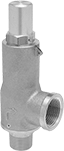
- For Use With: Argon, Carbon Dioxide, Helium, Hydrogen, Methane, Nitrogen, Oxygen
- Specifications Met: ASME BPVC.VIII
- Temperature Range: -320° to 150° F
These valves meet ASME Code Section VIII for use with cryogenic pressure vessels. Rated for use with argon, carbon dioxide, helium, hydrogen, methane, nitrogen, and oxygen, they are cleaned and bagged for oxygen service and other high-purity applications. All spring fully open at the set pressure and remain open until the system pressure is restored below the set pressure. Attach a drain line to the threaded relief port for remote discharge.
![]() For technical drawings and 3-D models, click on a part number.
For technical drawings and 3-D models, click on a part number.
Fast-Acting Pressure-Relief Valves for Cryogenic Liquids
- For Use With: Liquid Argon, Liquid Nitrogen, Liquid Oxygen
- Temperature Range: -320° to 350° F
Cleaned and bagged for oxygen service and other high-purity applications, these valves can withstand the extreme cold of liquid argon, liquid nitrogen, and liquid oxygen. They spring fully open at the set pressure and remain open until the system pressure is restored below the set pressure. All have a vented relief port to exhaust discharge directly.
![]() For technical drawings and 3-D models, click on a part number.
For technical drawings and 3-D models, click on a part number.
High-Accuracy Panel-Mount Vacuum-Regulating Valves for Air and Inert Gas
- For Use With: Air, Argon, Nitrogen
- Temperature Range: -40° to 165° F
For precise control over your vacuum level, these valves have ±0.1% accuracy. They throttle a high vacuum source to maintain a lower vacuum level in your system. Adjust the outlet vacuum level within the range. Valves have threads below the adjustment knob and come with a panel-mount nut. All have a gauge port. They are constant-bleed style, so they continually release small amounts of process gas to improve accuracy and repeatability.
![]() For technical drawings and 3-D models, click on a part number.
For technical drawings and 3-D models, click on a part number.
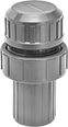
High-Pressure Vacuum-Breaking Valves

- For Use With: Air, Argon, Helium, Krypton, Neon, Oil, Water, Xenon
- Seal Material: Fluoroelastomer Rubber
Rated for 12 times the pressure of standard vacuum-breaking valves, these can handle up to 1,500 psi. Also known as vacuum breakers, they have vents that open when pressure drops to relieve vacuum conditions and prevent backward suction from drawing liquid into upstream piping. Body is 316 stainless steel for excellent corrosion resistance.
Flow coefficient (Cv) is the amount of water (in gallons per minute) at 60° F that will flow through a fully open valve with a difference of 1 psi between the inlet and the outlet.
![]() For technical drawings and 3-D models, click on a part number.
For technical drawings and 3-D models, click on a part number.
Vacuum-Breaking Valves
Also known as vacuum breakers, these valves have vents that open when pressure drops to relieve vacuum conditions and prevent backward suction from drawing liquid into upstream piping.
303 stainless steel valves have the best corrosion resistance.
Straights are often used with steam coils, heat exchangers, and space heaters.
![]() For technical drawings and 3-D models, click on a part number.
For technical drawings and 3-D models, click on a part number.

- For Use With: Air, Argon, Helium, Krypton, Neon, Steam, Water, Xenon
- Seal Material: EPR Rubber
| Inlet Pipe Size | Outlet Pipe Size | Max. Pressure | Temperature Range, °F | End-to-End Lg. | Body Material | Each | |
Brass Body | |||||||
|---|---|---|---|---|---|---|---|
NPT Male Inlet × NPT Female Outlet | |||||||
| 1/2 | 3/8 | 300 psi @ 70° F | -20° to 365° | 1 3/4" | Brass | 0000000 | 0000000 |
| 3/4 | 1/2 | 300 psi @ 70° F | -20° to 365° | 2 1/8" | Brass | 0000000 | 000000 |
| 1 | 3/4 | 300 psi @ 70° F | -20° to 365° | 2 3/8" | Brass | 0000000 | 000000 |
303 Stainless Steel Body | |||||||
NPT Male Inlet × NPT Female Outlet | |||||||
| 1/2 | 3/8 | 300 psi @ 70° F | -20° to 365° | 1 3/4" | 303 Stainless Steel | 0000000 | 000000 |
| 3/4 | 1/2 | 300 psi @ 70° F | -20° to 365° | 2 1/8" | 303 Stainless Steel | 0000000 | 000000 |
| 1 | 3/4 | 300 psi @ 70° F | -20° to 365° | 2 3/8" | 303 Stainless Steel | 0000000 | 000000 |
Vacuum-Breaking Valves for Chemicals
A plastic body withstands pH neutralizing, cleaning, and plating solutions containing sodium hydroxide, methyl ethyl ketone, and other harsh chemicals. Also known as vacuum breakers, these valves have vents that open when pressure drops to relieve vacuum conditions and prevent backward suction from drawing liquid into upstream piping.
![]() For technical drawings and 3-D models, click on a part number.
For technical drawings and 3-D models, click on a part number.
- For Use With: Air, Ammonia, Argon, Beverage, Carbon Dioxide, Chlorinated Water, Diesel Fuel, Drinking Water, Ethylene Glycol, Food, Helium, Hydrochloric Acid, Kerosene, Krypton, Liquid Carbon Dioxide, Methanol, Methyl Ethyl Ketone, Mineral Spirits, Natural Gas, Neon, Nitric Acid, Nitrogen, Oil, Oxygen, Soap Solutions, Sodium Hydroxide, Sodium Hypochlorite, Water, Xenon
- Diaphragm Material: Fluoroelastomer Rubber
- Seal Material: Fluoroelastomer Rubber
| Pipe Size | For Pipe Schedule | Max. Pressure | Min. Opening Pressure, psi | End-to-End Lg. | Color | Temperature Range, °F | Each | |
PVC Plastic Body | ||||||||
|---|---|---|---|---|---|---|---|---|
NPT Female × NPT Female | ||||||||
| 1/2 | 80 | 100 psi @ 75° F | 1 | 4 5/16" | Gray | 40° to 140° | 000000 | 0000000 |
| 3/4 | 80 | 100 psi @ 75° F | 1 | 4 5/8" | Gray | 40° to 140° | 0000000 | 000000 |
| 1 | 80 | 100 psi @ 75° F | 1 | 5 1/8" | Gray | 40° to 140° | 0000000 | 000000 |
CPVC Plastic Body | ||||||||
NPT Female × NPT Female | ||||||||
| 1/2 | 80 | 100 psi @ 75° F | 1 | 4 5/16" | Light Gray | 40° to 180° | 0000000 | 000000 |
| 3/4 | 80 | 100 psi @ 75° F | 1 | 4 5/8" | Light Gray | 40° to 180° | 0000000 | 000000 |
| 1 | 80 | 100 psi @ 75° F | 1 | 5 1/8" | Light Gray | 40° to 180° | 0000000 | 000000 |
- For Use With: Air, Ammonia, Argon, Beverage, Carbon Dioxide, Chlorinated Water, Diesel Fuel, Drinking Water, Ethylene Glycol, Food, Helium, Hydrochloric Acid, Kerosene, Krypton, Liquid Carbon Dioxide, Methanol, Methyl Ethyl Ketone, Mineral Spirits, Natural Gas, Neon, Nitric Acid, Nitrogen, Oil, Oxygen, Soap Solutions, Sodium Hydroxide, Sodium Hypochlorite, Water, Xenon
- Piston Material:
PVC Plastic Body: PVC Plastic
CPVC Plastic Body: CPVC Plastic - Spring Material: Plastic Polymer
- Seal Material: Fluoroelastomer Rubber
| Pipe Size | For Pipe Schedule | Max. Pressure | Min. Opening Pressure, psi | End-to-End Lg. | Color | Temperature Range, °F | Each | |
PVC Plastic Body | ||||||||
|---|---|---|---|---|---|---|---|---|
NPT Female × NPT Female | ||||||||
| 1 1/2 | 80 | 100 psi @ 75° F | 1 | 7 15/16" | Gray | 40° to 140° | 0000000 | 0000000 |
| 2 | 80 | 100 psi @ 75° F | 1 | 8 1/2" | Gray | 40° to 140° | 0000000 | 000000 |
CPVC Plastic Body | ||||||||
NPT Female × NPT Female | ||||||||
| 1 1/2 | 80 | 100 psi @ 75° F | 1 | 7 15/16" | Light Gray | 40° to 180° | 0000000 | 000000 |
| 2 | 80 | 100 psi @ 75° F | 1 | 8 1/2" | Light Gray | 40° to 180° | 0000000 | 000000 |