


Filter by
For Motion
Length


Material
Ball Material
Bearing Material
Dynamic Load Capacity
DFARS Specialty Metals
Export Control Classification Number (ECCN)
REACH
U.S.–Mexico–Canada Agreement (USMCA) Qualifying
RoHS
Root Diameter
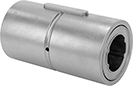
Mounted Linear Bearings for Ball Splines
 |
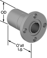
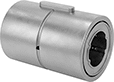
A flange with mounting holes makes it easy to attach a load to these bearings. Create a compact linear and rotary motion system for robots and other applications requiring complex, fast movements, by combining them with ball splines. These bearings move smoothly and precisely even at high speeds along ball splines while grooves on the ball spline transmit rotary power. Clip a retaining ring (not included) into the groove on these bearings to position them in your system.
Steel Bearings
 |  |  |
For 4 Splines |
Groove, mm | ||||||||||||||||||
|---|---|---|---|---|---|---|---|---|---|---|---|---|---|---|---|---|---|---|
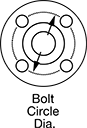
For Spline Dia., mm | For No. of Splines | Overall Lg., mm | Flange OD, mm | Bolt Circle Dia., mm | OD, mm | Dynamic Load Cap., lb. | Static Load Cap., lb. | Max. Dynamic Torque, in·lbf | Max. Static Torque, in·lbf | Max. Temp., ° F | With Retaining Ring Grooves | Wd. | Dia. | No. of Mounting Holes | Each | |||
| 6 | 4 | 25 | 30 | 22 | 14 | 270 | 510 | 13 | 21 | 176 | Yes | 1.25 | 13.7 | 4 | 61145K41 | 0000000 | ||
| 8 | 4 | 25 | 32 | 24 | 16 | 325 | 645 | 18 | 32 | 176 | Yes | 1.25 | 15.6 | 4 | 61145K42 | 000000 | ||
| 10 | 4 | 33 | 42 | 32 | 21 | 610 | 1,100 | 38 | 72 | 176 | Yes | 1.65 | 20.5 | 4 | 61145K43 | 000000 | ||
| 13 | 4 | 36 | 43 | 33 | 24 | 600 | 1,050 | 185 | 346 | 176 | Yes | 1.3 | 22.7 | 4 | 61145K111 | 00000 | ||
| 16 | 4 | 50 | 50 | 40 | 31 | 1,350 | 2,500 | 531 | 973 | 176 | Yes | 1.6 | 29.4 | 4 | 61145K112 | 000000 | ||
| 18.2 | 4 | 60 | 51 | 40 | 32 | 1,750 | 2,500 | 734 | 1,177 | 176 | Yes | 3 | 31.3 | 4 | 61145K46 | 000000 | ||
| 20 | 4 | 63 | 58 | 45 | 35 | 2,000 | 3,650 | 929 | 1,717 | 176 | Yes | 2 | 33 | 4 | 61145K113 | 000000 | ||
| 23 | 4 | 70 | 60 | 47 | 37 | 2,750 | 3,600 | 1,433 | 2,115 | 176 | Yes | 3.5 | 36.1 | 4 | 61145K47 | 000000 | ||
| 25 | 4 | 71 | 65 | 52 | 42 | 2,850 | 5,250 | 1,672 | 3,062 | 176 | Yes | 2.5 | 39.5 | 4 | 61145K114 | 000000 | ||
| 28 | 4 | 80 | 70 | 54 | 45 | 4,150 | 5,200 | 2,557 | 3,646 | 176 | Yes | 4 | 43.9 | 4 | 61145K48 | 000000 | ||
| 30 | 4 | 80 | 75 | 60 | 47 | 4,150 | 5,200 | 2,716 | 3,885 | 176 | Yes | 3 | 44 | 4 | 61145K115 | 000000 | ||
| 37.4 | 4 | 100 | 90 | 72 | 60 | 6,900 | 8,400 | 5,637 | 7,806 | 176 | Yes | 5 | 58.6 | 4 | 61145K49 | 000000 | ||
| 40 | 4 | 100 | 100 | 82 | 64 | 6,900 | 8,400 | 5,964 | 8,266 | 176 | Yes | 4 | 60 | 4 | 61145K116 | 000000 | ||
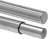
52100 Alloy Steel Splines
|
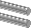 |
Splined on Both Ends |
 |
Splined End × Step-Down End |
 |
4 Splines |
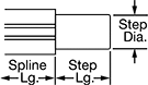 |
Spline | Step, mm | |||||||||
|---|---|---|---|---|---|---|---|---|---|---|
Dia., mm | Lg., mm | No. of | Lg., mm | Root Dia., mm | Dia. | Lg. | Each | |||
Splined on Both Ends | ||||||||||
| 6 | 150 | 4 | 150 | 5.3 | — | — | 61145K61 | 0000000 | ||
| 6 | 200 | 4 | 200 | 5.3 | — | — | 61145K136 | 000000 | ||
| 6 | 300 | 4 | 300 | 5.3 | — | — | 61145K137 | 000000 | ||
| 8 | 150 | 4 | 150 | 7.2 | — | — | 61145K62 | 000000 | ||
| 8 | 200 | 4 | 200 | 7.2 | — | — | 61145K139 | 000000 | ||
| 10 | 200 | 4 | 200 | 9 | — | — | 61145K63 | 000000 | ||
| 10 | 300 | 4 | 300 | 9 | — | — | 61145K144 | 000000 | ||
| 10 | 600 | 4 | 600 | 9 | — | — | 61145K147 | 000000 | ||
| 13 | 200 | 4 | 200 | 11.7 | — | — | 61145K148 | 00000 | ||
| 13 | 500 | 4 | 500 | 11.7 | — | — | 61145K149 | 000000 | ||
| 13 | 700 | 4 | 700 | 11.7 | — | — | 61145K151 | 000000 | ||
| 16 | 200 | 4 | 200 | 14.2 | — | — | 61145K154 | 000000 | ||
| 16 | 700 | 4 | 700 | 14.2 | — | — | 61145K156 | 000000 | ||
| 20 | 200 | 4 | 200 | 17.9 | — | — | 61145K161 | 000000 | ||
| 20 | 2,000 | 4 | 2,000 | 17.9 | — | — | 61145K165 | 00000000 | ||
| 25 | 200 | 4 | 200 | 22.4 | — | — | 61145K166 | 000000 | ||
| 25 | 500 | 4 | 500 | 22.4 | — | — | 61145K167 | 000000 | ||
| 30 | 300 | 4 | 300 | 26.8 | — | — | 61145K172 | 000000 | ||
| 30 | 1,000 | 4 | 1,000 | 26.8 | — | — | 61145K174 | 000000 | ||
| 30 | 2,000 | 4 | 2,000 | 26.8 | — | — | 61145K176 | 00000000 | ||
| 40 | 400 | 4 | 400 | 35.5 | — | — | 61145K177 | 000000 | ||
| 40 | 700 | 4 | 700 | 35.5 | — | — | 61145K178 | 000000 | ||
Splined End × Step-Down End | ||||||||||
| 18.2 | 200 | 4 | 350 | 16.4 | 15 | 150 | 61145K86 | 000000 | ||
| 23 | 200 | 4 | 350 | 20.6 | 20 | 150 | 61145K87 | 000000 | ||
| 28 | 300 | 4 | 450 | 24.8 | 25 | 150 | 61145K88 | 000000 | ||
| 37.4 | 400 | 4 | 550 | 33.1 | 30 | 150 | 61145K89 | 000000 | ||
Linear Bearings for Ball Splines
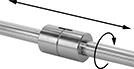 |
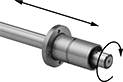
Combine these bearings with a ball spline to create a compact linear and rotary motion system for applications with fast, complex movements, such as robotics. These bearings move smoothly and precisely even at high speeds along ball splines while grooves on the ball spline transmit rotary power. Clip a retaining ring into the groove on these bearings to position them in your system. Use the keyway and included machine key for attaching your load.
Steel Bearings
 | |
For 4 Splines |
Groove, mm | Keyway, mm | ||||||||||||||||||
|---|---|---|---|---|---|---|---|---|---|---|---|---|---|---|---|---|---|---|---|
For Spline Dia., mm | For No. of Splines | Overall Lg., mm | OD, mm | Dynamic Load Cap., lb. | Static Load Cap., lb. | Max. Dynamic Torque, in·lbf | Max. Static Torque, in·lbf | Max. Temp., ° F | With Retaining Ring Grooves | Wd. | Dia. | Includes | Lg. | Wd. | Dp. | Each | |||
| 6 | 4 | 25 | 14 | 270 | 510 | 13 | 21 | 176 | Yes | 1.3 | 13.3 | Machine Key | 10.5 | 2.5 | 1.2 | 61145K31 | 000000 | ||
| 8 | 4 | 25 | 16 | 325 | 645 | 18 | 32 | 176 | Yes | 1.3 | 15.3 | Machine Key | 10.5 | 2.5 | 1.2 | 61145K32 | 00000 | ||
| 10 | 4 | 33 | 21 | 610 | 1,100 | 38 | 72 | 176 | Yes | 1.7 | 20 | Machine Key | 13 | 3 | 1.5 | 61145K33 | 00000 | ||
| 13 | 4 | 36 | 24 | 600 | 1,050 | 185 | 346 | 176 | Yes | 1.3 | 22.7 | Machine Key | 15 | 3 | 1.5 | 61145K12 | 00000 | ||
| 16 | 4 | 50 | 31 | 1,350 | 2,500 | 531 | 973 | 176 | Yes | 1.6 | 29.4 | Machine Key | 17.5 | 3.5 | 2 | 61145K13 | 00000 | ||
| 18.2 | 4 | 60 | 32 | 1,750 | 2,500 | 734 | 1,177 | 176 | Yes | 3.1 | 30.2 | Machine Key | 26 | 4 | 2.5 | 61145K36 | 000000 | ||
| 25 | 4 | 71 | 42 | 2,850 | 5,250 | 1,672 | 3,062 | 176 | Yes | 2.5 | 39.5 | Machine Key | 36 | 4 | 2.5 | 61145K15 | 000000 | ||
| 28 | 4 | 80 | 45 | 4,150 | 5,200 | 2,557 | 3,646 | 176 | Yes | 4.15 | 42.6 | Machine Key | 41 | 7 | 4 | 61145K38 | 000000 | ||
| 30 | 4 | 80 | 47 | 4,150 | 5,200 | 2,716 | 3,885 | 176 | Yes | 3 | 44 | Machine Key | 42 | 4 | 2.5 | 61145K16 | 000000 | ||
| 40 | 4 | 100 | 64 | 6,900 | 8,400 | 5,964 | 8,266 | 176 | Yes | 4 | 60 | Machine Key | 52 | 6 | 3.5 | 61145K17 | 000000 | ||
Stainless Steel Bearings
 | |
For 4 Splines |
Groove, mm | Keyway, mm | ||||||||||||||||||
|---|---|---|---|---|---|---|---|---|---|---|---|---|---|---|---|---|---|---|---|
For Spline Dia., mm | For No. of Splines | Overall Lg., mm | OD, mm | Dynamic Load Cap., lb. | Static Load Cap., lb. | Max. Dynamic Torque, in·lbf | Max. Static Torque, in·lbf | Max. Temp., ° F | With Retaining Ring Grooves | Wd. | Dia. | Includes | Lg. | Wd. | Dp. | Each | |||
| 6 | 4 | 25 | 14 | 270 | 510 | 13 | 21 | 176 | Yes | 0.6 | 13.4 | Machine Key | 10.5 | 2.5 | 1.2 | 61145K23 | 0000000 | ||
| 13 | 4 | 36 | 24 | 600 | 1,050 | 185 | 346 | 176 | Yes | 1.3 | 22.7 | Machine Key | 15 | 3 | 1.5 | 61145K26 | 000000 | ||
Ball Screw/Splines and Bearings
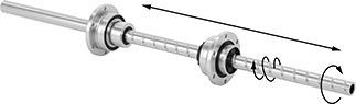 |
From one compact system, transmit linear or rotary motion or both at once (sometimes called spiral motion). Because of these different motions, these ball screw/splines and bearings create efficient, fluid movements in complex automated applications, such as pick-and-place robots.
The ball bearings move smoothly and precisely, even at high speeds. They're powered independently, so you can drive one bearing at a time or both together to coordinate movements.
The ball screw/splines are hardened on the surface, so they stand up to repeated motion. They’re also hollow, so you can run electrical wiring, compressed air tubing, coolants, or lubricant through their center.
Spline | Thread | Ball Screw Bearing | Ball Spline Bearing | |||||||||||||||||
|---|---|---|---|---|---|---|---|---|---|---|---|---|---|---|---|---|---|---|---|---|
Lg., mm | No. of | Lg., mm | Direction, ° F | Thread Direction | ID, mm | Lg., mm | Root Dia., mm | OD, mm | Overall Lg., mm | Dynamic Load Cap., lb. | Static Load Cap., lb. | OD, mm | Overall Lg., mm | Dynamic Load Cap., lb. | Static Load Cap., lb. | Max. Dynamic Torque, in·lbf | Each | |||
1055 Carbon Steel | ||||||||||||||||||||
8 mm Dia. (Tolerance: -0.015 mm to 0 mm) | ||||||||||||||||||||
| 200 | 4 | 180 | 5 to 176 | Right Hand | 3 | 200 | 7.44 | 19 | 28.5 | 240 | 400 | 16 | 25 | 330 | 580 | 17 | 4049N11 | 000000000 | ||
10 mm Dia. (Tolerance: -0.015 mm to 0 mm) | ||||||||||||||||||||
| 300 | 4 | 270 | 5 to 176 | Right Hand | 4 | 300 | 9.27 | 23 | 34.5 | 380 | 600 | 21 | 33 | 600 | 1,100 | 34 | 4049N12 | 00000000 | ||
16 mm Dia. (Tolerance: -0.018 mm to 0 mm) | ||||||||||||||||||||
| 500 | 6 | 360 | 5 to 176 | Right Hand | 11 | 500 | 15.15 | 32 | 40 | 870 | 1,610 | 31 | 50 | 1,590 | 2,830 | 277 | 4049N13 | 00000000 | ||
