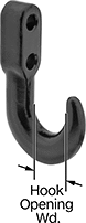
Mount Type Mount Type | Show |
---|
|
Mount Type Mount Type | Hide |
---|
|
System of Measurement System of Measurement |
---|
|
Height Height |
---|
Ball Material Ball Material |
---|
|
Capacity Capacity |
---|
|
Housing Material Housing Material |
---|
|
Diameter Diameter |
---|
|
|
|
Mounting Hole Center-to-Center Mounting HoleCenter-to-Center |
---|
|
|
|
REACH (Registration, Evaluation, Authorization and Restriction of Chemicals) REACH (Registration,Evaluation, Authorization and Restriction of Chemicals) |
---|
|
RoHS (Restriction of Hazardous Substances) RoHS (Restriction ofHazardous Substances) |
---|
|
DFARS (Defense Acquisition Regulations Supplement) DFARS (Defense AcquisitionRegulations Supplement) |
---|
Housing Finish Housing Finish |
---|
|
Maximum Temperature Maximum Temperature |
---|
|
Minimum Temperature Minimum Temperature |
---|
|
About Casters and Wheels
More
Flange-Mount Ball Transfers


Steel balls are durable. 302 stainless steel, 304 stainless steel, and 440 stainless steel balls offer the most corrosion resistance. Acetal balls are abrasion resistant. Nylon balls are nonmarking.
Ball transfers with an angled working orientation can be used to form stock stands.
For technical drawings and 3-D models, click on a part number.
Flange | Mounting Hole | ||||||||||||||
---|---|---|---|---|---|---|---|---|---|---|---|---|---|---|---|
Ball Dia. | Cap., lbs. | Ht. | Dia. | Working Orientation | Housing Color | Lg. | Wd. | Dia. | No.of Mounting Holes | Dia. | Ctr.-to-Ctr. | Temperature Range, °F | Each | ||
Steel Ball | |||||||||||||||
Zinc-Plated Steel Housing | |||||||||||||||
C | 1" | 75 | 1 3/16" | 1 11/16" | Ball Up, Ball Down | __ | 2 3/4" | 2" | __ | 2 | 7/32" | 2 3/16" | Not Rated to 400° | 000000 | 00000 |
C | 1" | 150 | 1 3/16" | 1 1/8" | Ball Up, Ball Down | __ | 2 3/4" | 2" | __ | 2 | 7/32" | 2 3/16" | Not Rated to 400° | 0000000 | 0000 |
F | 1 1/2" | 250 | 1 13/16" | 2 5/8" | Ball Up | __ | 3" | 3" | __ | 4 | 9/32" | 2 15/32" | -22° to 128° | 000000 | 00000 |
Black-Oxide Steel Housing | |||||||||||||||
D | 11/16" | 90 | 1" | 1" | Ball Up, Ball Down, Angle | __ | 2 7/16" | 1 11/16" | __ | 2 | 5/32" | 2" | Not Rated to 400° | 0000000 | 00000 |
D | 1" | 135 | 1 9/32" | 1 1/4" | Ball Up, Ball Down, Angle | __ | 2 7/16" | 1 11/16" | __ | 2 | 5/32" | 2" | Not Rated to 400° | 0000000 | 00000 |
E | 1" | 135 | 1 1/2" | 1 1/4" | Ball Up, Ball Down, Angle | __ | __ | __ | 2 7/16" | 4 | 5/32" | 2 3/16" | Not Rated to 400° | 0000000 | 00000 |
E | 1 1/8" | 180 | 1 19/32" | 1 5/16" | Ball Up, Ball Down, Angle | __ | __ | __ | 2 7/16" | 4 | 5/32" | 2 3/16" | Not Rated to 400° | 0000000 | 00000 |
E | 1 1/4" | 225 | 1 3/4" | 1 15/32" | Ball Up, Ball Down, Angle | __ | __ | __ | 2 7/16" | 4 | 5/32" | 2 3/16" | Not Rated to 400° | 0000000 | 00000 |
Nylon Plastic Housing | |||||||||||||||
A | 1" | 110 | 1 3/8" | 1 23/32" | Ball Up | Black | 2 29/32" | 2 1/16" | __ | 2 | 9/32" | 2 3/8" | 32° to 195° | 0000000 | 00000 |
Acetal Plastic Ball | |||||||||||||||
Nylon Plastic Housing | |||||||||||||||
B | 1" | 20 | 1 5/16" | 1 5/16" | Ball Up | White | 2 1/2" | 1 3/4" | __ | 2 | 7/32" | 1 3/4" | 32° to 195° | 0000000 | 00000 |
Nylon Plastic Ball | |||||||||||||||
Zinc-Plated Steel Housing | |||||||||||||||
C | 1" | 75 | 1 3/16" | 1 5/8" | Ball Up, Ball Down | __ | 2 3/4" | 2" | __ | 2 | 7/32" | 2 3/16" | 32° to 195° | 0000000 | 00000 |
F | 1 1/2" | 250 | 1 13/16" | 2 19/32" | Ball Up, Ball Down, Angle | __ | 3" | 3" | __ | 4 | 9/32" | 2 7/16" | 32° to 195° | 0000000 | 00000 |
Stainless Steel Housing | |||||||||||||||
C | 1" | 75 | 1 3/16" | 1 11/16" | Ball Up, Ball Down, Angle | __ | 2 3/4" | 2" | __ | 2 | 7/32" | 2 3/16" | 32° to 195° | 0000000 | 00000 |
302 Stainless Steel Ball | |||||||||||||||
Nylon Plastic Housing | |||||||||||||||
A | 1" | 110 | 1 3/8" | 1 23/32" | Ball Up | Gray | 2 29/32" | 2 1/16" | __ | 2 | 9/32" | 2 3/8" | 32° to 104° | 0000000 | 00000 |
304 Stainless Steel Ball | |||||||||||||||
Zinc-Plated Steel Housing | |||||||||||||||
C | 1" | 75 | 1 3/16" | 1 5/8" | Ball Up, Ball Down | __ | 2 3/4" | 2" | __ | 2 | 7/32" | 2 3/16" | Not Rated to 400° | 0000000 | 00000 |
Stainless Steel Housing | |||||||||||||||
C | 1" | 125 | 1 3/16" | 1 5/8" | Ball Up, Ball Down | __ | 2 3/4" | 2" | __ | 2 | 7/32" | 2 3/16" | Not Rated to 400° | 0000000 | 00000 |
440 Stainless Steel Ball | |||||||||||||||
Zinc-Plated Steel Housing | |||||||||||||||
F | 1 1/2" | 250 | 1 13/16" | 2 19/32" | Ball Up, Ball Down, Angle | __ | 3" | 3" | __ | 4 | 9/32" | 2 7/16" | Not Rated to 400° | 0000000 | 00000 |
Stainless Steel Housing | |||||||||||||||
F | 1 1/2" | 250 | 1 13/16" | 2 19/32" | Ball Up, Ball Down, Angle | __ | 3" | 3" | __ | 4 | 9/32" | 2 7/16" | Not Rated to 400° | 0000000 | 00000 |
Washdown Flange-Mount Ball Transfers

This ball transfer has a double-sealed ball to keep out dirt and debris. Side vents expel contaminants.
Stainless steel balls offer the most corrosion resistance. Ball transfers with an angled working orientation can be used to form stock stands.
For technical drawings and 3-D models, click on a part number.
Flange | Mounting Hole | ||||||||||||
---|---|---|---|---|---|---|---|---|---|---|---|---|---|
Ball Dia. | Cap., lbs. | Ht. | Dia. | Working Orientation | Housing Color | Lg. | Wd. | No.of Mounting Holes | Dia. | Ctr.-to-Ctr. | Temperature Range, °F | Each | |
Stainless Steel Ball | |||||||||||||
Nylon Plastic Housing | |||||||||||||
1" | 525 | 1 25/32" | 2" | Ball Up, Ball Down, Angle | Black | 3" | 3" | 4 | 1/4" | 2 9/32" | -22° to 128° | 0000000 | 0000000 |
Heavy Duty Flange-Mount Ball Transfers


Steel balls are durable.
Ball transfers with an angled working orientation can be used to form stock stands.
For technical drawings and 3-D models, click on a part number.
Flange | Mounting Hole | |||||||||||
---|---|---|---|---|---|---|---|---|---|---|---|---|
Ball Dia. | Cap., lbs. | Ht. | Dia. | Working Orientation | Lg. | Wd. | No.of Mounting Holes | Dia. | Ctr.-to-Ctr. | Each | ||
Steel Ball | ||||||||||||
Black-Oxide Steel Housing | ||||||||||||
A | 1/2" | 100 | 7/8" | 1" | Ball Up, Ball Down, Angle | 1 7/8" | 1 1/4" | 2 | 5/32" | 1 3/8" | 0000000 | 000000 |
B | 1" | 500 | 1 5/8" | 1 3/4" | Ball Up, Ball Down, Angle | 2 1/4" | 2 1/4" | 4 | 7/32" | 1 3/4" | 0000000 | 000000 |
B | 1" | 705 | 1 25/32" | 2" | Ball Up, Ball Down, Angle | 3" | 3" | 4 | 9/32" | 2 9/32" | 0000000 | 000000 |
B | 1" | 830 | 1 3/4" | 2" | Ball Up, Ball Down, Angle | 3" | 3" | 4 | 5/16" | 2 9/32" | 0000000 | 000000 |
B | 1 1/2" | 2,200 | 2 15/32" | 2 3/8" | Ball Up, Ball Down, Angle | 3" | 3" | 4 | 9/32" | 2 9/32" | 0000000 | 000000 |
B | 1 1/2" | 2,400 | 2 3/8" | 2 3/8" | Ball Up, Ball Down, Angle | 3" | 3" | 4 | 5/16" | 2 9/32" | 0000000 | 000000 |
Shock-Absorbing Flange-Mount Ball Transfers

A thick rubber mounting cushion underneath these ball transfers absorbs impact and reduces vibration.
Steel balls are durable. 440 stainless steel balls offer the most corrosion resistance.
Ball transfers with an angled working orientation can be used to form stock stands.
For technical drawings and 3-D models, click on a part number.
Flange | Mounting Hole | Pad | ||||||||||||
---|---|---|---|---|---|---|---|---|---|---|---|---|---|---|
Ball Dia. | Cap., lbs. | Ht. | Dia. | Working Orientation | Lg. | Wd. | No.of Mounting Holes | Dia. | Ctr.-to-Ctr. | Thick. | Material | Temperature Range, °F | Each | |
Steel Ball | ||||||||||||||
Zinc-Plated Steel Housing | ||||||||||||||
1 1/2" | 250 | 2 1/16" | 2 19/32" | Ball Up, Ball Down, Angle | 3" | 3" | 4 | 9/32" | 2 7/16" | 1/4" | Neoprene Rubber | __ | 0000000 | 000000 |
440 Stainless Steel Ball | ||||||||||||||
Stainless Steel Housing | ||||||||||||||
1 1/2" | 250 | 2 1/16" | 2 19/32" | Ball Up, Ball Down, Angle | 3" | 3" | 4 | 9/32" | 2 7/16" | 1/4" | Neoprene Rubber | Not Rated to 400° | 0000000 | 00000 |
Recessed Flange-Mount Ball Transfers


Transfers recess into the mounting surface for a low profile.
Steel balls are durable. 420 stainless steel and 440 stainless steel balls offer the most corrosion resistance. Nylon balls are nonmarking.
Ball transfers with an angled working orientation can be used to form stock stands.
For technical drawings and 3-D models, click on a part number.
Flange | Mounting Hole | ||||||||||||||
---|---|---|---|---|---|---|---|---|---|---|---|---|---|---|---|
Ball Dia. | Cap., lbs. | Ht. | Dp. | Dia. | Working Orientation | Lg. | Wd. | Dia. | No.of Mounting Holes | Dia. | Ctr.-to-Ctr. | Temperature Range, °F | Each | ||
Steel Ball | |||||||||||||||
Zinc-Plated Steel Housing | |||||||||||||||
A | 1" | 75 | 3/4" | 1/2" | 1 3/4" | Ball Up, Ball Down, Angle | 2 1/8" | 2 3/4" | __ | 2 | 7/32" | 2 3/16" | __ | 0000000 | 00000 |
B | 3/4" | 20 | 13/32" | 15/32" | 1 3/16" | Ball Up, Ball Down, Angle | __ | __ | 2 13/32" | 2 | 7/32" | 1 3/4" | __ | 0000000 | 0000 |
B | 1" | 55 | 9/16" | 5/8" | 1 1/2" | Ball Up, Ball Down, Angle | __ | __ | 2 7/8" | 2 | 3/16" | 2 3/16" | __ | 0000000 | 00000 |
Black-Oxide Steel Housing | |||||||||||||||
C | 11/16" | 90 | 27/32" | 5/32" | 21/32" | Ball Up, Ball Down, Angle | __ | __ | 1 5/16" | 3 | 1/8" | 31/32" | __ | 0000000 | 00000 |
C | 1" | 135 | 1 1/8" | 1/8" | 59/64" | Ball Up, Ball Down, Angle | __ | __ | 1 23/32" | 3 | 5/32" | 1 9/32" | __ | 0000000 | 00000 |
C | 1 1/8" | 180 | 1 1/4" | 5/32" | 31/32" | Ball Up, Ball Down, Angle | __ | __ | 1 13/16" | 3 | 5/32" | 1 11/32" | __ | 0000000 | 00000 |
C | 1 1/4" | 225 | 1 3/8" | 1/8" | 1 1/16" | Ball Up, Ball Down, Angle | __ | __ | 2" | 3 | 5/32" | 1 15/32" | __ | 0000000 | 00000 |
D | 11/16" | 90 | 27/32" | 5/32" | 21/32" | Ball Up, Ball Down, Angle | 1 15/64" | 31/32" | __ | 4 | 1/8" | 11/16", 31/32" | __ | 0000000 | 00000 |
D | 1" | 135 | 1 1/8" | 1/8" | 59/64" | Ball Up, Ball Down, Angle | 1 3/4" | 1 3/8" | __ | 4 | 5/32" | 1", 1 3/8" | __ | 0000000 | 00000 |
D | 1 1/8" | 180 | 1 1/4" | 5/32" | 31/32" | Ball Up, Ball Down, Angle | 1 3/4" | 1 3/8" | __ | 4 | 5/32" | 1", 1 3/8" | __ | 0000000 | 00000 |
Steel Housing | |||||||||||||||
B | 5/8" | 40 | 3/8" | 3/8" | 31/32" | Ball Up, Ball Down, Angle | __ | __ | 1 11/16" | 2 | 1/8" | 1 1/4" | __ | 0000000 | 0000 |
Nylon Plastic Ball | |||||||||||||||
Zinc-Plated Steel Housing | |||||||||||||||
A | 1" | 75 | 3/4" | 1/2" | 1 3/4" | Ball Up, Ball Down, Angle | 2 1/8" | 2 3/4" | __ | 2 | 7/32" | 2 3/16" | 32° to 195° | 0000000 | 00000 |
440 Stainless Steel Ball | |||||||||||||||
Zinc-Plated Steel Housing | |||||||||||||||
A | 1" | 75 | 3/4" | 1/2" | 1 3/4" | Ball Up, Ball Down, Angle | 2 1/8" | 2 3/4" | __ | 2 | 7/32" | 2 3/16" | Not Rated to 400° | 0000000 | 00000 |
Stainless Steel Housing | |||||||||||||||
A | 1" | 75 | 3/4" | 1/2" | 1 3/4" | Ball Up, Ball Down, Angle | 2 1/8" | 2 3/4" | __ | 2 | 7/32" | 2 3/16" | Not Rated to 400° | 0000000 | 00000 |
420 Stainless Steel Ball | |||||||||||||||
Stainless Steel Housing | |||||||||||||||
B | 3/4" | 20 | 13/32" | 15/32" | 1 3/16" | Ball Up, Ball Down, Angle | __ | __ | 2 13/32" | 2 | 7/32" | 1 3/4" | -22° to 128° | 0000000 | 00000 |
B | 1" | 20 | 9/16" | 5/8" | 1 1/2" | Ball Up, Ball Down, Angle | __ | __ | 2 7/8" | 2 | 3/16" | 2 3/16" | -22° to 128° | 0000000 | 00000 |
Washdown Recessed Flange-Mount Ball Transfers

This ball transfer has a double-sealed ball to keep out dirt and debris and side vents to expel contaminants. It recesses into the mounting surface for a low profile.
Stainless steel balls offer the most corrosion resistance. Ball transfers with an angled working orientation can be used to form stock stands.
For technical drawings and 3-D models, click on a part number.
Flange | Mounting Hole | |||||||||||||
---|---|---|---|---|---|---|---|---|---|---|---|---|---|---|
Ball Dia. | Cap., lbs. | Ht. | Dp. | Dia. | Working Orientation | Housing Color | Lg. | Wd. | No.of Mounting Holes | Dia. | Ctr.-to-Ctr. | Temperature Range, °F | Each | |
Stainless Steel Ball | ||||||||||||||
Nylon Plastic Housing | ||||||||||||||
1" | 525 | 1/2" | 1 1/4" | 2" | Ball Up, Ball Down, Angle | Black | 3" | 3" | 4 | 1/4" | 2 9/32" | -22° to 128° | 0000000 | 0000000 |
Heavy Duty Recessed Flange-Mount Ball Transfers


These ball transfers recess into the mounting surface for a low profile.
Steel balls are durable. Ball transfers with an angled working orientation can be used to form stock stands.
For technical drawings and 3-D models, click on a part number.
Flange | Mounting Hole | ||||||||||||
---|---|---|---|---|---|---|---|---|---|---|---|---|---|
Style | Ball Dia. | Cap., lbs. | Ht. | Dp. | Dia. | Working Orientation | Lg. | Wd. | No.of Mounting Holes | Dia. | Ctr.-to-Ctr. | Each | |
Steel Ball with Top Flange | |||||||||||||
Black-Oxide Steel Housing | |||||||||||||
A | 1/2" | 120 | 5/16" | 5/8" | 15/16" | Ball Up; Ball Down; Angle | 1 7/8" | 1 1/4" | 2 | 5/32" | 1 3/8" | 0000000 | 000000 |
B | 1" | 500 | 15/32" | 1 5/32" | 1 3/4" | Ball Up; Ball Down; Angle | 2 1/4" | 2 1/4" | 4 | 7/32" | 1 3/4" | 0000000 | 000000 |
B | 1" | 705 | 1/2" | 1 1/4" | 2" | Ball Up; Ball Down; Angle | 3" | 3" | 4 | 9/32" | 2 9/32" | 0000000 | 000000 |
B | 1" | 850 | 1/2" | 1 1/4" | 2" | Ball Up; Ball Down; Angle | 3" | 3" | 4 | 5/16" | 2 9/32" | 0000000 | 000000 |
B | 1 1/2" | 2,240 | 1" | 1 3/8" | 2 3/8" | Ball Up; Ball Down; Angle | 3" | 3" | 4 | 5/16" | 2 9/32" | 0000000 | 000000 |
Shock-Absorbing Recessed Flange-Mount Ball Transfers

The ball in these transfers is spring-loaded to absorb impact. They are recessed for a low profile.
Steel balls are durable. 304 stainless steel balls offer the most corrosion resistance.
For technical drawings and 3-D models, click on a part number.
Mounting Hole | |||||||||||||
---|---|---|---|---|---|---|---|---|---|---|---|---|---|
Ball Dia. | Cap., lbs. | Max. Deflection @ Load Cap. | Ht. | Dp. | Dia. | Working Orientation | Flange Dia. | No.of Mounting Holes | Dia. | Ctr.-to-Ctr. | Temperature Range, °F | Each | |
Steel Ball | |||||||||||||
Zinc-Plated Steel Housing | |||||||||||||
1" | 125 | 1/4" @ 65 lbs. | 1/2" | 15/16" | 1 11/16" | Ball Up | 3 1/8" | 3 | 3/16" | 2 3/8" | __ | 0000000 | 000000 |
304 Stainless Steel Ball | |||||||||||||
Stainless Steel Housing | |||||||||||||
1" | 125 | 1/4" @ 65 lbs. | 1/2" | 15/16" | 1 11/16" | Ball Up | 3 1/8" | 3 | 3/16" | 2 3/8" | Not Rated to 400° | 0000000 | 000000 |
Wheel Transfers


Mount these wheel transfers with the wheel up to transfer heavy objects. Wheel transfers have completely sealed ball bearings for easy swiveling and the best protection against dust and debris. Also known as air cargo or conveyor casters.
Toe guard reduces the likelihood of tripping.
Wheel | Flange | ||||||||||
---|---|---|---|---|---|---|---|---|---|---|---|
Dia. | Wd. | Cap., lbs. | Ht. | Working Orientation | Lg. | Wd. | No. of Mounting Holes | For Screw Size | Temperature Range, °F | Each | |
Wheel Transfers | |||||||||||
Nylon Plastic Wheel | |||||||||||
Zinc Yellow-Chromate Plated Steel Housing | |||||||||||
2 1/4" | 1 3/4" | 450 | 3 3/4" | Wheel Up | 4 3/8" | 3 3/16" | 6 | 5/16", 7/16" | 0° to 160° | 0000000 | 000000 |
Wheel Transfers with Toe Guard | |||||||||||
Nylon Plastic Wheel | |||||||||||
Zinc Yellow-Chromate Plated Steel Housing | |||||||||||
2 1/4" | 1 3/4" | 450 | 3 3/4" | Wheel Up | 4 3/8" | 3 3/16" | 6 | 5/16", 7/16" | 0° to 160° | 0000000 | 00000 |
Drawbar Rings


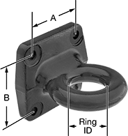
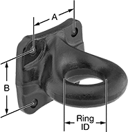
These rings mount to a trailer and connect to the drawbar coupler or tow hook on a vehicle to create a towing connection. Maximum trailer weight is the total weight being towed. Vertical capacity (also known as tongue weight) represents the weight of the load on the drawbar ring.
Note: Capacity is reduced 25% in off-road use.
For technical drawings and 3-D models, click on a part number.
Overall | Ring | Mounting Hole | Mounting Plate | |||||||||||
---|---|---|---|---|---|---|---|---|---|---|---|---|---|---|
Style | For Max. Trailer Wt., lbs. | Vertical Capacity, lbs. | Dp. | Ht. | Material | ID | Thick. | Dia. | Ctr.-to-Ctr. (A) | Ctr.-to-Ctr. (B) | Wd. | Ht. | Each | |
Bolt On | ||||||||||||||
1 | 42,000 | 7,000 | 6 11/16" | 6" | Steel | 2 1/2" | 1 1/4" | 5/8" | 4 1/2" | 4 1/2" | 6" | 6" | 00000000 | 0000000 |
2 | 60,000 | 15,000 | 6 13/16" | 6 3/8" | Steel | 3" | 1 5/8" | 3/4" | 4 1/2" | 4 1/2" | 6 5/8" | 6 3/8" | 00000000 | 000000 |
2 | 100,000 | 20,000 | 6 13/16" | 6 3/8" | Steel | 3" | 1 5/8" | 7/8" | 4 1/2" | 4 1/2" | 6 5/8" | 6 3/8" | 00000000 | 000000 |
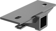
Hitch Receivers


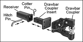
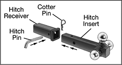
Mount these receivers to a vehicle. Use them with an insert and pin to create a complete hitch for towing. Maximum trailer weight is the total weight being towed. Vertical capacity (also known as tongue weight) represents the weight of the load on the drawbar ring or hitch ball.
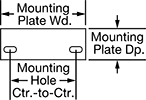
For technical drawings and 3-D models, click on a part number.


Mounting Plate | |||||||||
---|---|---|---|---|---|---|---|---|---|
For Max. Trailer Wt., lbs. | Vertical Capacity, lbs. | Hitch Receiver Size | Material | Color | Mounting Hole Center-to-Center | Wd. | Dp. | Each | |
5,000 | 500 | 2" Square | Powder-Coated Steel | Black | 8 1/2" | 12" | 4 1/2" | 0000000 | 000000 |