


Maximum Continuous Current Maximum Continuous Current |
|---|
|
Switch Type Switch Type |
|---|
|
For Battery Terminal Mounting Location For Battery TerminalMounting Location |
|---|
|
DFARS (Defense Acquisition Regulations Supplement) DFARS (Defense AcquisitionRegulations Supplement) |
|---|
Lever Direction Lever Direction |
|---|
|
Choosing an Electrical Switch
More
Battery Disconnect Switches
Stop battery drain and prevent the theft or unauthorized use of equipment by disconnecting batteries when not in use.
Knob and key actuators can be removed to limit access to the switch.
Use remote-mount switches for easier access. Run a battery cable from the battery to the switch.
Switches with a fused bypass maintain a trickle of current to accessories, such as radios and computers.
Switches with a wing nut accommodate lug terminals.
Knob Actuator for Top Post Mounting
| Max. Continuous Current | For Terminal Polarity | Material | Lg. | Wd. | Ht. | Each | |
| 125 A @ 12 V DC | Negative | Brass | 3 1/2" | 1 1/2" | 1 1/2" | 0000000 | 000000 |
Knob Actuator for Top Post Mounting with Fused Bypass
| Max. Continuous Current | For Terminal Polarity | Material | Lg. | Wd. | Ht. | Each | |
| 125 A @ 12 V DC | Negative | Brass | 3 1/2" | 1 1/2" | 1 1/2" | 0000000 | 000000 |
Key Actuator for Remote Mounting with Water Resistant Cover
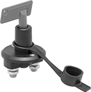
| Max. Continuous Current | Key Removal Position | Material | Ht. | Dia. | No. of Mount. Holes | Mount. Hole Dia. | Includes | Each | |
| 100 A @ 12 V DC | Off | Brass/Copper | 2 1/2" | 2 1/4" | 2 | 0.19" | Two Keys | 0000000 | 000000 |
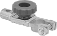
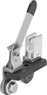
Horizontal Lever Actuator for Top Post Mounting
| Max. Continuous Current | For Terminal Polarity | Material | Lg. | Wd. | Ht. | Each | |
| 250 A @ 12 V DC | Negative | Brass/Copper | 3 3/4" | 3 1/2" | 1 1/2" | 0000000 | 000000 |
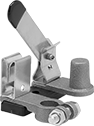
Vertical Lever Actuator for Remote Mounting
| Max. Continuous Current | Material | Lg. | Wd. | Ht. | No. of Mount. Holes | Mount. Hole Dia. | Each | |
| 250 A @ 12 V DC | Brass/Copper | 4" | 3" | 2" | 1 | 0.25" | 0000000 | 000000 |
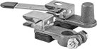
Vertical Lever Actuator for Side Terminal Mounting
| Max. Continuous Current | For Terminal Polarity | Material | Lg. | Wd. | Ht. | Each | |
| 250 A @ 12 V DC | Negative | Brass/Copper | 3 3/4" | 3 1/4" | 1 1/2" | 0000000 | 000000 |
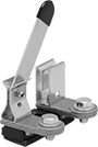
Vertical Level Actuator for Top Post Mounting
| Max. Continuous Current | For Terminal Polarity | Material | Lg. | Wd. | Ht. | Each | |
| 250 A @ 12 V DC | Negative | Brass/Copper | 4" | 3" | 2" | 0000000 | 000000 |
Vertical Lever Actuator for Top Post Mounting with Threaded Stud and Wing Nut
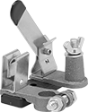
| Max. Continuous Current | For Terminal Polarity | Material | Lg. | Wd. | Ht. | Stud Thread Size | Each | |
| 250 A @ 12 V DC | Negative | Brass/Copper | 4" | 3" | 2 1/4" | 5/16"-18 | 0000000 | 000000 |
Battery Knob Switches
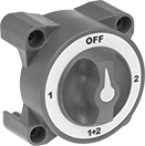
Alternate between two batteries without interrupting power. These switches are often used in marine applications.
![]() For technical drawings and 3-D models, click on a part number.
For technical drawings and 3-D models, click on a part number.
Mounting Holes | |||||||||||||||
|---|---|---|---|---|---|---|---|---|---|---|---|---|---|---|---|
| Actuator Material | No. of Terminals | Max. Voltage | Max. Continuous Current | Terminal Size | For Max. Wire Ga. | No. of | Dia. | Ht. | Wd. | Dp. | Environment | Environmental Rating | Specifications Met | Each | |
With Stud Terminals | |||||||||||||||
For 3 5/8" Cutout Dia. | |||||||||||||||
| Plastic | 3 | 32V DC | 350 A @ 32 V DC | 3/8" | 4/0 | 4 | 1/4" | 3 7/8" | 3 7/8" | 3 1/8" | Washdown | IP66 | UL Listed, UL Marine Listed, CE Marked, ISO 8846, SAE J1171 | 00000000 | 000000 |