


About Linear Bearings
More
About Plain Bearings
More
About Ball and Roller Bearings
More
Light Duty Dry-Running Sleeve Bearings

Use where high loads and speeds are not required.
Note: Dynamic load capacity is the maximum load a bearing can withstand at a given shaft speed. If your application’s load and speed requirements are below the values listed, the bearing will work.
![]() For technical drawings and 3-D models, click on a part number.
For technical drawings and 3-D models, click on a part number.
| For Housing ID | Lg. | Dynamic Radial Load Capacity | Color | Temperature Range, °F | Each | |
Metric Nylon Bearings | ||||||
|---|---|---|---|---|---|---|
For 13mm Shaft Dia. | ||||||
| 16mm | 16mm | 100 lbs. @ 60 rpm | Off-White | -10° to 220° | 00000000 | 000000 |
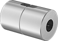
Needle-Roller Bearings
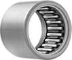
Also known as drawn-cup roller bearings, these are our thinnest roller bearings. The outer ring is drawn out to form a lip that holds the bearing together. Bearings take on the shape of their housing and may be oblong prior to installation.
Open bearings dissipate heat more efficiently than sealed bearings.
![]() For technical drawings and 3-D models, click on a part number.
For technical drawings and 3-D models, click on a part number.
Radial Load Cap., lbs. | ||||||||||||
|---|---|---|---|---|---|---|---|---|---|---|---|---|
| For Shaft Dia. | For Housing ID | Wd. | Ring Material | Dynamic | Static | Max. Speed, rpm | Lubrication | For Shaft Surface Smoothness (Ra), microinch | Temp. Range, °F | Specifications Met | Each | |
Open | ||||||||||||
| 13mm | 19mm | 12mm | Steel | 1,500 | 1,750 | 18,700 | Required | 8 | -20° to 280° | DIN 618, ISO 3245 | 00000000 | 00000 |
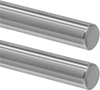
Linear Ball Bearings
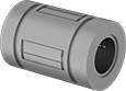
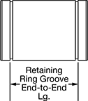
Bearings are for use with round end-supported shafts. To install, slide bearings into a housing (not included). For bearings with retaining ring grooves, secure with two retaining rings (sold individually).
Bearings with end seals keep lubricant in and dust out.
Bearings with stainless steel balls are more corrosion resistant than bearings with steel balls.
Fixed-alignment bearings are for use where shaft misalignment is unlikely.
![]() For technical drawings and 3-D models, click on a part number.
For technical drawings and 3-D models, click on a part number.
Bearings | ||||||||||||
|---|---|---|---|---|---|---|---|---|---|---|---|---|
Load Capacity, lbs. | External Retaining Rings | |||||||||||
| For Shaft Dia., mm | Overall Lg., mm | For Housing ID, mm | Retaining Ring Groove End-to-End Lg., mm | With End Seals | Dynamic | Static | Temperature Range, °F | For Shaft Material | Each | Each | ||
440C Stainless Steel Bearings with Stainless Steel Balls | ||||||||||||
| 13 | 32 | 23.000 - 23.021 | 23 | Yes | 110 | 175 | -4° to 176° | Stainless Steel, Steel | 0000000 | 000000 | 0000000 | 00000 |
Steel Bearings with Steel Balls | ||||||||||||
| 13 | 32 | 23.000 - 23.021 | 23 | Yes | 110 | 175 | -4° to 176° | Stainless Steel, Steel | 00000000 | 00000 | 0000000 | 000 |
Linear Bearings for Spline Shafts
Grooved on the inside, these bearings rotate with your spline shaft as they move loads up and down its length. They have fixed alignment—use them where shaft misalignment is unlikely.
Ball bearings, also known as ball splines, create less friction than plain bearings, making them smooth and precise even at high speeds. However, they don’t produce as much rotational force. Choose them for robotic systems and other automated applications that require complex, fast movements. Bearings with stainless steel balls resist rusting better than those with steel balls.
![]() For technical drawings and 3-D models, click on a part number.
For technical drawings and 3-D models, click on a part number.

| For No. of Splines | For Shaft Dia., mm | Overall Lg., mm | OD, mm | Max. Torque, in.-lbs. | Max. Temperature, °F | Each | |
Fixed Alignment | |||||||
|---|---|---|---|---|---|---|---|
| 4 | 13 | 36 | 24 | 185 | 176° | 00000000 | 000000 |
| For No. of Splines | For Shaft Dia., mm | Overall Lg., mm | OD, mm | Max. Torque, in.-lbs. | Max. Temperature, °F | Each | |
Fixed Alignment | |||||||
|---|---|---|---|---|---|---|---|
| 4 | 13 | 36 | 24 | 185 | 176° | 00000000 | 0000000 |

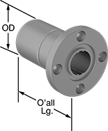
Mounted Linear Bearings for Spline Shafts
Ready to mount on your linear motion spline shaft, these bearings come installed in a housing and have grooves that match up with the splines on your shaft. Because they’re splined, they transfer rotational force as they move loads up and down the shaft’s length. A flanged end makes them best for lifting and lowering loads on vertical shafts. All have fixed alignment—use them where shaft misalignment is unlikely.
Ball bearings, also known as ball splines, create less friction than plain bearings, making them smooth and precise even at high speeds. However, they don’t produce as much rotational force. Choose them for robotic systems and other automated applications that require complex, fast movements.
![]() For technical drawings and 3-D models, click on a part number.
For technical drawings and 3-D models, click on a part number.
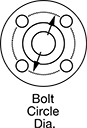
Mounting Holes | |||||||||||
|---|---|---|---|---|---|---|---|---|---|---|---|
| For No. of Splines | For Shaft Dia., mm | Overall Lg., mm | Flange OD, mm | Bolt Circle Dia., mm | OD, mm | Max. Torque, in.-lbs. | Max. Temperature, ° F | No. of | Thread Size | Each | |
Fixed Alignment | |||||||||||
| 4 | 13 | 36 | 43 | 33 | 24 | 185 | 176° | 4 | M4 × 0.7 mm | 000000000 | 000000 |
Quick-Disconnect (QD) Bushings
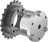

The screw connections on these bushings easily mate to compatible quick-disconnect sprockets and pulleys. Bushings fit quick-disconnect (QD) sprockets and pulleys of the same bushing style. As you tighten the included screws, the bushing grips the shaft and pulls it into the sprocket or pulley.
304 stainless steel bushings resist corrosion from washdowns and humidity, so they’re common in food-processing plants and other frequently-cleaned areas. You can machine the center of these bushings to fit the exact dimensions of your shaft.
![]() For technical drawings and 3-D models, click on a part number.
For technical drawings and 3-D models, click on a part number.
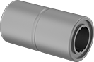
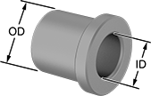
Metric Press-Fit Drill Bushings
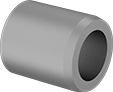
Also known as jig bushings, these metric drill bushings fit inside fixture plate holes to guide drill bits, counterbores, reamers, and other cutting tools. They improve accuracy so that your drilled holes and cuts are consistent from part to part. Known for their versatility, drill bushings are also used as spacers, shims, and machinery bushings. These bushings are made of hardened, ground steel that holds its shape and resists wear, so they last for many cycles without needing to be replaced.
All bushings have a chamfer on the outside that centers the bushing as you place it into the hole. Press into place with a manual or hydraulic press. They also have internal chamfers, so it's easier to insert bits, pins, and punches into the bushing. Some bushings have internal chamfers on both ends, so no matter which end of the bushing is inserted into your jig, your bits, pins, and other tooling enter easily. Having an internal chamfer on the bottom of your bushing may cause shavings to get caught and bind as you remove the bit, however.
DIN 179 bushings meet dimensional and material standards that make sure they're compatible with other parts and tools. Although DIN 179 is no longer an active standard, it's still a common reference point for designers.
Don't see the size you need? Additional sizes are available.
![]() For technical drawings and 3-D models, click on a part number.
For technical drawings and 3-D models, click on a part number.
Tolerance | Each | |||||||||||||
|---|---|---|---|---|---|---|---|---|---|---|---|---|---|---|
| OD, mm | Lg., mm | Internal Chamfer | For Drill Bit Size | ID, mm | OD, mm | Lg., mm | Drill Bushing Type | Material | Hardness | Specifications Met | 1-5 | 6-11 | 12-Up | |
13 mm ID | ||||||||||||||
| 22 | 16 | Both Ends | 13 mm | 0.016 to 0.034 | 0.015 to 0.028 | -0.2 to 0.2 | PM | Steel | Rockwell C61 | __ | 000000000 | 000000 | 000000 | 000000 |
| 22 | 16 | One End | 13 mm | 0.016 to 0.034 | 0.015 to 0.028 | -0.2 to 0.2 | PM | Steel | Rockwell C61 | DIN 179 | 000000000 | 00000 | 00000 | 00000 |
| 22 | 28 | Both Ends | 13 mm | 0.016 to 0.034 | 0.015 to 0.028 | -0.2 to 0.2 | PM | Steel | Rockwell C61 | __ | 000000000 | 00000 | 00000 | 00000 |
| 22 | 28 | One End | 13 mm | 0.016 to 0.034 | 0.015 to 0.028 | -0.4 to 0.4 | PM | Steel | Rockwell C61 | __ | 0000000 | 00000 | 00000 | 00000 |
Metric Press-Fit Drill Bushings with Head
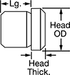


Even under extreme drilling pressure, these metric bushings won't press through your jig plate. A flanged head on the top of the bushing acts as a stop, preventing it from moving as you push down your drill bit, reamer, or other cutting bit. Drill bushings ensure accurate, consistent cuts and drilled holes from one part to the next. They sometimes also work as spacers, shims, and machinery bushings. Made of hardened, ground steel, these bushings hold their shape and resist wear over time. The flanged head protects your jig plate from damage caused by heavy use.
Although it's no longer an active standard, DIN 172 is still a common reference point for making sure parts are compatible with other parts and tools.
These bushings work in both countersunk and standard drill holes. To install, place the bushing inside the hole in your jig. A chamfered edge on the bottom of the bushing helps center the bushing in the hole. Once centered, press the bushing into the hole with a hydraulic or lever press.
![]() For technical drawings and 3-D models, click on a part number.
For technical drawings and 3-D models, click on a part number.
Head | Tolerance | Each | ||||||||||||
|---|---|---|---|---|---|---|---|---|---|---|---|---|---|---|
| OD, mm | Lg., mm | OD, mm | Thick., mm | ID, mm | OD, mm | Lg., mm | Drill Bushing Type | Material | Hardness | Specifications Met | 1-5 | 6-11 | 12-Up | |
13 mm ID | ||||||||||||||
| 22 | 12 | 26 | 4 | 0.016 to 0.034 | 0.015 to 0.028 | -0.2 to 0.2 | H | Steel | Rockwell C61 | DIN 172 | 000000000 | 000000 | 000000 | 000000 |
| 22 | 24 | 26 | 4 | 0.016 to 0.034 | 0.015 to 0.028 | -0.2 to 0.2 | H | Steel | Rockwell C61 | DIN 172 | 000000000 | 00000 | 00000 | 00000 |
| 22 | 32 | 26 | 4 | 0.016 to 0.034 | 0.015 to 0.028 | -0.3 to 0.3 | H | Steel | Rockwell C61 | DIN 172 | 000000000 | 00000 | 00000 | 00000 |