About Linear Bearings
More
Metric Press-Fit Drill Bushings with Head


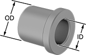
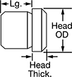
Even under extreme drilling pressure, these metric bushings won't press through your jig plate. They’re ANSI Type H bushings, also known as headed bushings. A flanged head acts as a stop, so these bushings won’t move as you push down your drill bit, reamer, or other cutting bit. Use them even in jigs made of thin or soft materials—the head adds support to protect your jig from damage caused by heavy use. Drill bushings ensure accurate, consistent cuts and drilled holes from one part to the next. They’re also used as spacers, shims, and machinery bushings. Made of hardened, ground steel, these bushings hold their shape and resist wear, so they last for many cycles without needing to be replaced.
These bushings meet DIN 172 dimensional standards. This standard is no longer active, but it’s often used as a reference point for making sure parts are compatible with other parts and tools.
To install, fit the bushing into a hole in your jig. In a standard hole, the head will sit above the jig plate; to mount flush, install in a countersunk hole. A chamfered edge on the bottom of the bushing helps center the bushing in the hole. Once it’s centered, press the bushing into the hole with a hydraulic or lever press.
Head | Tolerance | Each | ||||||||||||||
|---|---|---|---|---|---|---|---|---|---|---|---|---|---|---|---|---|
| OD, mm | Lg., mm | For Drill Bit Size | For Drill Bit Size Decimal Equivalent | OD, mm | Thick., mm | ID, mm | OD, mm | Lg., mm | Drill Bushing Type | Material | Hardness | Specifications Met | 1-5 | 6-11 | 12-Up | |
23 mm ID | ||||||||||||||||
| 35 | 31 | 23 mm | 0.9055" | 39 | 5 | 0.02 to 0.041 | 0.017 to 0.033 | -0.3 to 0.3 | H | Steel | Rockwell C61 | DIN 172 | 000000000 | 000000 | 000000 | 000000 |
Mounted Linear Bearings for Ball Splines

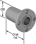
A flange with mounting holes makes it easy to attach a load to these bearings. Create a compact linear and rotary motion system for robots and other applications requiring complex, fast movements, by combining them with ball splines. These bearings move smoothly and precisely even at high speeds along ball splines while grooves on the ball spline transmit rotary power. Clip a retaining ring (not included) into the groove on these bearings to position them in your system.
Splines are alloy steel for high strength and wear resistance. They're hardened only on the outside, so they stand up to repeated motion while keeping their center soft enough to absorb stress from shifting loads. Those with a step-down end have a shoulder near the end to stop gears, sprockets, and bearings.


Groove | ||||||||||||||||
|---|---|---|---|---|---|---|---|---|---|---|---|---|---|---|---|---|
| For Spline Dia., mm | For No. of Splines | Overall Lg., mm | Flange OD, mm | Bolt Circle Dia., mm | OD, mm | Dynamic Load Capacity, lbs. | Static Load Capacity, lbs. | Max. Dynamic Torque, in.-lbs. | Max. Static Torque, in.-lbs. | Max. Temperature, ° F | With Retaining Ring Grooves | Wd., mm | Dia., mm | Number of Mounting Holes | Each | |
| 23 | 4 | 70 | 60 | 47 | 37 | 2,750 | 3,600 | 1,433 | 2,115 | 176° | Yes | 3.5 | 36.1 | 4 | 00000000 | 0000000 |


Step | |||||||||
|---|---|---|---|---|---|---|---|---|---|
| Dia., mm | No. of Splines | Lg., mm | Spline Lg., mm | Root Dia., mm | Dia., mm | Lg., mm | Material | Each | |
Splined End × Step-Down End | |||||||||
| 23 | 4 | 350 | 200 | 20.6 | 20 | 150 | 52100 Alloy Steel | 00000000 | 0000000 |


