


About Plain Bearings
More
About Shaft Collars
Shaft collars are useful for holding and positioning components on a shaft. They can also serve as mechanical stops and stroke limiters.
More
Light Duty Dry-Running Sleeve Bearings

Use where high loads and speeds are not required.
Note: Dynamic load capacity is the maximum load a bearing can withstand at a given shaft speed. If your application’s load and speed requirements are below the values listed, the bearing will work.
![]() For technical drawings and 3-D models, click on a part number.
For technical drawings and 3-D models, click on a part number.
Oil-Embedded Thrust Bearings
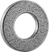
Startup friction causes these porous bronze bearings to release a thin layer of oil on the bearing’s surface. They are also known as Oilite® bearings.
Note: Dynamic load capacity is the maximum load a bearing can withstand at a given shaft speed. If your application’s load and speed requirements are below the values listed, the bearing will work.
![]() For technical drawings and 3-D models, click on a part number.
For technical drawings and 3-D models, click on a part number.
Ultra-Low-Friction Oil-Embedded Thrust Bearings
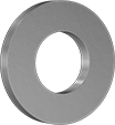
For applications with frequent starts and stops, the oil in these bearings contains particles of slippery PTFE that lubricate the bearing during startup.
Note: Dynamic load capacity is the maximum load a bearing can withstand at a given shaft speed. If your application’s load and speed requirements are below the values listed, the bearing will work.
![]() For technical drawings and 3-D models, click on a part number.
For technical drawings and 3-D models, click on a part number.
Food Industry Oil-Embedded Thrust Bearings
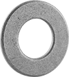
The oil in these bearings is suitable for incidental contact with food. Startup friction causes them to release a thin layer of oil on the bearing’s surface.
Note: Dynamic load capacity is the maximum load a bearing can withstand at a given shaft speed. If your application’s load and speed requirements are below the values listed, the bearing will work.
![]() For technical drawings and 3-D models, click on a part number.
For technical drawings and 3-D models, click on a part number.
High-Load Food Industry Oil-Embedded Thrust Bearings
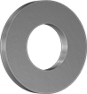
Made of 863 iron-copper and embedded with NSF registered H1 oil, these bearings can tackle high-load applications in food plants, such as bottling and filling lines. Startup friction causes these bearings to release a thin layer of oil onto their surface. The oil is safe for incidental contact with food. Also known as Super Oilite® bearings, these bearings have high iron content, so they’re strong and hold up to shock loads.
![]() For technical drawings and 3-D models, click on a part number.
For technical drawings and 3-D models, click on a part number.
| OD | Thickness | Dynamic Thrust Load Capacity | Lubrication | Lubricant | Temperature Range, °F | Each | |
863 Iron-Copper Bearings | |||||||
|---|---|---|---|---|---|---|---|
For 24mm Shaft Dia. | |||||||
| 48mm | 3mm | 2,450 lbs. @ 60 rpm | Lubricated | SAE 20 Oil | -75° to 300° | 00000000 | 000000 |
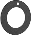
Light Duty Dry-Running Thrust Bearings

Use where high loads and speeds are not required.
Thermoplastic bearings are fiber reinforced and lubricant infused for good wear resistance and low friction with light and medium loads.
Note: Dynamic load capacity is the maximum load a bearing can withstand at a given shaft speed. If your application’s load and speed requirements are below the values listed, the bearing will work.
![]() For technical drawings and 3-D models, click on a part number.
For technical drawings and 3-D models, click on a part number.
| OD | Thick. | Dynamic Thrust Load Capacity | Color | Temperature Range, °F | Each | |
Thermoplastic Blend Bearings | ||||||
|---|---|---|---|---|---|---|
For 28 mm Shaft Dia. | ||||||
| 48mm | 1.5mm | 195 lbs. @ 30 rpm | Gray | -40° to 260° | 0000000 | 00000 |
High-Load Dry-Running Thrust Bearings
A steel backing adds strength to these slippery PTFE bearings.
Note: Dynamic load capacity is the maximum load a bearing can withstand at a given shaft speed. If your application’s load and speed requirements are below the values listed, the bearing will work.
![]() For technical drawings and 3-D models, click on a part number.
For technical drawings and 3-D models, click on a part number.
| OD, mm | Thick., mm | Dynamic Thrust Load Capacity | Temperature Range, °F | Each | |
Steel-Backed PTFE Plastic Bearings | |||||
|---|---|---|---|---|---|
For 28 mm Shaft Dia. | |||||
| 48 | 1.5 | 6,200 lbs. @ 30 rpm | -320° to 530° | 0000000 | 000000 |
Self-Centering Screw-Clamp Bushings
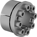

A mounting flange prevents movement during tightening, so it's easy to center these bushings in your sprocket. They are also good for shock loads. When you tighten the included screws, the bushing's inner sleeve contracts onto the shaft and the outer sleeve expands to hold your sprocket, pulley, or gear. They can be mounted on shafts with or without keyways.
![]() For technical drawings and 3-D models, click on a part number.
For technical drawings and 3-D models, click on a part number.
| For Shaft Dia. | OD | Overall Wd. | Max. Torque, in.-lbs. | Fastener Tightening Torque, in.-lbs. | Material | Includes | Each | |
| 30mm | 48mm | 33mm | 4,500 | 90 | Steel | Clamping Screws | 0000000 | 000000 |
Metric Press-Fit Drill Bushings
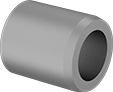
Also known as jig bushings, these metric drill bushings fit inside fixture plate holes to guide drill bits, counterbores, reamers, and other cutting tools. They improve accuracy so that your drilled holes and cuts are consistent from part to part. Known for their versatility, drill bushings are also used as spacers, shims, and machinery bushings. These bushings are made of hardened, ground steel that holds its shape and resists wear, so they last for many cycles without needing to be replaced.
All bushings have a chamfer on the outside that centers the bushing as you place it into the hole. Press into place with a manual or hydraulic press. They also have internal chamfers, so it's easier to insert bits, pins, and punches into the bushing. Some bushings have internal chamfers on both ends, so no matter which end of the bushing is inserted into your jig, your bits, pins, and other tooling enter easily. Having an internal chamfer on the bottom of your bushing may cause shavings to get caught and bind as you remove the bit, however.
DIN 179 bushings meet dimensional and material standards that make sure they're compatible with other parts and tools. Although DIN 179 is no longer an active standard, it's still a common reference point for designers.
Don't see the size you need? Additional sizes are available.
![]() For technical drawings and 3-D models, click on a part number.
For technical drawings and 3-D models, click on a part number.
Tolerance | Each | |||||||||||||
|---|---|---|---|---|---|---|---|---|---|---|---|---|---|---|
| OD, mm | Lg., mm | Internal Chamfer | For Drill Bit Size | ID, mm | OD, mm | Lg., mm | Drill Bushing Type | Material | Hardness | Specifications Met | 1-5 | 6-11 | 12-Up | |
30 mm ID | ||||||||||||||
| 48 | 25 | One End | 30 mm | 0.007 to 0.02 | 0.043 to 0.059 | -0.35 to 0.35 | PM | Steel | Rockwell C61 | __ | 000000000 | 000000 | 000000 | 000000 |
| 48 | 56 | One End | 30 mm | 0.007 to 0.02 | 0.043 to 0.059 | -0.35 to 0.35 | PM | Steel | Rockwell C61 | __ | 000000000 | 00000 | 00000 | 00000 |
32 mm ID | ||||||||||||||
| 48 | 25 | Both Ends | 32 mm | 0.025 to 0.05 | 0.017 to 0.033 | -0.2 to 0.2 | PM | Steel | Rockwell C61 | __ | 000000000 | 00000 | 00000 | 00000 |
| 48 | 25 | One End | 32 mm | 0.025 to 0.05 | 0.017 to 0.033 | -0.2 to 0.2 | PM | Steel | Rockwell C61 | DIN 179 | 000000000 | 00000 | 00000 | 00000 |
32.5 mm ID | ||||||||||||||
| 48 | 25 | One End | 32.5 mm | 0.025 to 0.05 | 0.017 to 0.033 | -0.2 to 0.2 | PM | Steel | Rockwell C61 | DIN 179 | 000000000 | 00000 | 00000 | 00000 |
34 mm ID | ||||||||||||||
| 48 | 25 | Both Ends | 34 mm | 0.025 to 0.05 | 0.017 to 0.033 | -0.2 to 0.2 | PM | Steel | Rockwell C61 | __ | 000000000 | 00000 | 00000 | 00000 |
Metric Press-Fit Drill Bushings with Head
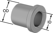
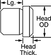


Even under extreme drilling pressure, these metric bushings won't press through your jig plate. A flanged head on the top of the bushing acts as a stop, preventing it from moving as you push down your drill bit, reamer, or other cutting bit. Drill bushings ensure accurate, consistent cuts and drilled holes from one part to the next. They sometimes also work as spacers, shims, and machinery bushings. Made of hardened, ground steel, these bushings hold their shape and resist wear over time. The flanged head protects your jig plate from damage caused by heavy use.
Although it's no longer an active standard, DIN 172 is still a common reference point for making sure parts are compatible with other parts and tools.
These bushings work in both countersunk and standard drill holes. To install, place the bushing inside the hole in your jig. A chamfered edge on the bottom of the bushing helps center the bushing in the hole. Once centered, press the bushing into the hole with a hydraulic or lever press.
![]() For technical drawings and 3-D models, click on a part number.
For technical drawings and 3-D models, click on a part number.
Head | Tolerance | Each | ||||||||||||
|---|---|---|---|---|---|---|---|---|---|---|---|---|---|---|
| OD, mm | Lg., mm | OD, mm | Thick., mm | ID, mm | OD, mm | Lg., mm | Drill Bushing Type | Material | Hardness | Specifications Met | 1-5 | 6-11 | 12-Up | |
30.5 mm ID | ||||||||||||||
| 48 | 20 | 52 | 5 | 0.025 to 0.05 | 0.017 to 0.033 | -0.2 to 0.2 | H | Steel | Rockwell C61 | DIN 172 | 000000000 | 000000 | 000000 | 000000 |
| 48 | 40 | 52 | 5 | 0.025 to 0.05 | 0.017 to 0.033 | -0.3 to 0.3 | H | Steel | Rockwell C61 | DIN 172 | 000000000 | 00000 | 00000 | 00000 |
| 48 | 51 | 52 | 5 | 0.025 to 0.05 | 0.017 to 0.033 | -0.3 to 0.3 | H | Steel | Rockwell C61 | DIN 172 | 000000000 | 000000 | 000000 | 00000 |
31 mm ID | ||||||||||||||
| 48 | 20 | 52 | 5 | 0.025 to 0.05 | 0.017 to 0.033 | -0.2 to 0.2 | H | Steel | Rockwell C61 | DIN 172 | 000000000 | 00000 | 00000 | 00000 |
| 48 | 40 | 52 | 5 | 0.025 to 0.05 | 0.017 to 0.033 | -0.3 to 0.3 | H | Steel | Rockwell C61 | DIN 172 | 000000000 | 00000 | 00000 | 00000 |
| 48 | 51 | 52 | 5 | 0.025 to 0.05 | 0.017 to 0.033 | -0.3 to 0.3 | H | Steel | Rockwell C61 | DIN 172 | 000000000 | 000000 | 000000 | 00000 |
31.5 mm ID | ||||||||||||||
| 48 | 20 | 52 | 5 | 0.025 to 0.05 | 0.017 to 0.033 | -0.2 to 0.2 | H | Steel | Rockwell C61 | DIN 172 | 000000000 | 00000 | 00000 | 00000 |
| 48 | 40 | 52 | 5 | 0.025 to 0.05 | 0.017 to 0.033 | -0.3 to 0.3 | H | Steel | Rockwell C61 | DIN 172 | 000000000 | 00000 | 00000 | 00000 |
| 48 | 51 | 52 | 5 | 0.025 to 0.05 | 0.017 to 0.033 | -0.3 to 0.3 | H | Steel | Rockwell C61 | DIN 172 | 000000000 | 000000 | 000000 | 00000 |
32 mm ID | ||||||||||||||
| 48 | 20 | 52 | 5 | 0.025 to 0.05 | 0.017 to 0.033 | -0.2 to 0.2 | H | Steel | Rockwell C61 | DIN 172 | 000000000 | 00000 | 00000 | 00000 |
| 48 | 40 | 52 | 5 | 0.025 to 0.05 | 0.017 to 0.033 | -0.3 to 0.3 | H | Steel | Rockwell C61 | DIN 172 | 000000000 | 00000 | 00000 | 00000 |
| 48 | 51 | 52 | 5 | 0.025 to 0.05 | 0.017 to 0.033 | -0.3 to 0.3 | H | Steel | Rockwell C61 | DIN 172 | 000000000 | 000000 | 000000 | 00000 |
32.5 mm ID | ||||||||||||||
| 48 | 20 | 52 | 5 | 0.025 to 0.05 | 0.017 to 0.033 | -0.2 to 0.2 | H | Steel | Rockwell C61 | DIN 172 | 000000000 | 00000 | 00000 | 00000 |
| 48 | 40 | 52 | 5 | 0.025 to 0.05 | 0.017 to 0.033 | -0.3 to 0.3 | H | Steel | Rockwell C61 | DIN 172 | 000000000 | 00000 | 00000 | 00000 |
| 48 | 51 | 52 | 5 | 0.025 to 0.05 | 0.017 to 0.033 | -0.3 to 0.3 | H | Steel | Rockwell C61 | DIN 172 | 000000000 | 000000 | 000000 | 00000 |
33 mm ID | ||||||||||||||
| 48 | 20 | 52 | 5 | 0.025 to 0.05 | 0.017 to 0.033 | -0.2 to 0.2 | H | Steel | Rockwell C61 | DIN 172 | 000000000 | 00000 | 00000 | 00000 |
| 48 | 40 | 52 | 5 | 0.025 to 0.05 | 0.017 to 0.033 | -0.3 to 0.3 | H | Steel | Rockwell C61 | DIN 172 | 000000000 | 00000 | 00000 | 00000 |
| 48 | 51 | 52 | 5 | 0.025 to 0.05 | 0.017 to 0.033 | -0.3 to 0.3 | H | Steel | Rockwell C61 | DIN 172 | 000000000 | 000000 | 000000 | 00000 |
33.5 mm ID | ||||||||||||||
| 48 | 20 | 52 | 5 | 0.025 to 0.05 | 0.017 to 0.033 | -0.2 to 0.2 | H | Steel | Rockwell C61 | DIN 172 | 000000000 | 00000 | 00000 | 00000 |
| 48 | 40 | 52 | 5 | 0.025 to 0.05 | 0.017 to 0.033 | -0.3 to 0.3 | H | Steel | Rockwell C61 | DIN 172 | 000000000 | 00000 | 00000 | 00000 |
| 48 | 51 | 52 | 5 | 0.025 to 0.05 | 0.017 to 0.033 | -0.3 to 0.3 | H | Steel | Rockwell C61 | DIN 172 | 000000000 | 000000 | 000000 | 00000 |
34 mm ID | ||||||||||||||
| 48 | 20 | 52 | 5 | 0.025 to 0.05 | 0.017 to 0.033 | -0.2 to 0.2 | H | Steel | Rockwell C61 | DIN 172 | 000000000 | 00000 | 00000 | 00000 |
| 48 | 40 | 52 | 5 | 0.025 to 0.05 | 0.017 to 0.033 | -0.3 to 0.3 | H | Steel | Rockwell C61 | DIN 172 | 000000000 | 00000 | 00000 | 00000 |
| 48 | 51 | 52 | 5 | 0.025 to 0.05 | 0.017 to 0.033 | -0.3 to 0.3 | H | Steel | Rockwell C61 | DIN 172 | 000000000 | 000000 | 000000 | 00000 |
34.5 mm ID | ||||||||||||||
| 48 | 20 | 52 | 5 | 0.025 to 0.05 | 0.017 to 0.033 | -0.2 to 0.2 | H | Steel | Rockwell C61 | DIN 172 | 000000000 | 00000 | 00000 | 00000 |
| 48 | 40 | 52 | 5 | 0.025 to 0.05 | 0.017 to 0.033 | -0.3 to 0.3 | H | Steel | Rockwell C61 | DIN 172 | 000000000 | 00000 | 00000 | 00000 |
| 48 | 51 | 52 | 5 | 0.025 to 0.05 | 0.017 to 0.033 | -0.3 to 0.3 | H | Steel | Rockwell C61 | DIN 172 | 000000000 | 000000 | 000000 | 00000 |
35 mm ID | ||||||||||||||
| 48 | 20 | 52 | 5 | 0.025 to 0.05 | 0.017 to 0.033 | -0.2 to 0.2 | H | Steel | Rockwell C61 | DIN 172 | 000000000 | 00000 | 00000 | 00000 |
| 48 | 40 | 52 | 5 | 0.025 to 0.05 | 0.017 to 0.033 | -0.3 to 0.3 | H | Steel | Rockwell C61 | DIN 172 | 000000000 | 00000 | 00000 | 00000 |
| 48 | 51 | 52 | 5 | 0.025 to 0.05 | 0.017 to 0.033 | -0.3 to 0.3 | H | Steel | Rockwell C61 | DIN 172 | 000000000 | 000000 | 000000 | 00000 |
Bearing Retaining Locknuts
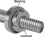
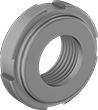
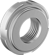
With a nylon insert that grips your threaded shaft or spindle without damaging its threads, these locknuts—also called shaft nuts—hold bearings, bushings, gears, and pulleys prone to vibration tightly in place. They come as one piece, so you can easily clamp them onto your shaft or spindle. But, since they aren’t made entirely of metal, they don’t stand up to heat as well as all-metal locknuts. Slots in their sides mean you can tighten and loosen them with a spanner wrench or spanner socket. Their face is also chamfered to help keep the size and weight of your assembly at a minimum. All meet international standards for bearing locknut dimensions.
When choosing your thread spacing, consider the precision of your application. The finer the threads, the more control you have when making adjustments.
All carbon steel locknuts are strong and resist wear, though they don’t stand up to corrosion as well as stainless steel locknuts. 303 stainless steel locknuts resist corrosion better than steel locknuts but aren’t as strong. They withstand washdowns and chemicals.
![]() For technical drawings and 3-D models, click on a part number.
For technical drawings and 3-D models, click on a part number.
Washdown Clamping Shaft Collars

Suitable for use in washdown applications, these plastic collars also offer good chemical resistance. They clamp evenly around the shaft to create a strong, mar-free hold. To use, slide onto your shaft and tighten the clamping screw to secure.
Acetal collars have a naturally slippery surface and resist swelling when exposed to moisture.
![]() For technical drawings and 3-D models, click on a part number.
For technical drawings and 3-D models, click on a part number.
Clamping Screw | White Acetal Plastic | |||||
|---|---|---|---|---|---|---|
| For Shaft Dia., mm | OD, mm | Wd., mm | Type | No. Included | Each | |
| 28 | 48 | 15 | Socket Head Screw | 1 | 00000000 | 000000 |