


Matching Flow Diagrams to Replace an Air Directional Control Valve
More
Choosing an Air Directional Control Valve
More
About Gradual On/Off Valves
More
About On/Off Valves
More
Air-Operated Air On/Off Valves
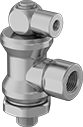
Also known as blocking valves, these valves are activated by an air signal to turn equipment on and off. They allow airflow when an air signal is applied to the air pilot. When the air supply is removed, the valve closes, trapping air in the system.
Valves with push-to-connect ports are for use with plastic or soft metal tubing. Insert tubing into the port.
Flow coefficient (Cv) is a measurement that indicates how much airflow can pass through a valve. When selecting between valves with the same port size, choose the valve with the higher flow coefficient to ensure it provides enough airflow to operate your system.
Air Pilot | Flow Rate @ 100 psi | Overall | ||||||||||||
|---|---|---|---|---|---|---|---|---|---|---|---|---|---|---|
| Inlet Pipe Size | Outlet Pipe Size | Air Pilot Thread Size | For Air Pilot Tube OD | Thread Type | Flow Coefficient (Cv) | Min. | Max. | Max. Pressure, psi | Temp. Range, °F | Lg. | Wd. | Ht. | Each | |
Brass Body | ||||||||||||||
| 1/8 | 1/8 | 10-32 | 5/32" | UNF | 0.64 | 0 scfm | 15 scfm | 145 | 0° to 160° | 1" | 1" | 2" | 62395K61 | 0000000 |
| 1/4 | 1/4 | 10-32 | 5/32" | UNF | 0.87 | 0 scfm | 20 scfm | 145 | 0° to 160° | 1" | 1" | 2" | 62395K62 | 000000 |
| 3/8 | 3/8 | 10-32 | 5/32" | UNF | 2.06 | 0 scfm | 45 scfm | 145 | 0° to 160° | 1 3/8" | 1 1/8" | 2 3/16" | 62395K63 | 000000 |
Outlet | Flow Rate @ 100 psi | Overall | |||||||||||
|---|---|---|---|---|---|---|---|---|---|---|---|---|---|
| For Inlet Tube OD, mm | Thread Size | Thread Pitch, mm | For Air Pilot Tube OD, mm | Flow Coefficient (Cv) | Min. | Max. | Max. Pressure, psi | Temp. Range, °F | Lg., mm | Wd., mm | Ht., mm | Each | |
Zinc Body | |||||||||||||
| 4 | M5 | 0.8 | 4 | 0.203 | 0 scfm | 7.06 scfm | 145 | 15° to 140° | 24.9 | 11 | 39 | 62395K51 | 000000 |
Air Pilot | Flow Rate @ 100 psi | Overall | |||||||||||
|---|---|---|---|---|---|---|---|---|---|---|---|---|---|
| For Inlet Tube OD, mm | Outlet Pipe Size | Thread Size | Thread Pitch, mm | Flow Coefficient (Cv) | Min. | Max. | Max. Pressure, psi | Temp. Range, °F | Lg., mm | Wd., mm | Ht., mm | Each | |
Zinc Body | |||||||||||||
| 6 | 1/8 | M5 | 0.8 | 0.406 | 0 scfm | 14.13 scfm | 145 | 15° to 140° | 32.6 | 13.8 | 48 | 62395K52 | 000000 |
Flow Rate @ 100 psi | Overall | |||||||||||
|---|---|---|---|---|---|---|---|---|---|---|---|---|
| For Inlet Tube OD, mm | Outlet Pipe Size | Air Pilot Pipe Size | Flow Coefficient (Cv) | Min. | Max. | Max. Pressure, psi | Temp. Range, °F | Lg., mm | Wd., mm | Ht., mm | Each | |
Zinc Body | ||||||||||||
| 8 | 1/4 | 1/8 | 0.65 | 0 scfm | 22.6 scfm | 145 | 15° to 140° | 39.6 | 17.8 | 57.3 | 62395K53 | 000000 |
Safety-Lockout Single-Action Air Directional Control Valves
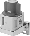
To prevent accidental start-up, these valves can be locked in their off position with a padlock. Also known as 3-way and 3/2 valves, they create one action, such as extending a cylinder. Valves direct airflow from the inlet to your equipment and exhaust return airflow to create motion. They're normally closed to block airflow until actuated. Return actuation is by hand, so they stay actuated and return to their starting position only when you move the actuator again. In the off position, they exhaust air pressure from the system, allowing equipment to reset so the action can be repeated. They help meet OSHA 29 CFR 1910.147 procedures for the control of energy sources that could injure workers.
Flow coefficient (Cv) is a measurement that indicates how much airflow can pass through a valve.
Overall | ||||||||||||||||
|---|---|---|---|---|---|---|---|---|---|---|---|---|---|---|---|---|
| No. of Flow Ports | Inlet Size | Outlet Size | Exhaust Connection Type | Max. Flow Rate, scfm @ 100 psi | Flow Coefficient (Cv) | Pressure Range, psi | Vacuum Rating | Specifications Met | Lg. | Wd. | Ht. | Mounting Fasteners Included | Padlock Included | For Max. Padlock Shackle Dia. | Each | |
Threaded Female Inlet × Threaded Female Outlet | ||||||||||||||||
| 3 | 1/8 NPT | 1/8 NPT | Threaded | 66 | 1.1 | 15-145 | Not Rated | OSHA Compliant 29 CFR 1910.147 | 2 3/8" | 2" | 3 1/2" | No | No | 25/64" | 63015K41 | 000000 |
| 3 | 1/4 NPT | 1/4 NPT | Threaded | 168 | 2.8 | 15-145 | Not Rated | OSHA Compliant 29 CFR 1910.147 | 3 1/2" | 3 3/8" | 5 3/8" | No | No | 25/64" | 63015K44 | 00000 |
| 3 | 3/8 NPT | 3/8 NPT | Threaded | 288 | 4.8 | 15-145 | Not Rated | OSHA Compliant 29 CFR 1910.147 | 3 1/2" | 3 3/8" | 5 3/8" | No | No | 25/64" | 63015K451 | 00000 |
| 3 | 1/2 NPT | 1/2 NPT | Threaded | 379 | 6.3 | 15-145 | Not Rated | OSHA Compliant 29 CFR 1910.147 | 3 1/2" | 3 3/8" | 5 3/8" | No | No | 25/64" | 63015K46 | 00000 |
| 3 | 3/4 NPT | 3/4 NPT | Threaded | 637 | 10.6 | 15-145 | Not Rated | OSHA Compliant 29 CFR 1910.147 | 4 1/2" | 4 1/2" | 6 1/4" | No | No | 25/64" | 63015K47 | 00000 |
| 3 | 1 NPT | 1 NPT | Threaded | 812 | 13.5 | 15-145 | Not Rated | OSHA Compliant 29 CFR 1910.147 | 4 1/2" | 4 1/2" | 6 1/4" | No | No | 25/64" | 63015K48 | 00000 |
Key-Operated Single-Action Air Directional Control Valves
Because they require a key to operate, you can limit who is able to adjust these valves. Also known as 3-way and 3/2 valves, they create one action, such as extending a cylinder. Valves direct airflow from the inlet to your equipment and exhaust return airflow to create motion. They're normally closed to block airflow until actuated. Return actuation is by hand, so they stay actuated and return to their starting position only when you move the actuator again. In the off position, they exhaust air pressure from the system to the atmosphere, allowing equipment to reset so the action can be repeated.
Flow coefficient (Cv) is a measurement that indicates how much airflow can pass through a valve.
Overall | ||||||||||||||
|---|---|---|---|---|---|---|---|---|---|---|---|---|---|---|
| No. of Flow Ports | Inlet Size | Outlet Size | Max. Flow Rate, scfm @ 100 psi | Flow Coefficient (Cv) | Pressure Range, psi | Vacuum Rating, in. of Hg | Lg. | Wd. | Ht. | For Panel Cutout Dia. | Mounting Fasteners Included | No. of Keys Included | Each | |
Threaded Female Inlet × Threaded Female Outlet | ||||||||||||||
| 3 | 1/4 NPT | 1/4 NPT | 33.53 | 1.05 | 0-145 | 29.5 | 1 5/8" | 1 5/8" | 4 1/8" | 1 1/8" | No | 2 | 8444K2 | 000000 |
Key-Operated Two-Speed Two-Action Air Directional Control Valves
Because they require a key to operate, you can limit who is able to adjust these valves. Often used to extend and then retract a cylinder at different speeds, they create two actions and have two exhaust ports, which allows you to control the speed of each action by attaching a flow control valve to each exhaust port. They direct airflow from the inlet to your equipment and exhaust return airflow to create motion. Return actuation is by hand, so they stay actuated and return to their original position only when you move the actuator again. Also known as 4-way and 5/2 valves.
Flow coefficient (Cv) is a measurement that indicates how much airflow can pass through a valve.
Overall | |||||||||||||||
|---|---|---|---|---|---|---|---|---|---|---|---|---|---|---|---|
| No. of Flow Ports | Inlet Size | Outlet Size | Exhaust Connection Type | Max. Flow Rate, scfm @ 100 psi | Flow Coefficient (Cv) | Pressure Range, psi | Vacuum Rating, in. of Hg | Lg. | Wd. | Ht. | For Panel Cutout Dia. | Mounting Fasteners Included | No. of Keys Included | Each | |
Threaded Female Inlet × Threaded Female Outlet | |||||||||||||||
| 5 | 1/8 NPT | 1/8 NPT | Threaded | 11.3 | 0.34 | 14-145 | 26.5 | 7/8" | 1 5/8" | 5 5/8" | 1 1/4" | No | 2 | 8444K34 | 0000000 |
Threaded Isolation On/Off Valves for Chemicals
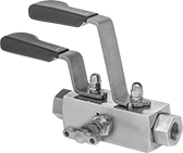
- Valve Type: Ball
- For Use With: Acetone, Air, Ammonia, Argon, Carbon Dioxide, Deionized Water, Diesel Fuel, Ethanol, Fuel Oil, Gasoline, Helium, Isopropyl Alcohol, Kerosene, Krypton, Methanol, Neon, Xenon, Xylene
- Ball Material: 316 Stainless Steel
- Seal Material: PTFE Plastic
- Seat Material: PEEK Plastic
- Specifications Met: ASME B16.34
Attach gauges or sensors to these valves so you can remove them for maintenance and calibration without depressurizing your line. Also known as block and bleed valves, turn the handles to block both upstream and downstream flow, drain the liquid trapped in the valve through the bleed port, and then remove your instrument from the gauge port. Often used in chemical-processing lines, these valves have a PTFE seal and a corrosion-resistant 316 stainless steel body. All are standard port, so they slightly restrict flow.
Flow coefficient (Cv) is the amount of water (in gallons per minute) at 60° F that will flow through a fully open valve with a difference of 1 psi between the inlet and the outlet.
Gauge Port | ||||||||
|---|---|---|---|---|---|---|---|---|
| Pipe Size | Pipe Size | Gender | Thread Type | Flow Coefficient (Cv) | Max. Pressure | Temperature Range, °F | Each | |
316 Stainless Steel Body | ||||||||
NPT Female × NPT Female | ||||||||
| 1/2 | 1/4 | Female | NPT | 6.4 | 10000 psi @ 170° F | -65° to 450° | 2892N12 | 0000000 |
Gradual On/Off Valves with Quick-Clamp Fittings for High Vacuum
Also known as vacuum isolation valves, these block flow so you can install and remove gauges from your system. They can also be used to add or vent gases in high-vacuum systems. Valves gradually open and close with multiple turns of the wheel handle to prevent system damage from suddenly starting and stopping flow. They connect to another quick-clamp (ISO-KF) fitting with a clamp and a ring (sold separately). All have a nonrising stem that stays in the same position whether the valve is open or closed. Body is 304 stainless steel for good corrosion resistance.
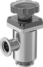
- Valve Type: Gate
- For Use With: Air
- For Tube Material: 304/304L Stainless Steel, 316/316L Stainless Steel
- Seal Material: Viton® Fluoroelastomer Rubber
- Specifications Met: ISO 2861
O'all | |||||||||||
|---|---|---|---|---|---|---|---|---|---|---|---|
| For Tube OD | Flange OD | High Vacuum Connection Type | Max. Vacuum | Temp. Range, °F | Ht. | Lg. | High-Vacuum Flange Size | Sterilize With | Stem Type | Each | |
Quick Clamp | |||||||||||
304 Stainless Steel Body—316 Stainless Steel Gate | |||||||||||
| 1/2" | 1 3/16" | ISO-KF | 10 -8 torr @ 72° F | 0° to 190° | 4 1/8" | 2 1/4" | 10 | Steam (Autoclaving) | Nonrising | 4518K891 | 0000000 |
| 3/4" | 1 3/16" | ISO-KF | 10 -8 torr @ 72° F | 0° to 190° | 4 1/8" | 2 1/4" | 16 | Steam (Autoclaving) | Nonrising | 4518K892 | 000000 |
| 1" | 1 9/16" | ISO-KF | 10 -8 torr @ 72° F | 0° to 190° | 5 5/8" | 3" | 25 | Steam (Autoclaving) | Nonrising | 4518K893 | 000000 |
| 1 1/2" | 2 1/8" | ISO-KF | 10 -8 torr @ 72° F | 0° to 190° | 6 3/8" | 3 7/8" | 40 | Steam (Autoclaving) | Nonrising | 4518K894 | 000000 |
| 2" | 2 15/16" | ISO-KF | 10 -8 torr @ 72° F | 0° to 190° | 8" | 4 1/2" | 50 | Steam (Autoclaving) | Nonrising | 4518K895 | 000000 |
- For Use With: Air
- O-Ring Material: Viton® Fluoroelastomer Rubber
- For Tube Material: 304/304L Stainless Steel, 316/316L Stainless Steel, Aluminum
- Inner Ring Material: 304 Stainless Steel
- Specifications Met: ISO 2861
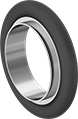
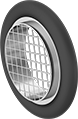
Use these rings with quick-clamp high-vacuum fittings. They consist of a stainless steel inner ring covered by a fluoroelastomer O-ring.
Rings with screen have a stainless steel screen to filter out large particles.
| For Tube OD | For Flange OD | For High-Vacuum Flange Size | Max. Vacuum | Temp. Range, °F | Lg. | Max. Pressure | Each | |
Rings | ||||||||
|---|---|---|---|---|---|---|---|---|
| 1/2" | 1.18" | 10 | 10 -8 torr @ 72° F | 0° to 300° | 5/16" | Not Rated | 4518K813 | 00000 |
| 3/4" | 1.18" | 16 | 10 -8 torr @ 72° F | 0° to 300° | 5/16" | Not Rated | 4518K621 | 0000 |
| 1" | 1.57" | 25 | 10 -8 torr @ 72° F | 0° to 300° | 5/16" | Not Rated | 4518K63 | 00000 |
| 1 1/2" | 2.16" | 40 | 10 -8 torr @ 72° F | 0° to 300° | 5/16" | Not Rated | 4518K64 | 00000 |
| 2" | 2.95" | 50 | 10 -8 torr @ 72° F | 0° to 300° | 5/16" | Not Rated | 4518K65 | 00000 |
Rings with Stainless Steel Screen | ||||||||
| 3/4" | 1.18" | 16 | 10 -8 torr @ 72° F | 0° to 300° | 5/16" | Not Rated | 4518K815 | 00000 |
| 1" | 1.57" | 25 | 10 -8 torr @ 72° F | 0° to 300° | 5/16" | Not Rated | 4518K816 | 00000 |
| 1 1/2" | 2.16" | 40 | 10 -8 torr @ 72° F | 0° to 300° | 5/16" | Not Rated | 4518K817 | 00000 |
| 2" | 2.95" | 50 | 10 -8 torr @ 72° F | 0° to 300° | 5/16" | Not Rated | 4518K818 | 00000 |
Rings with Aluminum Outer Ring | ||||||||
| 3/4" | 1.18" | 16 | 10 -8 torr @ 72° F | 0° to 300° | 5/16" | Not Rated | 4518K911 | 00000 |
| 1" | 1.57" | 25 | 10 -8 torr @ 72° F | 0° to 300° | 5/16" | 100 psi @ 72° F | 4518K67 | 00000 |
| 1 1/2" | 2.16" | 40 | 10 -8 torr @ 72° F | 0° to 300° | 5/16" | 75 psi @ 72° F | 4518K68 | 00000 |
| 2" | 2.95" | 50 | 10 -8 torr @ 72° F | 0° to 300° | 5/16" | 50 psi @ 72° F | 4518K69 | 00000 |