


Clear All
System of Measurement System of Measurement |
|---|
|
Material Material |
|---|
|
For Screw Size For Screw Size | Show |
|---|
For Screw Size For Screw Size | Hide |
|---|
Number of Mounting Slots Number of Mounting Slots |
|---|
|
Mount Type Mount Type |
|---|
|
REACH (Registration, Evaluation, Authorization and Restriction of Chemicals) REACH (Registration,Evaluation, Authorization and Restriction of Chemicals) |
|---|
|
RoHS (Restriction of Hazardous Substances) RoHS (Restriction ofHazardous Substances) |
|---|
|
DFARS (Defense Acquisition Regulations Supplement) DFARS (Defense AcquisitionRegulations Supplement) |
|---|
Appearance Appearance |
|---|
|
Finish Finish |
|---|
|
Mounting Hole Diameter Mounting Hole Diameter |
|---|
|
Number of Mounting Holes Number of Mounting Holes |
|---|
|
Color Color |
|---|
| Black | |
Mounting Hole Style Mounting Hole Style |
|---|
|
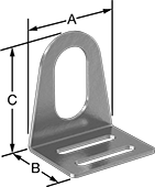
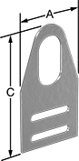
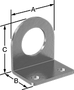
Sensor and Switch Mounting Brackets
1
2
5
Position proximity, photoelectric, and light beam sensors and switches.
Styles 1 and 2 have a sensor/switch slot for mounting adjustments.
![]() For technical drawings and 3-D models, click on a part number.
For technical drawings and 3-D models, click on a part number.
Lg., mm | Mounting | |||||||||||
|---|---|---|---|---|---|---|---|---|---|---|---|---|
| Style | For Sensor/Switch OD, mm | Material | (A) | (B) | (C) | Thick., mm | Sensor/Switch Slot Adjustment Lg., mm | Fasteners Included | Number of Slots | For Screw Size | Each | |
| 1 | 30 | Zinc-Plated Steel | 57 | 45 | 64 | 2.2 | 19 | No | 2 | M7 | 00000000 | 000000 |
| 1 | 30 | 303 Stainless Steel | 57 | 45 | 64 | 2.2 | 19 | No | 2 | M7 | 00000000 | 00000 |
| 1 | 36 | 304 Stainless Steel | 57 | 45 | 64 | 2.2 | 32 | No | 2 | M7 | 000000000 | 00000 |
| 1 | 47 | 304 Stainless Steel | 64 | 51 | 89 | 3.1 | 38 | No | 2 | M7 | 000000000 | 00000 |
| 2 | 30 | 304 Stainless Steel | 57 | __ | 105 | 2.2 | 12 | No | 2 | M7 | 00000000 | 00000 |
| 2 | 47 | 304 Stainless Steel | 63 | __ | 135 | 3.1 | 9 | No | 2 | M7 | 000000000 | 00000 |
| 5 | 30 | 304 Stainless Steel | 51 | 38 | 54 | 3 | __ | No | 2 | M7 | 000000000 | 00000 |
| 5 | 36 | 304 Stainless Steel | 51 | 38 | 54 | 3 | __ | No | 2 | M7 | 000000000 | 00000 |
Impact-Resistant Sensor and Switch Mounting Brackets
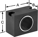
For 30 mm Sensor/Switch OD
The spring-loaded design absorbs impact to protect sensors and switches from damage. Use these brackets to position proximity, photoelectric, and light beam sensors and switches.
![]() For technical drawings and 3-D models, click on a part number.
For technical drawings and 3-D models, click on a part number.
Lg., mm | Mounting | |||||||||||
|---|---|---|---|---|---|---|---|---|---|---|---|---|
| For Sensor/Switch OD, mm | Material | Color | (A) | (B) | (C) | Fasteners Included | Number of Holes | Hole Dia., mm | Hole Style | For Screw Size | Each | |
| 30 | Anodized Aluminum | Black | 64 | 35 | 51 | No | 2 | 7 | Countersunk | M7 | 00000000 | 0000000 |