


System of Measurement System of Measurement |
|---|
|
For Caster Mount Height For Caster Mount Height |
|---|
|
Material Material | Show |
|---|
|
Maximum Torque Maximum Torque |
|---|
|
|
Mounting Location Mounting Location |
|---|
|
Brake Retraction Pedal Location Brake RetractionPedal Location |
|---|
|
Brake Extension Pedal Location Brake ExtensionPedal Location |
|---|
|
DFARS (Defense Acquisition Regulations Supplement) DFARS (Defense AcquisitionRegulations Supplement) |
|---|
For Screw Size For Screw Size |
|---|
REACH (Registration, Evaluation, Authorization and Restriction of Chemicals) REACH (Registration,Evaluation, Authorization and Restriction of Chemicals) |
|---|
|
Shaft Mount Type Shaft Mount Type |
|---|
| Set Screw | |
RoHS (Restriction of Hazardous Substances) RoHS (Restriction ofHazardous Substances) |
|---|
|
Torque Adjustability Torque Adjustability |
|---|
|
Maximum Speed Maximum Speed |
|---|
|


Shaft Coupling Type Shaft Coupling Type |
|---|
|
Torque-Limiting Mechanism Torque-Limiting Mechanism |
|---|
|
Torque-Limiting Flexible Shaft Couplings with Alarm
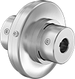
If they exceed maximum torque, these couplings disengage, sound an alarm, and then automatically re-engage once the overtorque condition is eliminated. Torque can be adjusted ±10% of the factory setting. No lubrication is required. Fasten to your shaft by tightening the set screws, which bite into the shaft to hold it.
![]() For technical drawings and 3-D models, click on a part number.
For technical drawings and 3-D models, click on a part number.
Misalignment Capability | ||||||||||||
|---|---|---|---|---|---|---|---|---|---|---|---|---|
| For Shaft Dia. | Max. Speed, rpm | Parallel | Angular | OD | Overall Lg. | Keyway Wd. × Keyway Dp. | Material | Center Material | Torque-Limiting Direction | Choose a Max. Torque, in.-lbs. | Each | |
For Keyed Shafts | ||||||||||||
| 5/8" | 1,800 | 0.031" | 6° | 3 1/2" | 3" | 3/16" × 3/32" | 6061 Aluminum | Steel | Clockwise and Counterclockwise | 0000000 | 000000 | |
| 3/4" | 1,800 | 0.031" | 6° | 3 1/2" | 3" | 3/16" × 3/32" | 6061 Aluminum | Steel | Clockwise and Counterclockwise | 0000000 | 00000 | |
| 7/8" | 1,800 | 0.031" | 6° | 3 1/2" | 3" | 3/16" × 3/32" | 6061 Aluminum | Steel | Clockwise and Counterclockwise | 0000000 | 00000 | |
| 1" | 1,800 | 0.031" | 6° | 3 1/2" | 3" | 1/4" × 1/8" | 6061 Aluminum | Steel | Clockwise and Counterclockwise | 0000000 | 00000 | |
For Round Shafts | ||||||||||||
| 1/2" | 1,800 | 0.031" | 6° | 3 1/2" | 3" | __ | 6061 Aluminum | Steel | Clockwise and Counterclockwise | 0000000 | 00000 | |
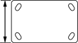
Adjustable-Height Floor Locks
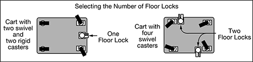
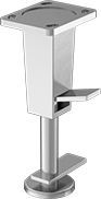
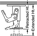
Set these floor locks to the height you need to compensate for uneven and sloped floors. Use them to stabilize carts, trucks, workbenches, and other mobile equipment during loading and unloading. Floor locks bolt to the underside of your equipment and have a spring-loaded base with a nonskid floor pad to keep equipment stationary.
Note: Floor locks are not load rated. They are designed to brake your equipment in place, not lift it off the floor.
![]() For technical drawings and 3-D models, click on a part number.
For technical drawings and 3-D models, click on a part number.
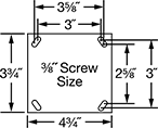
Mounting Plate | Mounting Hole Ctr.-to-Ctr. | |||||||||
|---|---|---|---|---|---|---|---|---|---|---|
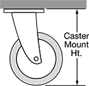
| For Caster Mount Ht. | Ht. Range | Clearance | Lg. | Wd. | Lg. | Wd. | Mounting Fasteners Included | For Screw Size | Each | |
Side Retraction Pedal | ||||||||||
Aluminum | ||||||||||
| 6 1/2"-7 1/2" | 5 1/2"-8" | 2 1/2" | 4 3/4" | 3 3/4" | 3 5/8", 3" | 3", 2 5/8" | No | 3/8" | 0000000 | 0000000 |
| 8"-10 1/2" | 7"-11" | 4" | 4 3/4" | 3 3/4" | 3 5/8", 3" | 3", 2 5/8" | No | 3/8" | 0000000 | 000000 |