Filter by
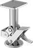
For Caster Mount Height


Height
Brake Retraction Pedal Location
Color
Weight Capacity
System of Measurement
Export Control Classification Number (ECCN)
DFARS Specialty Metals
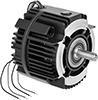
Maximum Torque
Voltage
Material Handling

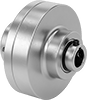
Power Transmission
Fabricating and Machining
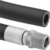
Fluid Handling