


System of Measurement System of Measurement | Show |
|---|
|
Maximum Torque Maximum Torque |
|---|
|
|

For Shaft Type For Shaft Type |
|---|
| Keyed | |

Torque-Limiting Mechanism Torque-Limiting Mechanism |
|---|
|
Torque Adjustability Torque Adjustability |
|---|
|

Torque Limiter Type Torque Limiter Type |
|---|
|

Construction Construction |
|---|
|
Shaft Mount Type Shaft Mount Type |
|---|
| Set Screw | |
Torque-Limiting Direction Torque-Limiting Direction |
|---|
|
Number of Set Screws Included Number of SetScrews Included |
|---|
|
Parallel Misalignment Capability Parallel MisalignmentCapability |
|---|
|
Angular Misalignment Capability Angular MisalignmentCapability |
|---|
|
Number of Teeth Number of Teeth |
|---|
|
Shaft Coupling Type Shaft Coupling Type |
|---|
|
REACH (Registration, Evaluation, Authorization and Restriction of Chemicals) REACH (Registration,Evaluation, Authorization and Restriction of Chemicals) |
|---|
|
RoHS (Restriction of Hazardous Substances) RoHS (Restriction ofHazardous Substances) |
|---|
|
Torque-Limiting Flexible Shaft Couplings
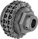
Protect shafts, motors, and gear boxes from damage that’s caused by torque overload from machine jams and emergency stops. If your set torque is exceeded, these couplings will disengage and then automatically re-engage once the torque is back within range. They handle more than five times as much torque as our other torque-limiting flexible shaft couplings. Connect them to your shafts with the included set screws, which bite into the shaft or shaft and key for a secure hold.
Single-spring couplings let you make finer torque adjustments than the double-spring couplings, but can only withstand half as much torque.
Double-spring couplings handle twice as much torque as the single-spring couplings, but are not the best for making precise adjustments at low torques.
Couplings for keyed shafts have keyways that are cut to standard ANSI dimensions, so they’ll fit snugly on ANSI keyed shafts to eliminate slipping during starts and stops.
![]() For technical drawings and 3-D models, click on a part number.
For technical drawings and 3-D models, click on a part number.
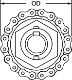
Misalignment Capability | Roller Chain | ||||||||||||
|---|---|---|---|---|---|---|---|---|---|---|---|---|---|
| For Shaft Dia. | Max. Torque, ft.-lbs. | Max. Speed, rpm | Parallel | Angular | OD | Overall Lg. | Keyway Wd. × Keyway Dp. | Hub Material | Torque-Limiting Direction | Standard | Trade Size | Each | |
Single Spring | |||||||||||||
For Keyed Shafts | |||||||||||||
| 12mm × 12mm | 25 | 1,800 | 0.01" | 3° | 2 3/4" | 2 1/4" | 4mm × 2mm 4mm × 2mm | Steel | Clockwise and Counterclockwise | ANSI | 35-2 | 00000000 | 0000000 |
| 12mm × 15mm | 25 | 1,800 | 0.01" | 3° | 2 3/4" | 2 1/4" | 4mm × 2mm 5mm × 2.5mm | Steel | Clockwise and Counterclockwise | ANSI | 35-2 | 00000000 | 000000 |
| 15mm × 15mm | 25 | 1,800 | 0.01" | 3° | 2 3/4" | 2 1/4" | 5mm × 2.5mm 5mm × 2.5mm | Steel | Clockwise and Counterclockwise | ANSI | 35-2 | 00000000 | 000000 |
| 15mm × 20mm | 75 | 1,800 | 0.01" | 3° | 3 11/16" | 2 13/16" | 5mm × 2.5mm 6mm × 3mm | Steel | Clockwise and Counterclockwise | ANSI | 40-2 | 00000000 | 000000 |
| 20mm × 20mm | 75 | 1,800 | 0.01" | 3° | 3 11/16" | 2 13/16" | 6mm × 3mm 6mm × 3mm | Steel | Clockwise and Counterclockwise | ANSI | 40-2 | 00000000 | 000000 |
| 20mm × 25mm | 75 | 1,800 | 0.01" | 3° | 3 11/16" | 2 13/16" | 6mm × 3mm 8mm × 4mm | Steel | Clockwise and Counterclockwise | ANSI | 40-2 | 00000000 | 000000 |
| 25mm × 25mm | 75 | 1,800 | 0.01" | 3° | 3 11/16" | 2 13/16" | 8mm × 4mm 8mm × 4mm | Steel | Clockwise and Counterclockwise | ANSI | 40-2 | 00000000 | 000000 |
Double Spring | |||||||||||||
For Keyed Shafts | |||||||||||||
| 12mm × 12mm | 50 | 1,800 | 0.01" | 3° | 2 3/4" | 2 1/4" | 4mm × 2mm 4mm × 2mm | Steel | Clockwise and Counterclockwise | ANSI | 35-2 | 00000000 | 000000 |
| 12mm × 15mm | 50 | 1,800 | 0.01" | 3° | 2 3/4" | 2 1/4" | 4mm × 2mm 5mm × 2.5mm | Steel | Clockwise and Counterclockwise | ANSI | 35-2 | 00000000 | 000000 |
| 15mm × 15mm | 50 | 1,800 | 0.01" | 3° | 2 3/4" | 2 1/4" | 5mm × 2.5mm 5mm × 2.5mm | Steel | Clockwise and Counterclockwise | ANSI | 35-2 | 00000000 | 000000 |
| 15mm × 20mm | 150 | 1,800 | 0.01" | 3° | 3 11/16" | 2 13/16" | 5mm × 2.5mm 6mm × 3mm | Steel | Clockwise and Counterclockwise | ANSI | 40-2 | 00000000 | 000000 |
| 20mm × 20mm | 150 | 1,800 | 0.01" | 3° | 3 11/16" | 2 13/16" | 6mm × 3mm 6mm × 3mm | Steel | Clockwise and Counterclockwise | ANSI | 40-2 | 00000000 | 000000 |
| 20mm × 25mm | 150 | 1,800 | 0.01" | 3° | 3 11/16" | 2 13/16" | 6mm × 3mm 8mm × 4mm | Steel | Clockwise and Counterclockwise | ANSI | 40-2 | 00000000 | 000000 |
| 25mm × 25mm | 150 | 1,800 | 0.01" | 3° | 3 11/16" | 2 13/16" | 8mm × 4mm 8mm × 4mm | Steel | Clockwise and Counterclockwise | ANSI | 40-2 | 00000000 | 000000 |