Filter by
Valve Type
System of Measurement
Set Pressure
Maximum Inlet Pressure
Airflow Capacity
Inlet Thread Type
Set Pressure Configuration
Maximum Temperature
Maximum Pressure
Thread Type
Inlet Connection
Actuation
REACH
DFARS Specialty Metals
Export Control Classification Number (ECCN)
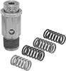
About Pressure-Relief Valves
Choose the correct valve type and pipe size to safely manage the pressure of your system.
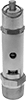
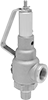
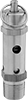
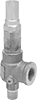
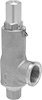
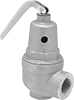
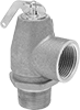
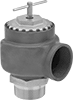
Pressure-Relief Valves
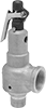
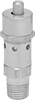
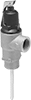
Fast-Acting Pressure-Relief Valves