Filter by
Actuator Style
Switching Current
Switching Voltage
Position Designation
Switch Action
Panel Cutout Diameter
Switch Starting Position
Environment
Mounting Location
Wire Connection
Voltage
Material
Illumination
Export Control Classification Number (ECCN)
DFARS Specialty Metals

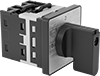
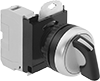
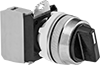
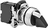
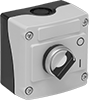
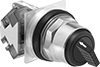
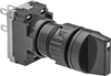
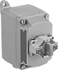
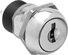
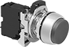
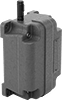
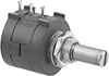
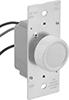
About Electrical Switches
Choose a switch with the right trigger type, number of inputs, and control functions to power your equipment.