


Body Material Body Material | Hide |
|---|
|
Maximum Inlet Pressure Maximum Inlet Pressure |
|---|
|
Valve Function Valve Function |
|---|
|
Maximum Temperature Maximum Temperature |
|---|
|
Inlet Thread Type Inlet Thread Type |
|---|
|
Valve Type Valve Type |
|---|
|
Seal Material Seal Material |
|---|
|
Flow Coefficient (Cv) Flow Coefficient (Cv) |
|---|
|
|
|
Outlet Thread Type Outlet Thread Type |
|---|
|
Set Pressure Set Pressure |
|---|
Diaphragm Material Diaphragm Material |
|---|
|
Inlet Connection Type Inlet Connection Type |
|---|
| Pipe | |
Activation Activation |
|---|
|
Outlet Connection Style Outlet Connection Style |
|---|
 |
| Threaded |
Inlet Connection Style Inlet Connection Style |
|---|
|
| Threaded |
RoHS (Restriction of Hazardous Substances) RoHS (Restriction ofHazardous Substances) |
|---|
|
REACH (Registration, Evaluation, Authorization and Restriction of Chemicals) REACH (Registration,Evaluation, Authorization and Restriction of Chemicals) |
|---|
|
About Pressure-Relief Valves
More
Vibration-Damping Pressure-Regulating Valves for Water, Oil, Air, and Inert Gas
- For Use With: Water, Oil, Air, Inert Gas
- Temperature Range: See Table
A cast iron body absorbs vibration from pressure changes to reduce wear and noise in your pipeline. These valves automatically reduce a high, variable inlet pressure to a lower, stable outlet pressure. Adjust the outlet pressure within the range.
Internal strainers trap debris.
![]() For technical drawings and 3-D models, click on a part number.
For technical drawings and 3-D models, click on a part number.
Inlet | Outlet | ||||||||
|---|---|---|---|---|---|---|---|---|---|
| Pipe Size | Location | Max. Pressure, psi | Pipe Size | Location | Temperature Range | End-to-End Lg. | Choose an Outlet Pressure Range, psi | Each | |
NPT Female | |||||||||
Cast Iron Body—Buna-N Diaphragm and Seal with Internal Strainer | |||||||||
| 1/4 | Side | 200 | 1/4 | Side | 32° to 180° F | 3" | 0000000 | 0000000 | |
| 3/8 | Side | 200 | 3/8 | Side | 32° to 180° F | 3 7/8" | 0000000 | 000000 | |
| 1/2 | Side | 200 | 1/2 | Side | 32° to 180° F | 4 1/2" | 0000000 | 000000 | |
| 3/4 | Side | 200 | 3/4 | Side | 32° to 180° F | 5 1/8" | 0000000 | 000000 | |
| 1 | Side | 200 | 1 | Side | 32° to 180° F | 5 7/8" | 0000000 | 000000 | |
| 1 1/4 | Side | 200 | 1 1/4 | Side | 32° to 180° F | 6 3/4" | 0000000 | 000000 | |
| 1 1/2 | Side | 200 | 1 1/2 | Side | 32° to 180° F | 6 3/4" | 0000000 | 000000 | |
| 2 | Side | 200 | 2 | Side | 32° to 180° F | 9 1/4" | 0000000 | 000000 | |
Cast Iron Body—Fluoroelastomer Diaphragm and 420 Stainless Steel Seal | |||||||||
| 3/8 | Side | 250 | 3/8 | Side | 32° to 300° F | 4 1/4" | 0000000 | 000000 | |
| 1/2 | Side | 250 | 1/2 | Side | 32° to 300° F | 3 5/8" | 0000000 | 000000 | |
| 3/4 | Side | 250 | 3/4 | Side | 32° to 300° F | 3 5/8" | 0000000 | 000000 | |
| 1 | Side | 250 | 1 | Side | 32° to 300° F | 4 1/2" | 0000000 | 000000 | |
| 2 | Side | 250 | 2 | Side | 32° to 300° F | 6 1/2" | 0000000 | 000000 | |
Pressure-Regulating Valves for Steam
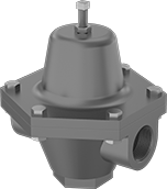
- For Use With: Steam
- Temperature Range: -20° to 400° F
Automatically reduce a high, variable inlet pressure in your steam system to a lower, stable outlet pressure. Adjust the outlet pressure within the range. These valves have a cast iron body that absorbs vibration from pressure changes to reduce wear and noise in your pipeline.
Internal strainers trap debris.
![]() For technical drawings and 3-D models, click on a part number.
For technical drawings and 3-D models, click on a part number.
Valves | ||||||||||
|---|---|---|---|---|---|---|---|---|---|---|
Inlet | Outlet | Repair Kits | ||||||||
| Pipe Size | Location | Max. Pressure, psi | Pipe Size | Location | End-to-End Lg. | Choose an Outlet Pressure Range, psi | Each | Each | ||
NPT Female | ||||||||||
Cast Iron Body—Bronze Diaphragm and 420 Stainless Steel Seal | ||||||||||
| 1/2 | Side | 250 | 1/2 | Side | 3 5/8" | 0000000 | 0000000 | 0000000 | 000000 | |
| 3/4 | Side | 250 | 3/4 | Side | 3 5/8" | 0000000 | 000000 | 0000000 | 00000 | |
| 1 | Side | 250 | 1 | Side | 4 1/2" | 0000000 | 000000 | 0000000 | 000000 | |
| 1 1/4 | Side | 250 | 1 1/4 | Side | 4 1/2" | 0000000 | 000000 | 0000000 | 000000 | |
| 1 1/2 | Side | 250 | 1 1/2 | Side | 6 1/2" | 0000000 | 000000 | 0000000 | 000000 | |
| 2 | Side | 250 | 2 | Side | 6 1/2" | 0000000 | 000000 | 0000000 | 000000 | |
Cast Iron Body—Bronze Diaphragm and PTFE Seal with Internal Strainer | ||||||||||
| 1/4 | Side | 150 | 1/4 | Side | 3" | 0000000 | 000000 | 000000 | 00 | |
| 3/8 | Side | 150 | 3/8 | Side | 3 7/8" | 0000000 | 000000 | 000000 | 00 | |
| 1/2 | Side | 150 | 1/2 | Side | 4 1/2" | 0000000 | 000000 | 0000000 | 000000 | |
| 3/4 | Side | 150 | 3/4 | Side | 5 1/8" | 0000000 | 000000 | 0000000 | 000000 | |
| 1 | Side | 150 | 1 | Side | 5 7/8" | 0000000 | 000000 | 0000000 | 000000 | |
| 1 1/4 | Side | 150 | 1 1/4 | Side | 6 3/4" | 0000000 | 000000 | 0000000 | 000000 | |
| 1 1/2 | Side | 150 | 1 1/2 | Side | 6 3/4" | 0000000 | 000000 | 0000000 | 000000 | |
| 2 | Side | 150 | 2 | Side | 9 1/4" | 0000000 | 000000 | 0000000 | 000000 | |
High-Accuracy Pressure-Regulating Valves for Steam
- For Use With: Steam
- Temperature Range: 40° to 450° F
Control steam line pressure with ±1 psi accuracy. These valves automatically reduce a high, variable inlet pressure to a lower, stable outlet pressure. Adjust the outlet pressure within the range. Valves have a cast iron body that absorbs vibration from pressure changes to reduce wear and noise in your pipeline. They meet ANSI/FCI 70-2 Class IV for tight shut-off (max. leakage rate of 0.01%). Install 1/4 NPT male pipe (not included) between the control valve and your downstream steam line.
Repair kits (sold separately) include replacement seals, diaphragm, spring, and spring assembly.
![]() For technical drawings and 3-D models, click on a part number.
For technical drawings and 3-D models, click on a part number.
Valves | |||||||||
|---|---|---|---|---|---|---|---|---|---|
Inlet | Outlet | Repair Kits | |||||||
| Pipe Size | Location | Max. Pressure, psi | Pipe Size | Location | Choose an Outlet Pressure Range, psi | Each | Each | ||
NPT Female | |||||||||
Cast Iron Body—301 Stainless Steel Diaphragm and 420 Stainless Steel Seal | |||||||||
| 1/2 | Side | 250 | 1/2 | Side | 0000000 | 000000000 | 0000000 | 0000000 | |
| 3/4 | Side | 250 | 3/4 | Side | 0000000 | 00000000 | 0000000 | 000000 | |
| 1 | Side | 250 | 1 | Side | 0000000 | 00000000 | 0000000 | 000000 | |
| 1 1/4 | Side | 250 | 1 1/4 | Side | 0000000 | 00000000 | 0000000 | 000000 | |
| 1 1/2 | Side | 250 | 1 1/2 | Side | 0000000 | 00000000 | 0000000 | 000000 | |
| 2 | Side | 250 | 2 | Side | 0000000 | 00000000 | 0000000 | 00000000 | |
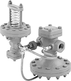
Back-Pressure-Regulating Valves for Water and Oil
- For Use With: Water, Oil
- Temperature Range: -40° to 200° F
Commonly used as bypass lines after centrifugal, reciprocating, and rotary pumps, these valves obstruct flow to maintain sufficient operating pressure in your system. If the system pressure exceeds the set pressure, they exhaust through the threaded relief port. Adjust the set pressure within the range. Valves have a cast iron body that absorbs vibration from pressure changes to reduce wear and noise in your pipeline.
![]() For technical drawings and 3-D models, click on a part number.
For technical drawings and 3-D models, click on a part number.
Inlet | Outlet | Relief Port | ||||||||
|---|---|---|---|---|---|---|---|---|---|---|
| Pipe Size | Location | Max. Pressure, psi | Pipe Size | Location | Pipe Size | Location | End-to-End Lg. | Choose an Outlet Pressure Range, psi | Each | |
NPT Female | ||||||||||
Cast Iron Body—Nickel Alloy Diaphragm and 303 Stainless Steel Seal | ||||||||||
| 1/2 | Side | 400 | 1/2 | Side | 1/2 | Bottom | 2 7/8" | 0000000 | 0000000 | |
| 1 1/4 | Side | 400 | 1 1/4 | Side | 1 1/4 | Bottom | 4 1/4" | 0000000 | 00000000 | |
| 1 1/2 | Side | 400 | 1 1/2 | Side | 1 1/2 | Bottom | 5" | 0000000 | 00000000 | |
| 2 | Side | 400 | 2 | Side | 2 | Bottom | 5" | 0000000 | 00000000 | |
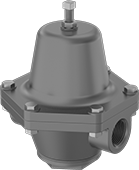
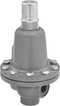
Large-Diameter Remote-Discharge Fast-Acting
Pressure-Relief Valves for Air and Inert Gas
- For Use With: Air, Inert Gas
- Temperature Range: -20° to 406° F
Commonly used with high-volume blowers, compressors, and air-powered conveyors, these valves quickly relieve a large amount of air in systems with a pipe size of 2 or greater. They spring fully open at the set pressure and remain open until the system pressure is restored below the set pressure. Attach a drain line to the threaded relief port for remote discharge. Valves have a cast iron body to absorb vibration for reduced noise and wear in your pipeline.
![]() For technical drawings and 3-D models, click on a part number.
For technical drawings and 3-D models, click on a part number.
Inlet | Relief Port | ||||||||||
|---|---|---|---|---|---|---|---|---|---|---|---|
| Pipe Size | Location | Maximum Pressure, psi | Pipe Size | Location | Temperature Range, ° F | Overall Ht. | Test Mechanism | Valve Type | Choose a Set Pressure, psi | Each | |
NPT Male Inlet and NPT Female Relief Port | |||||||||||
Cast Iron Body—Bronze Seal | |||||||||||
| 2 | Bottom | 60 | 2 | Side | -20° to 406° | 7" | T-Handle | Pop Safety | 0000000 | 0000000 | |
| 2 1/2 | Bottom | 60 | 2 1/2 | Side | -20° to 406° | 8" | T-Handle | Pop Safety | 0000000 | 000000 | |
| 3 | Bottom | 60 | 3 | Side | -20° to 406° | 9" | T-Handle | Pop Safety | 0000000 | 000000 | |
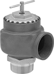
Large-Diameter Remote-Discharge ASME-Code
Fast-Acting Pressure-Relief Valves for Air and Inert Gas
- For Use With: Air, Inert Gas
- Specifications Met: ASME BPVC.VIII
- Temperature Range: -20° to 406° F
These valves meet ASME Code Section VIII for use with air and inert gas pressure vessels. Commonly used with high-volume blowers, compressors, and air-powered conveyors, they quickly relieve a large amount of air in systems with a pipe size of 2 or greater. They spring fully open at the set pressure and remain open until the system pressure is restored below the set pressure. Attach a drain line to the threaded relief port for remote discharge. Valves have a cast iron body to absorb vibration for reduced noise and wear in your pipeline.
![]() For technical drawings and 3-D models, click on a part number.
For technical drawings and 3-D models, click on a part number.
Inlet | Relief Port | |||||||||
|---|---|---|---|---|---|---|---|---|---|---|
| Pipe Size | Location | Maximum Pressure, psi | Pipe Size | Location | Overall Ht. | Test Mechanism | Valve Type | Choose a Set Pressure, psi | Each | |
NPT Male Inlet and NPT Female Relief Port | ||||||||||
Cast Iron Body—Bronze Seal | ||||||||||
| 2 | Bottom | 60 | 2 | Side | 7" | T-Handle | Pop Safety | 0000000 | 0000000 | |
| 2 1/2 | Bottom | 60 | 2 1/2 | Side | 8" | T-Handle | Pop Safety | 0000000 | 000000 | |
| 3 | Bottom | 60 | 3 | Side | 9" | T-Handle | Pop Safety | 0000000 | 000000 | |
Pressure-Regulating Inline Hydraulic Valves
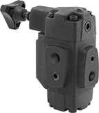
When input pressure varies, use these valves to maintain a consistent pressure. They are often placed after a directional-control valve and before an actuator, such as a cylinder. They have an indicator/gauge port for the inlet and one for the outlet so you can monitor that output pressure remains steady.
![]() For technical drawings and 3-D models, click on a part number.
For technical drawings and 3-D models, click on a part number.
Inlet/Outlet Connection | Relief Connection | O'all | |||||||
|---|---|---|---|---|---|---|---|---|---|
| Pipe Size | Dash Size | Pipe Size | Dash Size | Lg. | Wd. | Ht. | Choose a Set Pressure Range, psi | Each | |
NPT Female Inlet and Relief Port | |||||||||
Cast Iron Body | |||||||||
| 3/4 | 12 | 1/4 | 04 | 5 7/8" | 3 3/4" | 7 1/8" | 000000 | 0000000 | |