Flow Control Flow Control |
---|
|
Material Material |
---|
|
Flow Input to Output Ratio Flow Input to Output Ratio |
---|
|
|
|
For Air Type For Air Type |
---|
|
Overall Width Overall Width |
---|
|
|
|
Overall Length Overall Length |
---|
|
|
|
Maximum Particle Size Maximum Particle Size |
---|
|
More
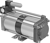
Ensure sufficient pressure to operate air-powered tools and machines. Pressure boosters compress the air supply, which increases air pressure. To maximize performance and service life, install a filter inline before the booster to remove particles down to the maximum particle size. Do not use boosters for tank capacities larger than specified.
Adjustable boosters have an integral regulator so you can fine-tune the output pressure. They come with pressure gauges on the inlet and outlet.
Boosters with 3/8 NPT female inlet and outlet require compressed air to operate—they have a drive inlet and a pilot inlet that control the booster.
Input to Output Ratio | Pressure, psi | Overall | Mounting Holes | |||||||||||||
---|---|---|---|---|---|---|---|---|---|---|---|---|---|---|---|---|
Pressure | Flow | Input | Output | For Tank Cap., gal. | Max. Particle Size, µm | No. of Inlets | Duty Cycle | Max. Temp., °F | Lg. | Wd. | Ht. | No. of | Dia. | Mounting Fasteners Included | Each | |
Adjustable | ||||||||||||||||
1/4 NPTF Female Supply Inlet and Outlet | ||||||||||||||||
1:2 | 2:1 | 14.5-145 | 29-290 | 1.32-2.64 | 5 | 1 | __ | 122° | 6" | 5" | 4 1/2" | 4 | 0.22" | No | 0000000 | 0000000 |
1:4 | 4:1 | 14.5-145 | 29-290 | 1.32-2.64 | 5 | 1 | __ | 122° | 6" | 5" | 4 1/2" | 4 | 0.22" | Yes | 0000000 | 000000 |
Fixed | ||||||||||||||||
1/4 NPT Female Supply Inlet and Outlet | ||||||||||||||||
1:2 | 2:1 | 10-100 | 20-200 | 0-5 | 40 | 1 | 4 Minutes On, 4 Minutes Off | Not Rated | 7 1/2" | 5 1/4" | 4 1/2" | 4 | 0.28" | No | 0000000 | 000000 |
1:4 | 4:1 | 10-100 | 40-400 | 0-5 | 40 | 1 | 4 Minutes On, 4 Minutes Off | Not Rated | 7 1/2" | 5 1/4" | 4 1/2" | 4 | 0.28" | No | 0000000 | 000000 |
3/8 NPT Female Supply Inlet and Outlet | ||||||||||||||||
2:1 | 2:1 | 25-150 | 30-300 | 4-60 | 40 | 1 | 30 Minutes On, 30 Minutes Off | 180° | 17" | 8" | 11" | 4 | 0.38" | No | 0000000 | 00000000 |
5:1 | 7:1 | 30-870 | 90-870 | 1-15 | 40 | 2 | 30 Minutes On, 30 Minutes Off | 140° | 24" | 9" | 9" | 4 | 0.44" | No | 0000000 | 00000000 |
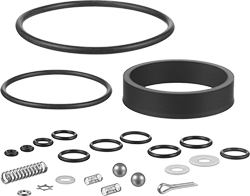
For Pressure Input to Output Ratio | For Inlet Pipe Size | For Inlet Thread Type | Includes | Each | |
Air Drive Repair Kit | |||||
---|---|---|---|---|---|
1:2, 1:4 | 1/4 | NPT | Bearing, Nine O-Rings, Spring, Star Washer | 00000000 | 000000 |
Check Valve Repair Kit | |||||
1:2, 1:4 | 1/4 | NPT | Three O-Rings, Two Balls, Two Seat Balls, Two Springs | 00000000 | 00000 |
Complete Repair Kit | |||||
1:2 | 1/4 | NPT | Bearing, Cotter Pin, High-Pressure Seal, Star Washer, Thirteen O-Rings, Three Springs, Two Balls, Two Seat Balls | 00000000 | 000000 |
1:4 | 1/4 | NPT | Bearing, Cotter Pin, High-Pressure Seal, Star Washer, Thirteen O-Rings, Three Springs, Two Balls, Two Seat Balls | 00000000 | 000000 |
High-Pressure Section Repair Kit | |||||
1:2 | 1/4 | NPT | Cotter Pin, High-Pressure Seal, O-Ring | 00000000 | 00000 |
1:4 | 1/4 | NPT | Cotter Pin, High-Pressure Seal, O-Ring | 00000000 | 00000 |
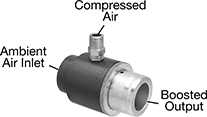
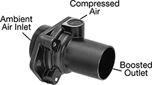
Create a high-flow air stream from your compressed air supply. Flow boosters draw in ambient air, which amplifies compressed air flow. To maximize performance and service life, install a filter inline before the booster to remove particles down to the maximum particle size. Use hose clamps (not included) to connect hose or duct to the inlet or outlet.
Adjustable boosters allow you to fine-tune the flow—rotate the knurled ring to change the amount of ambient air drawn into the booster.
Boosters with flange mount easily near your equipment.
Input | Ambient Air Inlet | Outlet | Overall | Flange | Mounting Holes | ||||||||||||
---|---|---|---|---|---|---|---|---|---|---|---|---|---|---|---|---|---|
Flow Input to Output Ratio | Flow Rate @ 90 psi | Pressure, psi | Output Flow Rate @ 90 psi | Max. Particle Size, µm | Connection Type | For Tube ID | Connection Type | For Tube ID | Lg. | Wd. | Ht. | Lg. | No. of | Dia. | Mounting Fasteners Included | Each | |
Adjustable | |||||||||||||||||
1/8 NPT Male Supply Inlet | |||||||||||||||||
1:6 | 13 cfm | 5-150 | 35-65 cfm | 20 | Clamp On | 0.75" | Clamp On | 0.75" | 2 9/16" | 1" | __ | __ | __ | __ | __ | 00000000 | 000000 |
1:8 | 13 cfm | 5-150 | 37-79 cfm | 20 | Clamp On | 0.75" | Clamp On | 0.75" | 2 9/16" | 1 1/8" | __ | __ | __ | __ | __ | 00000000 | 00000 |
1:12 | 25 cfm | 5-150 | 155-250 cfm | 20 | Clamp On | 1.125" | Clamp On | 1.125" | 2 5/8" | 1 1/2" | __ | __ | __ | __ | __ | 00000000 | 00000 |
1/4 NPT Male Supply Inlet | |||||||||||||||||
1:15 | 28 cfm | 5-150 | 200-400 cfm | 20 | Clamp On | 1.5" | Clamp On | 1.5" | 3 1/4" | 2" | __ | __ | __ | __ | __ | 00000000 | 000000 |
1:20 | 29 cfm | 5-150 | 330-520 cfm | 20 | Clamp On | 2" | Clamp On | 2" | 3 1/4" | 2 1/2" | __ | __ | __ | __ | __ | 00000000 | 000000 |
1:22 | 40 cfm | 5-150 | 380-840 cfm | 20 | Clamp On | 2.5" | Clamp On | 2.5" | 4 5/8" | 3" | __ | __ | __ | __ | __ | 00000000 | 000000 |
3/8 NPT Male Supply Inlet | |||||||||||||||||
1:25 | 51 cfm | 5-150 | 700-1,200 cfm | 20 | Clamp On | 3.5" | Clamp On | 3.5" | 5 1/4" | 4" | __ | __ | __ | __ | __ | 00000000 | 000000 |
Fixed | |||||||||||||||||
1/8 NPT Female Supply Inlet | |||||||||||||||||
1:4 | 8 cfm | 10-200 | 29.2 cfm | 5 | Clamp On | 0.75" | Clamp On | 0.75" | 2 1/2" | 1 3/8" | __ | __ | __ | __ | __ | 0000000 | 00000 |
1:4 | 8 cfm | 10-200 | 29.2 cfm | 5 | Clamp On | 1.33" | Clamp On | 0.75" | 2 1/8" | 1 3/8" | __ | __ | __ | __ | __ | 0000000 | 00000 |
1:4 | 17 cfm | 10-200 | 62 cfm | 5 | Clamp On | 1.33" | Clamp On | 0.5" | 2 5/8" | 1 3/8" | __ | __ | __ | __ | __ | 0000000 | 00000 |
Fixed with Flange | |||||||||||||||||
1/8 NPT Female Supply Inlet | |||||||||||||||||
1:10 | 6.5 cfm | 5-150 | 42 cfm | 20 | Clamp On | 0.98" | Clamp On | 0.73" | 2 3/16" | 2 5/16" | 1.3" | 2.3" | 2 | 0.2" | No | 000000 | 00000 |
1/4 NPT Female Supply Inlet | |||||||||||||||||
1:15 | 11 cfm | 5-150 | 155 cfm | 20 | Clamp On | 1.5" | Clamp On | 1.22" | 2 3/4" | 3" | 1.9" | 3" | 2 | 0.27" | No | 0000000 | 000000 |
3/8 NPT Female Supply Inlet | |||||||||||||||||
1:16 | 21 cfm | 5-150 | 325 cfm | 20 | Clamp On | 2.95" | Clamp On | 2" | 3 3/4" | 4 1/8" | 3.2" | 4.1" | 2 | 0.27" | No | 0000000 | 000000 |
1/2 NPT Female Supply Inlet | |||||||||||||||||
1:17 | 42 cfm | 5-150 | 615 cfm | 20 | Clamp On | 4.92" | Clamp On | 4" | 7" | 8 1/2" | 5.9" | 8.5" | 2 | 0.53" | No | 0000000 | 000000 |
Use a low-flow air pilot signal with an air supply to produce flow up to 50 cfm to actuate valves and other air-powered system components. To maximize performance and service life, install a filter inline before the booster to remove particles down to the maximum particle size.
Boosters with a 1:1 pressure input to output ratio maintain pressure between the air supply inlet and the boosted output.
Boosters with 1:3 and 1:6 pressure input to output ratios increase pressure between the air supply inlet and the boosted output.
Pressure, psi | Air Pilot | Gauge Port | Overall | Mounting Holes | ||||||||||||||||
---|---|---|---|---|---|---|---|---|---|---|---|---|---|---|---|---|---|---|---|---|
Pressure Input to Output Ratio | Input | Output | Max. Air Pilot Signal | Max. Particle Size, µm | Pipe Size | Thread Type | Gender | Pipe Size | Thread Type | Gender | Exhaust Air Flow, scfm | Max. Temp., °F | Lg. | Wd. | Ht. | No. of | Dia. | Mounting Fasteners Included | Each | |
Fixed | ||||||||||||||||||||
1/4 NPT Female Supply Inlet and Outlet | ||||||||||||||||||||
1:1 | 0-250 | 0-150 | 150 | 40 | 1/4 | NPT | Female | 1/4 | NPT | Female | 15 | 160° | 3" | 3" | 4" | 6 | 0.33" | No | 0000000 | 0000000 |
1:3 | 0-250 | 0-150 | 50 | 40 | 1/4 | NPT | Female | 1/4 | NPT | Female | 15 | 160° | 3" | 3" | 4" | 6 | 0.33" | No | 0000000 | 000000 |
1:6 | 0-250 | 0-150 | 25 | 40 | 1/4 | NPT | Female | 1/4 | NPT | Female | 10 | 160° | 3" | 3" | 4" | 6 | 0.33" | No | 0000000 | 000000 |
3/8 NPT Female Supply Inlet and Outlet | ||||||||||||||||||||
1:1 | 0-250 | 0-150 | 150 | 40 | 1/4 | NPT | Female | 1/4 | NPT | Female | 15 | 160° | 3" | 3" | 4" | 6 | 0.33" | No | 0000000 | 000000 |
Optional Mounting Bracket | 000000 | Each | 000000 |
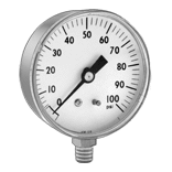
With a greater flow capacity than our standard precision compressed air regulators, use these regulators to adjust and maintain air pressure in sensitive high-flow applications where constant, consistent pressure is important. Install in your air line after filters.
Relieving regulators exhaust when the downstream pressure exceeds the set pressure.
Nonrelieving regulators do not exhaust excess downstream pressure.
BSPP threads are also known as G threads.
Pressure gauges are for use with regulators with NPT threading.
Mounting brackets (sold separately) allow you to attach the regulator to a wall or equipment.
Regulators | ||||||||||||||
---|---|---|---|---|---|---|---|---|---|---|---|---|---|---|
Pipe Size | Overall | Mounting Brackets | ||||||||||||
Inlet | Outlet | Max. Flow Rate | Max. Pressure, psi | Gauge Included | No. of Gauge Ports | Wd. | Ht. | Max. Temp., °F | Regulating Accuracy | Choose a Pressure Regulating Range, psi | Each | Each | ||
Aluminum Housing—BSPP Female Inlet and Outlet | ||||||||||||||
Relieving | ||||||||||||||
1/4 | 1/4 | 80 scfm @ 100 psi | 250 | No | 2 | 3" | 6 1/8" | 160° | ±0.05% | 00000000 | 000000 | 000000 | 000000 | |
3/8 | 3/8 | 80 scfm @ 100 psi | 250 | No | 2 | 3" | 6 1/8" | 160° | ±0.05% | 00000000 | 00000 | 000000 | 00000 | |
1/2 | 1/2 | 80 scfm @ 100 psi | 250 | No | 2 | 3" | 6 1/8" | 160° | ±0.05% | 00000000 | 000000 | 000000 | 00000 | |
Nonrelieving | ||||||||||||||
1/4 | 1/4 | 80 scfm @ 100 psi | 250 | No | 2 | 3" | 6 1/8" | 160° | ±0.05% | 00000000 | 000000 | 000000 | 00000 | |
3/8 | 3/8 | 80 scfm @ 100 psi | 250 | No | 2 | 3" | 6 1/8" | 160° | ±0.05% | 00000000 | 000000 | 000000 | 00000 | |
1/2 | 1/2 | 80 scfm @ 100 psi | 250 | No | 2 | 3" | 6 1/8" | 160° | ±0.05% | 00000000 | 000000 | 000000 | 00000 | |
Aluminum Housing—NPT Female Inlet and Outlet | ||||||||||||||
Relieving | ||||||||||||||
1/4 | 1/4 | 80 scfm @ 100 psi | 250 | No | 2 | 3" | 6 1/8" | 160° | ±0.05% | 000000 | 00000 | 000000 | 00000 | |
1/4 | 1/4 | 100 scfm @ 100 psi | 250 | No | 2 | 4" | 7 5/8" | 200° | ±0.1% | 00000000 | 000000 | 00000000 | 00000 | |
3/8 | 3/8 | 80 scfm @ 100 psi | 250 | No | 2 | 3" | 6 1/8" | 160° | ±0.05% | 000000 | 00000 | 000000 | 00000 | |
1/2 | 1/2 | 80 scfm @ 100 psi | 250 | No | 2 | 3" | 6 1/8" | 160° | ±0.05% | 000000 | 000000 | 000000 | 00000 | |
1/2 | 1/2 | 80 scfm @ 100 psi | 250 | No | 2 | 3" | 6 1/8" | 160° | ±0.05% | 0-2 | 0000000 | 000000 | 000000 | 00000 |
1/2 | 1/2 | 225 scfm @ 100 psi | 250 | No | 2 | 4" | 7 5/8" | 200° | ±0.1% | 00000000 | 000000 | 00000000 | 00000 | |
3/4 | 3/4 | 250 scfm @ 100 psi | 250 | No | 2 | 4" | 7 5/8" | 200° | ±0.1% | 00000000 | 000000 | 00000000 | 00000 | |
Nonrelieving | ||||||||||||||
1/4 | 1/4 | 80 scfm @ 100 psi | 250 | No | 2 | 3" | 6 1/8" | 160° | ±0.05% | 00000000 | 000000 | 000000 | 00000 | |
1/4 | 1/4 | 100 scfm @ 100 psi | 250 | No | 2 | 4" | 7 5/8" | 200° | ±0.1% | 00000000 | 000000 | 00000000 | 00000 | |
3/8 | 3/8 | 80 scfm @ 100 psi | 250 | No | 2 | 3" | 6 1/8" | 160° | ±0.05% | 00000000 | 000000 | 000000 | 00000 | |
1/2 | 1/2 | 80 scfm @ 100 psi | 250 | No | 2 | 3" | 6 1/8" | 160° | ±0.05% | 00000000 | 000000 | 000000 | 00000 | |
1/2 | 1/2 | 225 scfm @ 100 psi | 250 | No | 2 | 4" | 7 5/8" | 200° | ±0.1% | 00000000 | 000000 | 00000000 | 00000 | |
3/4 | 3/4 | 250 scfm @ 100 psi | 250 | No | 2 | 4" | 7 5/8" | 200° | ±0.1% | 00000000 | 000000 | 00000000 | 00000 |
Prevent unauthorized adjustment and unintentional pressure changes with these regulators. Use them in your air line to adjust and maintain the pressure of your compressed air. All are relieving regulators, so they exhaust when the downstream pressure exceeds the set pressure. Install in your air line after filters.
Mounting brackets allow you to attach the regulator to a wall or equipment.
For technical drawings and 3-D models, click on a part number.
Regulators | |||||||||||||
---|---|---|---|---|---|---|---|---|---|---|---|---|---|
Pipe Size | Overall | Mounting Brackets | |||||||||||
Inlet | Outlet | Max. Flow Rate | Max. Pressure, psi | Gauge Included | Wd. | Ht. | Max. Temp., °F | Regulating Accuracy | Pressure Regulating Range, psi | Each | Each | ||
With Knob-Locking Clip | |||||||||||||
Aluminum Housing—NPT Female Inlet and Outlet | |||||||||||||
1/4 | 1/4 | 86 scfm @ 100 psi | 250 | Yes | 2 1/4" | 4 7/8" | 140° | ±2% | 0-140 | 0000000 | 000000 | 0000000 | 000000 |
3/8 | 3/8 | 179 scfm @ 100 psi | 250 | Yes | 2 7/8" | 5 1/2" | 140° | ±2% | 0-140 | 0000000 | 00000 | 0000000 | 00000 |
1/2 | 1/2 | 210 scfm @ 100 psi | 250 | Yes | 2 7/8" | 5 1/2" | 140° | ±2% | 0-140 | 0000000 | 00000 | 0000000 | 00000 |
3/4 | 3/4 | 290 scfm @ 100 psi | 250 | Yes | 3 5/8" | 7 1/4" | 140° | ±2% | 0-140 | 0000000 | 000000 | 0000000 | 00000 |
1 | 1 | 290 scfm @ 100 psi | 250 | Yes | 3 5/8" | 7 1/4" | 140° | ±2% | 0-140 | 0000000 | 000000 | 0000000 | 00000 |