


Material Material | Show |
|---|
|
Material Material | Hide |
|---|
Opening/Closing Action Opening/Closing Action |
|---|
|
DFARS (Defense Acquisition Regulations Supplement) DFARS (Defense AcquisitionRegulations Supplement) |
|---|
Mounting Hole Center-to-Center Length Mounting Hole Center-to-Center Length |
|---|
|
|
|
For Door Swing Direction For Door Swing Direction |
|---|
|
For Shaft Diameter For Shaft Diameter |
|---|
Manufacturer Manufacturer |
|---|
|
For Shaft Type For Shaft Type |
|---|
| Keyed | |
Useful Life Useful Life |
|---|
|
Mounting Hardware Included Mounting Hardware Included |
|---|
|
RoHS (Restriction of Hazardous Substances) RoHS (Restriction ofHazardous Substances) |
|---|
|
REACH (Registration, Evaluation, Authorization and Restriction of Chemicals) REACH (Registration,Evaluation, Authorization and Restriction of Chemicals) |
|---|
|
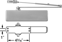
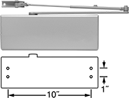
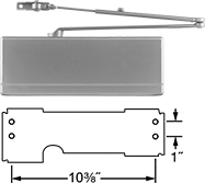
About Door Closers
When replacing an existing closer, remove the cover and match the model number and/or mounting hole pattern to a closer in our offering. Or, use one of our closers and a universal mounting plate that matches most hole patterns.
If you are installing a new closer, choose one that works for your door width. Due to added resistance from wind, closers typically accommodate smaller exterior doors than interior doors.
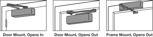
There are three typical mounting positions for door closers; many of our closers are versatile and can be mounted in any of these positions. To determine opening direction, stand on the side of the door where the closer will be mounted. If the door opens towards you it opens in; opens away from you it opens out.
Door Mount, Opens In—Also known as regular arm mount, this position allows the door to open in toward the closer.
Door Mount, Opens Out—Also known as parallel arm mount, the arm lays parallel with the door in the closed position.
Frame Mount, Opens Out—Also known as top frame mount, this position is often used for exterior doors.
About Shaft Couplings
More
Door Stops for Sliding Doors
Keep sliding doors and panels from damaging walls and door frames. Mount these stops with screws.
Styles 2 and 3 mount on the floor.
![]() For technical drawings and 3-D models, click on a part number.
For technical drawings and 3-D models, click on a part number.
For Max. Door | ||||||||||
|---|---|---|---|---|---|---|---|---|---|---|
| Style | Lg. | Wd. | Ht. | Thick. | Weight, lbs. | Material | Mounting Fasteners Included | Mounting Screw Size | Each | |
Unthreaded Hole | ||||||||||
| 2 | 4 5/8" | 4 5/8" | 2 1/4" | Any | 5,000 | Iron | No | No. 18 | 000000 | 000000 |
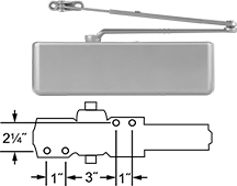
Freezer Door Closers
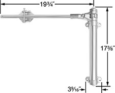
Often used on large freezer and cold-storage doors, these closers are designed for doors that weigh 200 lbs. or more. Mount them to the face of your door and frame just above the door's lowest hinge. These free-moving closers pull doors shut after you've opened them. They are reversible for right or left door-swing directions. Offset is the space between the door face and the frame when the door is closed.
| For Door Swing Direction | For Max. Door Offset | Projection | Opening/Closing Action | Mounting Location | Range of Motion | Mounting Hardware Included | Material | Finish | Each | |
| Reversible | 7/8" | 2 7/16" | Free Moving | Door, Frame | 175° | Yes | Iron | Zinc | 0000000 | 0000000 |
High-Traffic Door Closers
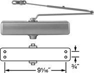
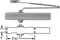
For frequently used doors, these closers last twice as long as standard door closers. They can replace Yale, Dorma, Falcon, Stanley, Parker, and Cal-Royal models with the same mounting hole pattern. All meet ANSI A156.4 Grade 1 durability, strength, and performance standards for door controls. Closers that meet UL 10C for fire-rated doors meet positive pressure fire test standards.
To determine door swing direction, stand on the side of the door where it swings away from you. If it opens to the right, select a right closer; if it opens to the left, select a left closer. Reversible closers are for right or left door-swing directions.
Free-moving closers pull doors shut after you've opened them.
Hold-open closers hold doors open until you close them with a slight push or pull on the door.
Closers with a delayed close hold doors open for a set amount of time before closing.
For Door Wd. | Opening Direction | |||||||||||
|---|---|---|---|---|---|---|---|---|---|---|---|---|
| Interior | Exterior | For Door Swing Direction | Opening/Closing Action | Delayed Closing Time, sec. | Door Mount | Frame Mount | Range of Motion | Mounting Hardware Included | Specifications Met | Choose a Finish | Each | |
LCN 1261 | ||||||||||||
| 24"-54" | 24"-42" | Reversible | Free Moving | __ | Opens In, Opens Out | Opens Out | 180° | Yes | ANSI A156.4 Grade 1 UL 10C for Fire-Rated Doors UL Listed | 0000000 | 0000000 | |
| 24"-54" | 24"-42" | Reversible | Hold Open | __ | Opens In, Opens Out | Opens Out | 180° | Yes | ANSI A156.4 Grade 1 | 0000000 | 000000 | |
LCN 1460/1461 | ||||||||||||
| 24"-60" | 24"-48" | Reversible | Free Moving | __ | Opens In, Opens Out | Opens Out | 180° | Yes | ANSI A156.4 Grade 1 UL 10C for Fire-Rated Doors UL Listed | 0000000 | 000000 | |
| 24"-60" | 24"-48" | Reversible | Hold Open | __ | Opens In, Opens Out | Opens Out | 180° | Yes | ANSI A156.4 Grade 1 | 0000000 | 000000 | |
| 24"-60" | 24"-48" | Reversible | Hold Open Delayed Close | 5 to 60 | Opens In, Opens Out | Opens Out | 180° | Yes | ANSI A156.4 Grade 1 | 0000000 | 000000 | |
| 24"-60" | 24"-48" | Reversible | Delayed Close | 5 to 60 | Opens In, Opens Out | Opens Out | 180° | Yes | ANSI A156.4 Grade 1 UL 10C for Fire-Rated Doors UL Listed | 0000000 | 000000 | |
LCN 4011 | ||||||||||||
| 24"-54" | 24"-42" | Left | Free Moving | __ | Opens In | __ | 140° | Yes | ANSI A156.4 Grade 1 UL 10C for Fire-Rated Doors UL Listed | 0000000 | 000000 | |
| 24"-54" | 24"-42" | Left | Hold Open | __ | Opens In | __ | 140° | Yes | ANSI A156.4 Grade 1 | 0000000 | 000000 | |
| 24"-54" | 24"-42" | Left | Hold Open Delayed Close | 5 to 60 | Opens In | __ | 140° | Yes | ANSI A156.4 Grade 1 | 0000000 | 000000 | |
| 24"-54" | 24"-42" | Left | Delayed Close | 5 to 60 | Opens In | __ | 140° | Yes | ANSI A156.4 Grade 1 UL 10C for Fire-Rated Doors UL Listed | 0000000 | 000000 | |
| 24"-54" | 24"-42" | Right | Free Moving | __ | Opens In | __ | 140° | Yes | ANSI A156.4 Grade 1 UL 10C for Fire-Rated Doors UL Listed | 0000000 | 000000 | |
| 24"-54" | 24"-42" | Right | Hold Open | __ | Opens In | __ | 140° | Yes | ANSI A156.4 Grade 1 | 0000000 | 000000 | |
| 24"-54" | 24"-42" | Right | Hold Open Delayed Close | 5 to 60 | Opens In | __ | 140° | Yes | ANSI A156.4 Grade 1 | 0000000 | 000000 | |
| 24"-54" | 24"-42" | Right | Delayed Close | 5 to 60 | Opens In | __ | 140° | Yes | ANSI A156.4 Grade 1 UL 10C for Fire-Rated Doors UL Listed | 0000000 | 000000 | |
LCN 4021 | ||||||||||||
| 24"-54" | 24"-42" | Left | Free Moving | __ | __ | Opens Out | 180° | Yes | ANSI A156.4 Grade 1 UL 10C for Fire-Rated Doors UL Listed | 0000000 | 000000 | |
| 24"-54" | 24"-42" | Left | Hold Open | __ | __ | Opens Out | 140° | Yes | ANSI A156.4 Grade 1 | 0000000 | 000000 | |
| 24"-54" | 24"-42" | Right | Free Moving | __ | __ | Opens Out | 180° | Yes | ANSI A156.4 Grade 1 UL 10C for Fire-Rated Doors UL Listed | 0000000 | 000000 | |
| 24"-54" | 24"-42" | Right | Hold Open | __ | __ | Opens Out | 140° | Yes | ANSI A156.4 Grade 1 | 0000000 | 000000 | |
LCN 4040XP | ||||||||||||
| 24"-60" | 24"-48" | Reversible | Free Moving | __ | Opens In, Opens Out | Opens Out | 120° | Yes | ANSI A156.4 Grade 1 UL 10C for Fire-Rated Doors UL Listed | 0000000 | 000000 | |
| 24"-60" | 24"-48" | Reversible | Hold Open | __ | Opens In, Opens Out | Opens Out | 120° | Yes | ANSI A156.4 Grade 1 | 0000000 | 000000 | |
LCN 4111 | ||||||||||||
| 28"-54" | 28"-42" | Left | Free Moving | __ | Opens Out | __ | 180° | Yes | ANSI A156.4 Grade 1 UL 10C for Fire-Rated Doors UL Listed | 0000000 | 000000 | |
| 28"-54" | 28"-42" | Left | Hold Open | __ | Opens Out | __ | 180° | Yes | ANSI A156.4 Grade 1 | 0000000 | 000000 | |
| 28"-54" | 28"-42" | Right | Free Moving | __ | Opens Out | __ | 180° | Yes | ANSI A156.4 Grade 1 UL 10C for Fire-Rated Doors UL Listed | 0000000 | 000000 | |
| 28"-54" | 28"-42" | Right | Hold Open | __ | Opens Out | __ | 180° | Yes | ANSI A156.4 Grade 1 | 0000000 | 000000 | |
Corbin Russwin DC3000 | ||||||||||||
| 28"-54" | 30"-48" | Reversible | Free Moving | __ | Opens In, Opens Out | Opens Out | 180° | Yes | ANSI A156.4 Grade 1 UL 10C for Fire-Rated Doors UL Listed | 0000000 | 000000 | |
| 28"-54" | 30"-48" | Reversible | Hold Open | __ | Opens In, Opens Out | Opens Out | 180° | Yes | ANSI A156.4 Grade 1 | 0000000 | 000000 | |
Corbin Russwin DC6200 | ||||||||||||
| 28"-54" | 30"-48" | Reversible | Free Moving | __ | Opens Out | __ | 180° | Yes | ANSI A156.4 Grade 1 UL 10C for Fire-Rated Doors UL Listed | Gray | 0000000 | 000000 |
| 28"-54" | 30"-48" | Reversible | Hold Open | __ | Opens Out | __ | 180° | Yes | ANSI A156.4 Grade 1 UL 10C for Fire-Rated Doors UL Listed | Gray | 0000000 | 000000 |
Corbin Russwin DC8200 | ||||||||||||
| 28"-54" | 30"-48" | Reversible | Free Moving | __ | Opens Out | __ | 180° | Yes | ANSI A156.4 Grade 1 UL 10C for Fire-Rated Doors UL Listed | Gray | 0000000 | 000000 |
| 28"-54" | 30"-48" | Reversible | Hold Open | __ | Opens Out | __ | 180° | Yes | ANSI A156.4 Grade 1 UL 10C for Fire-Rated Doors UL Listed | Gray | 0000000 | 000000 |
Sargent 281 | ||||||||||||
| 32"-48" | 32"-36" | Reversible | Free Moving | __ | Opens In, Opens Out | Opens Out | 180° | Yes | ANSI A156.4 Grade 1 UL 10C for Fire-Rated Doors UL Listed | Gray | 0000000 | 000000 |
| 32"-48" | 32"-36" | Reversible | Hold Open | __ | Opens In, Opens Out | Opens Out | 180° | Yes | ANSI A156.4 Grade 1 UL 10C for Fire-Rated Doors UL Listed | Gray | 0000000 | 000000 |
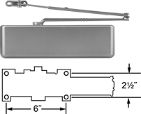
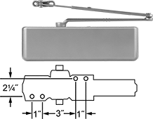
High-Traffic Door Closers with Built-In Stop
A built-in stop prevents doors from opening too far—good when wall- or floor-stops can’t be used. Designed for frequently used doors, these closers last twice as long as standard door closers. They can replace Yale, Dorma, Falcon, Stanley, Parker, and Cal-Royal models with the same mounting hole pattern. These closers are reversible for right or left door-swing directions. All meet ANSI A156.4 Grade 1 durability, strength, and performance standards for door controls. Closers that meet UL 10C for fire-rated doors meet positive pressure fire test standards.
Free-moving closers pull doors shut after you've opened them.
Hold-open closers hold doors open until you close them with a slight push or pull on the door.
For Door Wd. | ||||||||||
|---|---|---|---|---|---|---|---|---|---|---|
| Interior | Exterior | For Door Swing Direction | Opening/Closing Action | Door Mount Opening Direction | Range of Motion | Mounting Hardware Included | Specifications Met | Choose a Finish | Each | |
LCN 1460/1461 | ||||||||||
| 24"-60" | 24"-48" | Reversible | Free Moving | Opens Out | 100° | Yes | ANSI A156.4 Grade 1 UL 10C for Fire-Rated Doors UL Listed | 0000000 | 0000000 | |
| 24"-60" | 24"-48" | Reversible | Hold Open | Opens Out | 100° | Yes | ANSI A156.4 Grade 1 | 0000000 | 000000 | |
LCN 4040XP | ||||||||||
| 24"-60" | 24"-48" | Reversible | Free Moving | Opens Out | 110° | Yes | ANSI A156.4 Grade 1 UL 10C for Fire-Rated Doors UL Listed | 0000000 | 000000 | |
| 24"-60" | 24"-48" | Reversible | Hold Open | Opens Out | 110° | Yes | ANSI A156.4 Grade 1 | 0000000 | 000000 | |
Vibration-Damping Flexible Shaft Couplings
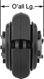
Coupling Shown
Assembled
A flexible tire on these couplings safeguards components on your shafts by reducing vibration and shock.
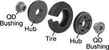
A complete coupling consists of two hubs, one tire, and two quick-disconnect bushings.
Quick-disconnect bushings are easy to install and remove. Tighten their cap screws to secure them to your shafts. For information on quick-disconnect bushing styles, see Quick-Disconnect (QD) Bushings.
![]() For technical drawings and 3-D models, click on a part number.
For technical drawings and 3-D models, click on a part number.
Buna-N Rubber Tires | ||||||||||||||||
|---|---|---|---|---|---|---|---|---|---|---|---|---|---|---|---|---|
Iron and Steel Hubs | Misalignment Capability | Quick-Disconnect (QD) Bushings | ||||||||||||||
| O'all Lg. | OD | For Motion Type | Each | Max. Speed, rpm | Max. Torque, in.-lbs. | Parallel | Angular | Axial | Temp. Range, °F | Each | Bushing Style | For Shaft Dia. | Each | |||
| 3 1/4" | 5 1/4" | Continuous | 0000000 | 000000 | 4,500 | 900 | 0.125" | 4° | 0.313" | -65° to 180° | 0000000 | 000000 | JA | 0000000 | 000000 | |
| 3 15/16" | 6 1/2" | Continuous | 0000000 | 00000 | 4,000 | 1,800 | 0.125" | 4° | 0.313" | -65° to 180° | 0000000 | 00000 | SH | 0000000 | 00000 | |
| 4 3/16" | 7 3/8" | Continuous | 0000000 | 000000 | 3,600 | 2,200 | 0.125" | 4° | 0.313" | -65° to 180° | 0000000 | 000000 | SH | 0000000 | 00000 | |
| 4 5/8" | 8 5/16" | Continuous | 0000000 | 000000 | 3,100 | 3,600 | 0.125" | 4° | 0.313" | -65° to 180° | 0000000 | 000000 | SDS | 0000000 | 00000 | |
| 5 11/16" | 9 1/4" | Continuous | 0000000 | 000000 | 2,800 | 4,350 | 0.125" | 4° | 0.313" | -65° to 180° | 0000000 | 000000 | SK | 0000000 | 00000 | |
High-Speed Vibration-Damping Flexible Shaft Couplings
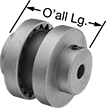
Use these gear-shaped couplings for high-speed and high-torque applications. A rubber center allows flexing so couplings can take on multiple types of misalignment while damping vibration and shock. With no metal-to-metal contact, there’s no need for lubrication. Fasten to your shafts by tightening the set screws, which bite into the shaft to hold it.
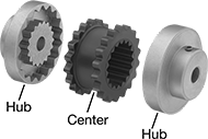
A complete coupling consists of two hubs and one center (each component sold separately).
Hubs have a keyway, except hubs for 1/4" and 3/8" shaft dia. do not have a keyway.
![]() For technical drawings and 3-D models, click on a part number.
For technical drawings and 3-D models, click on a part number.
Centers | |||||||||||||||
|---|---|---|---|---|---|---|---|---|---|---|---|---|---|---|---|
Hubs | Misalignment Capability | ||||||||||||||
| O'all Lg. | OD | For Motion Type | Material | For Shaft Dia. | Each | Max. Speed, rpm | Max. Torque, in.-lbs. | Parallel | Angular | Axial | Temp. Range, °F | Material | Each | ||
| 2 13/16" | 3 1/4" | Continuous | Cast Iron | 0000000 | 000000 | 7,600 | 240 | 0.015" | 1° | 0.125" | -30° to 275° | TPE Rubber | 0000000 | 000000 | |
| 3 1/2" | 4" | Continuous | Cast Iron | 0000000 | 00000 | 6,000 | 450 | 0.015" | 1° | 0.125" | -30° to 275° | TPE Rubber | 0000000 | 00000 | |
| 3 15/16" | 4 5/8" | Continuous | Cast Iron | 000000 | 00000 | 5,250 | 725 | 0.02" | 1° | 0.125" | -30° to 275° | TPE Rubber | 0000000 | 00000 | |
| 4 7/16" | 5 29/64" | Continuous | Cast Iron | 0000000 | 00000 | 4,500 | 1,135 | 0.02" | 1° | 0.125" | -30° to 275° | TPE Rubber | 0000000 | 00000 | |
| 5 1/16" | 6 23/64" | Continuous | Cast Iron | 000000 | 000000 | 3,750 | 1,800 | 0.025" | 1° | 0.125" | -30° to 275° | TPE Rubber | 0000000 | 00000 | |
| 5 11/16" | 7 1/2" | Continuous | Cast Iron | 000000 | 000000 | 3,600 | 2,875 | 0.025" | 1° | 0.125" | -30° to 275° | TPE Rubber | 0000000 | 00000 | |
| 7 1/8" | 8 5/8" | Continuous | Cast Iron | 000000 | 000000 | 3,600 | 4,530 | 0.032" | 1° | 0.125" | -30° to 275° | EPDM Rubber | 0000000 | 000000 | |