


Filter by
Mounting Location
Operation Type
Electrical Connection
Door Switch Speed
Button Material
DFARS Specialty Metals
Finish
Opening/Closing Action
Export Control Classification Number (ECCN)
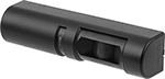
Automatic Door Openers
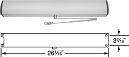 |
Nudge your door and these openers will open it the rest of the way. You can also pair them with automatic door switches and buttons. Their delayed closing action holds the door open for a set amount of time before closing. These openers are for doors that weigh up to 200 lbs. and must be hardwired. They are reversible for right or left door-swing directions.
For Interior Door Wd. | Voltage, V AC | For Door Swing Direction | Opening/Closing Action | Delayed Closing Time, sec. | Opening/Closing Speed | Opening Direction | Range of Motion | Electrical Connection | Mounting Hardware Included | Certification | Material | Each | |||
|---|---|---|---|---|---|---|---|---|---|---|---|---|---|---|---|
LCN 9130 | |||||||||||||||
| 30" to 48" | 120 | Left, Right | Delayed Close | 5 to 30 | Fixed | Opens In | 90° | Wire Leads | Yes | UL Listed | Aluminum-Coated Iron | 10535A12 | 000000000 | ||
LCN 9140 | |||||||||||||||
| 26" to 48" | 120 | Left, Right | Delayed Close | 5 to 30 | Fixed | Opens Out | 90° | Wire Leads | Yes | UL Listed | Aluminum-Coated Iron | 10535A11 | 00000000 | ||
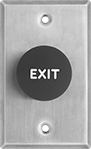
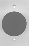
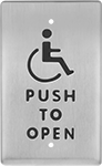
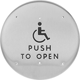
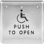
Automatic Door Switches
Instant Open
 |  |  |  | |
Style 1 | Style 2 | Style 3 | Style 4 | Style 5 |
Switches | Surface-Mount Boxes | Square Posts | |||||||||||||||||
|---|---|---|---|---|---|---|---|---|---|---|---|---|---|---|---|---|---|---|---|
Overall | Button | ||||||||||||||||||
Style | Mounting Location | Voltage | Ht. | Wd. | Dia. | Ht. | Wd. | Dia. | Material | Material | Certification | Each | Each | Each | |||||
Push-Button Operation | |||||||||||||||||||
| 1 | Wall | 24V DC | 4 1/2" | 2 3/4" | — | — | — | 1 5/8" | Red Plastic | 304 Stainless Steel | CSA Certified, UL Listed | 13425A11 | 000000 | 13425A62 | 000000 | ——— | 0 | ||
| 2 | Wall | 24V DC | 4 3/4" | 3" | — | — | — | 2 3/8" | Red Plastic | Aluminum | CSA Certified, UL Listed | 13425A42 | 000000 | 13425A62 | 00000 | ——— | 0 | ||
| 3 | Post, Wall | 250V AC | 4 1/2" | 2 3/4" | — | 4 1/2" | 2 3/4" | — | 304 Stainless Steel | 304 Stainless Steel | CSA Certified, UL Listed | 13425A51 | 00000 | 13425A62 | 00000 | 13425A15 | 0000000 | ||
| 4 | Post, Wall | 250V AC | — | — | 6" | — | — | 6" | 304 Stainless Steel | 304 Stainless Steel | CSA Certified, UL Listed | 13425A52 | 00000 | 13425A63 | 00000 | 13425A15 | 000000 | ||
| 5 | Post, Wall | 120V AC, 250V AC, 48V DC | 36" | 6" | — | 36" | 2 1/2" | — | Aluminum | Aluminum | — | 13425A13 | 000000 | ——— | 0 | 13425A14 | 000000 | ||
Time Delay
|  | |
Style 1 | Style 6 | Style 7 |
Switches | Surface-Mount Boxes | |||||||||||||||
|---|---|---|---|---|---|---|---|---|---|---|---|---|---|---|---|---|
Overall | Button | |||||||||||||||
Style | Mounting Location | Voltage | Ht. | Wd. | Ht. | Wd. | Dia. | Material | Material | Certification | Each | Each | ||||
Push-Button Operation | ||||||||||||||||
| 1 | Wall | 24V DC | 4 1/2" | 2 3/4" | — | — | 1 5/8" | Red Plastic | 304 Stainless Steel | CSA Certified, UL Listed | 13425A12 | 0000000 | 13425A62 | 000000 | ||
| 6 | Frame | 120V AC | 4 3/4" | 1 1/2" | 4 3/4" | 1 1/2" | — | 304 Stainless Steel | 304 Stainless Steel | UL Listed | 10535A55 | 000000 | 13425A65 | 00000 | ||
| 7 | Wall | 120V AC | 4 3/4" | 4 3/4" | 4 3/4" | 4 3/4" | — | 304 Stainless Steel | 304 Stainless Steel | UL Listed | 10535A56 | 000000 | 13425A66 | 000000 | ||
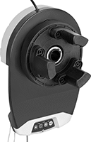
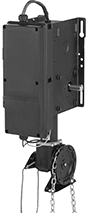
Automatic Openers for Steel Roll-Up Garage Doors
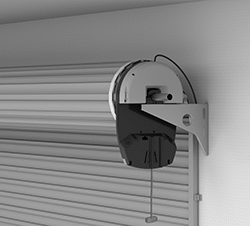 |  |
Shown Installed |
Instead of pulling a chain or handle to open your steel roll-up garage door, push a button. These openers come with everything you need to convert your manual door into an automatic one. Simply slide them over your garage door’s drum axle. For smooth operation, they start and stop slowly to prevent the door from lurching and slamming to the ground. Similar to an automatic garage door, they’ll stop and reverse the door if the light beam sensing switch detects an obstruction in its path. Turn on the safety mode to lock the garage door and limit control to a single master remote. If there's a power failure, disengage these openers to manually open the door.
These openers fit most steel roll-up garage doors, also known as rolling sheet doors, with 9 1/2" or 12" door drums. You can mount them on either side of the door. Do not use these openers with sectional or fabric garage doors.
For Max. Door | |||||||||||||||||
|---|---|---|---|---|---|---|---|---|---|---|---|---|---|---|---|---|---|
Wd., ft. | Ht., ft. | Wt., lb. | Ga. | Power, hp | Voltage, V AC | Cycles per hr. | Ht. | Wd. | Dp. | Mounting Location | Mounting Hardware Included | Material | Includes | Specs. Met | Each | ||
| 13 | 14 | 200 | 26 | 5/16 | 120 | 4 | 15 3/8" | 11 5/8" | 4 1/4" | Left Side, Right Side, Drum | Yes | Plastic | Drum Adapter, Light Beam Sensing Switches, Two Remotes, Wall Button | UL 325 | 7893N11 | 0000000 | |
| 15 | 20 | 350 | 26 | 5/16 | 120 | 13 | 18 3/8" | 12 1/4" | 6" | Left Side, Right Side, Drum | Yes | Plastic | Drum Adapter, Light Beam Sensing Switches, Two Remotes, Wall Button | UL 325 | 7893N12 | 000000 | |
Motion-Sensor Automatic Door Switches
Instant Open
 |
Instant-open switches send a signal to open doors automatically as you approach.
Time Delay
 |
Time-delay switches send a signal when you wave your hand directly in front of them. They're often used in place of push-button wall switches to reduce the spread of germs. They can be set on a delay, so users have adequate time to reach the door before it opens. Mount them to electrical boxes or surface-mount boxes (not included).
Automatic Openers for Roll-Up and Sectional Garage Doors
 |
Also known as jackshafts, these openers will stop and reverse the garage door's downward motion if it encounters an obstruction or the light beam between the opener's sensing switches is interrupted. During a power failure, use the manual chain hoist to move the door. These openers meet UL 325 safety standards for door operators and systems.
Cycles per | ||||||||||||||||||
|---|---|---|---|---|---|---|---|---|---|---|---|---|---|---|---|---|---|---|
For Max. Door Wt., lb. | Power, hp | Voltage, V AC | Hour | Day | Ht. | Wd. | Dp. | Drive Shaft Size | Keyway Size | Mounting Location | Mounting Hardware Included | Material | Roller Chain Trade No. | Includes | Specs. Met | Each | ||
| 700 | 1/2 | 120, 240 | 20 | 90 | 21 3/4" | 9 3/4" | 12" | 1" | 1/4" | Left Side, Right Side, Wall | Yes | Plastic | 50 | Controller, Light Beam Sensing Switches | UL 325 | 12185A95 | 000000000 | |
Outlet-Box-Mount Key Switches
 |
Reset fire panels, or open electromagnetic locks, electric strikes, and automatic door openers. These switches require a key to turn circuits on or off, limiting access and preventing accidental activation. The lock is not included; use a 1 1/4" long mortise lock with a standard cam.
Wire Leads | ||||||||||||||
|---|---|---|---|---|---|---|---|---|---|---|---|---|---|---|
No. of Circuits Controlled | Switch Starting Position | Switch Action | No. of Terminals | Switch Designation | Switching Current @ Voltage | Max. Voltage, V AC | Dia. | No. of | Lg. | Includes | Each | |||
2 Positions | ||||||||||||||
With Wire Lead Connection | ||||||||||||||
| 2 | 1 Off or 1 On | Momentary | 3 | SPDT | 3 amp @ 125V AC, 1 amp @ 250V AC | 250 | 1 3/16" | 3 | 5" | Screwdriver, Tamper-Resistant Screws | 10475A32 | 0000000 | ||
| 2 | 1 Off or 1 On | Maintained | 3 | SPDT | 3 amp @ 125V AC, 1 amp @ 250V AC | 250 | 1 3/16" | 3 | 5" | Screwdriver, Tamper-Resistant Screws | 10475A31 | 000000 | ||
