Filter by
System of Measurement
Diameter
Shaft Type
Hole Diameter
End Shape
Fastener Head Type
End Type
Material
Pin Type
Wall Thickness
Hardness
DFARS Specialty Metals
Export Control Classification Number (ECCN)
REACH
Double Shear Breaking Strength
Passivation
Minimum Hardness
Performance
Application
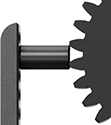
Slotted Spring Pins
 | |
End View |
Squeeze these pins into holes and they expand slightly, creating tension to hold parts in place. They are often used as hinge pins and as fasteners for springs and power transmission components. An alternative to dowel pins, they're lighter in weight with a hollow center and don’t need a precise hole. Also known as roll pins.
Spring Steel—These pins won't deform from stress and vibration. Although they're stronger than stainless steel, they're best for dry environments since moisture will cause them to rust.
Lg., mm | For Hole Dia., mm | Wall Thk., mm | Double Shear Breaking Strength, lbf | Min. Hardness | Specs. Met | Pkg. Qty. | Pkg. | |||
|---|---|---|---|---|---|---|---|---|---|---|
Spring Steel | ||||||||||
13 mm Diameter | ||||||||||
| 10 | 13 | 1.2 | 14,800 | Rockwell C42 | DIN 7346, ISO 13337 | 5 | 97161A261 | 000000 | ||
| 12 | 13 | 1.2 | 14,800 | Rockwell C42 | DIN 7346, ISO 13337 | 1 | 97161A262 | 0000 | ||
| 14 | 13 | 1.2 | 14,800 | Rockwell C42 | DIN 7346, ISO 13337 | 5 | 97161A263 | 00000 | ||
| 16 | 13 | 1.2 | 14,800 | Rockwell C42 | DIN 7346, ISO 13337 | 5 | 97161A264 | 0000 | ||
| 20 | 13 | 1.2 | 14,800 | Rockwell C42 | DIN 7346, ISO 13337 | 5 | 97161A265 | 00000 | ||
| 22 | 13 | 1.2 | 14,800 | Rockwell C42 | DIN 7346, ISO 13337 | 5 | 97161A266 | 00000 | ||
| 24 | 13 | 1.2 | 14,800 | Rockwell C42 | DIN 7346, ISO 13337 | 5 | 97161A267 | 00000 | ||
| 26 | 13 | 1.2 | 14,800 | Rockwell C42 | DIN 7346, ISO 13337 | 5 | 97161A268 | 00000 | ||
| 28 | 13 | 1.2 | 14,800 | Rockwell C42 | DIN 7346, ISO 13337 | 5 | 97161A269 | 00000 | ||
| 30 | 13 | 1.2 | 14,800 | Rockwell C42 | DIN 7346, ISO 13337 | 5 | 97161A270 | 00000 | ||
| 36 | 13 | 1.2 | 14,800 | Rockwell C42 | DIN 7346, ISO 13337 | 5 | 97161A271 | 00000 | ||
| 40 | 13 | 1.2 | 14,800 | Rockwell C42 | DIN 7346, ISO 13337 | 1 | 97161A272 | 0000 | ||
| 50 | 13 | 1.2 | 14,800 | Rockwell C42 | DIN 7346, ISO 13337 | 5 | 97161A273 | 00000 | ||
| 70 | 13 | 1.2 | 14,800 | Rockwell C42 | DIN 7346, ISO 13337 | 1 | 97161A274 | 0000 | ||
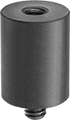
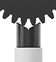
Fixturing for Parts Inspection
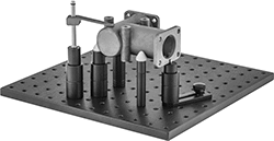 |
From towers and brackets to standoffs and supports, these components are the building blocks for your custom fixturing setup. They elevate parts so you can access a variety of angles for measuring and inspecting while protecting your measuring device from hitting the inspection table. You’ll often see them used with coordinate measuring machines (CMMs). They’re not for use in machining applications.