


Body Material Body Material |
|---|
|
Thread Type Thread Type |
|---|
For Use With For Use With | Show |
|---|
|
For Use With For Use With | Hide |
|---|
Handle Style Handle Style |
|---|
| Thumb Screw | |
Drive Style Drive Style |
|---|
System of Measurement System of Measurement |
|---|
|
Connection Style Connection Style |
|---|
 | Threaded |
Fitting Material Fitting Material |
|---|
|
Inlet Pipe Size Inlet Pipe Size |
|---|
Maximum Pressure Maximum Pressure |
|---|
|
Valve Operation Valve Operation |
|---|
|
Outlet Connection Type Outlet Connection Type |
|---|
 | Drain |
Gender Gender |
|---|
| Male | |
Environmental Rating Environmental Rating |
|---|
Valve Type Valve Type |
|---|
|
DFARS (Defense Acquisition Regulations Supplement) DFARS (Defense AcquisitionRegulations Supplement) |
|---|
Specifications Met Specifications Met |
|---|
|
RoHS (Restriction of Hazardous Substances) RoHS (Restriction ofHazardous Substances) |
|---|
|
REACH (Registration, Evaluation, Authorization and Restriction of Chemicals) REACH (Registration,Evaluation, Authorization and Restriction of Chemicals) |
|---|
|
How to Identify and Measure Fittings
Pipe size is an industry designation, not the actual size. View information about how to measure threaded and unthreaded pipe and pipe fittings.
More
About Noise, Filtration, and Flow Ratings
More
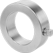
High-Pressure Steel Bleed Rings
- For Use With: Air, Natural Gas, Oil, Steam, Water
- Pressure Class: See table
- Flanges:
Pressure Class 300: Use Class 300 steel
Pressure Class 600: Use Class 600 steel
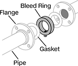
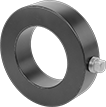
Tap into a pipe line to vent pressure, drain liquid, or take samples. These bleed rings act as a port where two pipe flanges meet, so you don’t have to disassemble your flanges to get inside. Remove the included plug for access or attach your own fitting, valve, or probe to the threaded hole. Made of black-coated steel, these bleed rings should be used in noncorrosive environments to prevent rusting.
Install these bleed rings between two pipe flanges along with a gasket on both sides to avoid leaks. They’re designed to fit flanges that meet ASME B16.5.
![]() For technical drawings and 3-D models, click on a part number.
For technical drawings and 3-D models, click on a part number.
Plug | Black-Coated Steel | |||||||||
|---|---|---|---|---|---|---|---|---|---|---|
| Pipe Size | OD | ID | Width | Wall Thickness | Maximum Pressure | Maximum Steam Pressure | Pipe Size | Thread Type | Each | |
Pressure Class 300 | ||||||||||
| 4 | 7" | 4.5" | 1.5" | 1.25" | 700 psi @ 72° F | 600 psi @ 300° F | 1/2 | NPT | 0000000 | 0000000 |
| 6 | 9 3/4" | 6.625" | 1.5" | 1.563" | 700 psi @ 72° F | 600 psi @ 300° F | 1/2 | NPT | 0000000 | 000000 |
Pressure Class 600 | ||||||||||
| 2 | 4 1/4" | 2.375" | 1.5" | 0.938" | 1,400 psi @ 72° F | 1,300 psi @ 300° F | 1/2 | NPT | 0000000 | 000000 |
| 3 | 5 3/4" | 3.5" | 1.5" | 1.125" | 1,400 psi @ 72° F | 1,300 psi @ 300° F | 1/2 | NPT | 0000000 | 000000 |
Low-Pressure Steel Bleed Rings

- For Use With: Air, Natural Gas, Oil, Steam, Water
- Pressure Class: 150
- Flanges: Use Class 125 or 150 steel
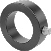
Access the inside of a pipe line to vent pressure, drain liquid, or take samples. These bleed rings act as a port where two pipe flanges meet, so you don’t have to disassemble your flanges to get inside. They include a plug, or you can attach your own fitting, valve, or probe. Made of black-coated steel, these bleed rings should be used in noncorrosive environments to prevent rusting.
Install these bleed rings between two pipe flanges along with a gasket on both sides to avoid leaks. They’re designed to fit flanges that meet ASME B16.5.
![]() For technical drawings and 3-D models, click on a part number.
For technical drawings and 3-D models, click on a part number.
Plug | Black-Coated Steel | |||||||||
|---|---|---|---|---|---|---|---|---|---|---|
| Pipe Size | OD | ID | Width | Wall Thickness | Maximum Pressure | Maximum Steam Pressure | Pipe Size | Thread Type | Each | |
| 2 | 4" | 2.375" | 1.5" | 0.813" | 285 psi @ 72° F | 230 psi @ 300° F | 1/2 | NPT | 0000000 | 0000000 |
| 3 | 5 1/4" | 3.5" | 1.5" | 0.875" | 285 psi @ 72° F | 230 psi @ 300° F | 1/2 | NPT | 0000000 | 000000 |
| 4 | 6 3/4" | 4.5" | 1.5" | 1.125" | 285 psi @ 72° F | 230 psi @ 300° F | 1/2 | NPT | 0000000 | 000000 |
| 6 | 8 5/8" | 6.625" | 1.5" | 1" | 285 psi @ 72° F | 230 psi @ 300° F | 1/2 | NPT | 0000000 | 000000 |
High-Pressure Stainless Steel Bleed Rings

- For Use With: Air, Natural Gas, Oil, Steam, Water
- Pressure Class: See table
- Flanges:
Pressure Class 300: Use Class 300 stainless steel
Pressure Class 600: Use Class 600 stainless steel
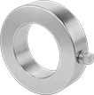
To relieve pressure, siphon liquid, or take samples in a pipe line where corrosion is a concern, these bleed rings act as a port between two pipe flanges. They have a threaded hole and plug to access the inside of your line instead of having to disassemble your flanges. Or remove the plug and attach your own fitting, valve, or probe. These bleed rings are stainless steel, so they resist rusting.
Install these bleed rings between two pipe flanges along with a gasket on both sides to avoid leaks. They’re designed to fit flanges that meet ASME B16.5.
304 stainless steel bleed rings keep corrosion at bay in wet conditions but will start to corrode when exposed to salt water. 316 stainless steel bleed rings withstand wet conditions as well as chemicals and salt water.
![]() For technical drawings and 3-D models, click on a part number.
For technical drawings and 3-D models, click on a part number.
Plug | ||||||||||
|---|---|---|---|---|---|---|---|---|---|---|
| Pipe Size | OD | ID | Width | Wall Thickness | Maximum Pressure | Maximum Steam Pressure | Pipe Size | Thread Type | Each | |
304/304L Stainless Steel | ||||||||||
Pressure Class 300 | ||||||||||
| 4 | 7" | 4.5" | 1.5" | 1.25" | 600 psi @ 72° F | 450 psi @ 300° F | 1/2 | NPT | 0000000 | 0000000 |
| 6 | 9 3/4" | 6.625" | 1.5" | 1.563" | 600 psi @ 72° F | 450 psi @ 300° F | 1/2 | NPT | 0000000 | 000000 |
Pressure Class 600 | ||||||||||
| 2 | 4 1/4" | 2.375" | 1.5" | 0.938" | 1,200 psi @ 72° F | 900 psi @ 300° F | 1/2 | NPT | 0000000 | 000000 |
| 3 | 5 3/4" | 3.5" | 1.5" | 1.125" | 1,200 psi @ 72° F | 900 psi @ 300° F | 1/2 | NPT | 0000000 | 000000 |
316/316L Stainless Steel | ||||||||||
Pressure Class 600 | ||||||||||
| 2 | 4 1/4" | 2.375" | 1.5" | 0.938" | 1,200 psi @ 72° F | 900 psi @ 300° F | 1/2 | NPT | 0000000 | 000000 |
| 3 | 5 3/4" | 3.5" | 1.5" | 1.125" | 1,200 psi @ 72° F | 900 psi @ 300° F | 1/2 | NPT | 0000000 | 000000 |
Low-Pressure Stainless Steel Bleed Rings

- For Use With: Air, Natural Gas, Oil, Steam, Water
- Pressure Class: 150
- Flanges: Use Class 125 or 150 stainless steel
Create an access point in a pipe line where corrosion is a concern. Often used to relieve pressure or siphon and sample liquids, these bleed rings act as a port between two pipe flanges, eliminating the need to take apart your flanges to get inside. They include a plug, or replace the plug with your own fitting, valve, or probe. Made of stainless steel, these bleed rings resist rusting.
Install these bleed rings between two pipe flanges along with a gasket on both sides to avoid leaks. They’re designed to fit flanges that meet ASME B16.5.
304 stainless steel bleed rings keep corrosion at bay in wet conditions but will start to corrode when exposed to salt water. 316 stainless steel bleed rings withstand wet conditions as well as chemicals and salt water.
![]() For technical drawings and 3-D models, click on a part number.
For technical drawings and 3-D models, click on a part number.
Plug | ||||||||||
|---|---|---|---|---|---|---|---|---|---|---|
| Pipe Size | OD | ID | Width | Wall Thickness | Maximum Pressure | Maximum Steam Pressure | Pipe Size | Thread Type | Each | |
304/304L Stainless Steel | ||||||||||
| 2 | 4" | 2.375" | 1.5" | 0.813" | 230 psi @ 72° F | 175 psi @ 300° F | 1/2 | NPT | 0000000 | 0000000 |
| 3 | 5 1/4" | 3.5" | 1.5" | 0.875" | 230 psi @ 72° F | 175 psi @ 300° F | 1/2 | NPT | 0000000 | 000000 |
| 4 | 6 3/4" | 4.5" | 1.5" | 1.125" | 230 psi @ 72° F | 175 psi @ 300° F | 1/2 | NPT | 0000000 | 000000 |
| 6 | 8 5/8" | 6.625" | 1.5" | 1" | 230 psi @ 72° F | 175 psi @ 300° F | 1/2 | NPT | 0000000 | 000000 |
316/316L Stainless Steel | ||||||||||
| 2 | 4" | 2.375" | 1.5" | 0.813" | 230 psi @ 72° F | 175 psi @ 300° F | 1/2 | NPT | 0000000 | 000000 |
| 3 | 5 1/4" | 3.5" | 1.5" | 0.875" | 230 psi @ 72° F | 175 psi @ 300° F | 1/2 | NPT | 0000000 | 000000 |
| 4 | 6 3/4" | 4.5" | 1.5" | 1.125" | 230 psi @ 72° F | 175 psi @ 300° F | 1/2 | NPT | 0000000 | 000000 |
| 6 | 8 5/8" | 6.625" | 1.5" | 1" | 230 psi @ 72° F | 175 psi @ 300° F | 1/2 | NPT | 0000000 | 000000 |
Drainage Valves
Also known as stop cocks, install these valves on your tank for easy draining.
Valves with external seal are for higher flow applications than valves with an internal seal.
Inlet | Outlet | ||||||||||
|---|---|---|---|---|---|---|---|---|---|---|---|
| Pipe Size | Thread Type | Gender | Connection Type | For Use With | Cable Lg., ft. | Max. Pressure | Temp. Range, °F | Ht. | Body Material | Each | |
Thumb-Screw Handle | |||||||||||
External Seal | |||||||||||
| 1/4 | NPT | Male | Unthreaded Hole | Air | __ | 250 psi @ 250° F | -40° to 250° | 1 1/8" | Brass | 0000000 | 00000 |
Cable Pull | |||||||||||
Internal Seal | |||||||||||
| 1/4 | NPT | Male | Unthreaded Hole | Air | 1 1/2 | 250 psi @ 250° F | -40° to 250° | 1 1/4" | Brass | 00000000 | 0000 |
| 1/4 | NPT | Male | Unthreaded Hole | Air | 3 | 250 psi @ 250° F | -40° to 250° | 1 1/4" | Brass | 00000000 | 0000 |
| 1/4 | NPT | Male | Unthreaded Hole | Air | 4 | 150 psi @ 250° F | -65° to 250° | 1 7/8" | Brass | 00000000 | 0000 |
| 1/4 | NPT | Male | Unthreaded Hole | Air | 5 | 250 psi @ 250° F | -40° to 250° | 1 1/4" | Brass | 00000000 | 0000 |
Self-Draining Breather Vents

Minimize moisture buildup in enclosures. Also known as drain plugs, these breather vents have a small outlet that allows condensation to drain. They have a silicone O-ring above the threads for a tight seal. Install them at the lowest point of the enclosure. Breather vents meet IP66 for protection in washdown environments. Use them to prevent excess vacuum and pressure in cylinders, gear boxes, and tanks and to block debris from entering equipment.
Brass breather vents have good corrosion resistance.
316 stainless steel breather vents have excellent corrosion resistance.
![]() For technical drawings and 3-D models, click on a part number.
For technical drawings and 3-D models, click on a part number.
| Pipe Size | Max. Temp., °F | Ht. | Dia. | For Use With | Environmental Rating | Each | |
NPT Male | |||||||
|---|---|---|---|---|---|---|---|
Brass Body and Fitting | |||||||
| 1/2 | 320° | 15/16" | 1" | Air | IEC Zone 1 Groups IIC, IIB, IIA, IEC Zone 21 Groups IIIC, IIIB, IIIA, IP66, NEMA 4X | 0000000 | 000000 |
| 1/4 | 320° | 15/16" | 11/16" | Air | IP66, NEMA 4X | 0000000 | 00000 |
316 Stainless Steel Body and Fitting | |||||||
| 1/2 | 320° | 15/16" | 1" | Air | IEC Zone 1 Groups IIC, IIB, IIA, IEC Zone 21 Groups IIIC, IIIB, IIIA, IP66, NEMA 4X | 0000000 | 00000 |
| 1/4 | 320° | 15/16" | 11/16" | Air | IP66, NEMA 4X | 0000000 | 00000 |