


About Duct Hose
More
About Duct Connections
More
Selecting Clamps Using Pipe, Conduit, or Tubing Trade Size
More
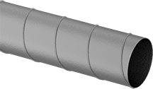
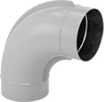
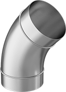
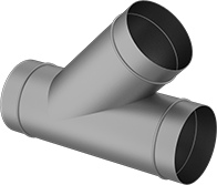
Crush-Resistant Spiral Duct and Fittings
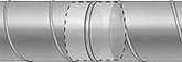
A spiral seam makes this duct strong and rigid. Fittings have male ends with a slightly smaller diameter to press-fit into duct.
PVC-coated steel combines the strength of steel with the corrosion resistance of plastic.
Add a noise reducer to duct to decrease noise by as much as 50%.
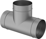
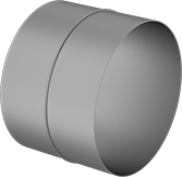
Male straight connectors are required to connect two pieces of duct.
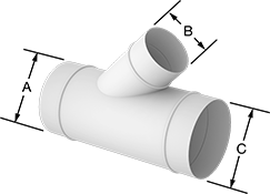
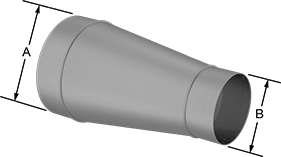
Reducers connect duct with different diameters.
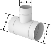
Duct Size | Male OD | PVC-Coated Steel | |||||
|---|---|---|---|---|---|---|---|
| (A) | (B) | (A) | (B) | End Construction | Gauge | Each | |
| 5 | 4 | 4 7/8" | 3 7/8" | Plain | 20 | 00000000 | 000000 |
| 6 | 4 | 5 7/8" | 3 7/8" | Plain | 20 | 00000000 | 00000 |
| 6 | 5 | 5 7/8" | 4 7/8" | Plain | 20 | 00000000 | 00000 |
| 7 | 6 | 6 7/8" | 5 7/8" | Plain | 20 | 00000000 | 00000 |
| 8 | 6 | 7 7/8" | 5 7/8" | Plain | 20 | 00000000 | 00000 |
| 8 | 7 | 7 7/8" | 6 7/8" | Plain | 20 | 00000000 | 00000 |
| 9 | 8 | 8 7/8" | 7 7/8" | Plain | 20 | 00000000 | 00000 |
| 10 | 8 | 9 7/8" | 7 7/8" | Plain | 20 | 00000000 | 000000 |
| 10 | 9 | 9 7/8" | 8 7/8" | Plain | 20 | 00000000 | 000000 |
| 12 | 10 | 11 7/8" | 9 7/8" | Plain | 20 | 00000000 | 000000 |
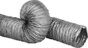
Economical Very Flexible Duct Hose for Fumes
- Very Flexible
- Compatible Clamps: Worm-Drive Clamps
- Color: Gray
- Temperature Range: -20° to 250° F
Hose has a single thin layer of PVC-coated fiberglass for venting smoke, water-based paint fumes, and welding fumes.
Warning: Hose should not be used for applications that generate a static charge.
Spiral | Per Ft. | |||||||||||||
|---|---|---|---|---|---|---|---|---|---|---|---|---|---|---|
| ID | OD | Bend Radius | Compresses To | Max. Vacuum | Max. Pressure | Material Thick. | Interior Surface Texture | Direction | Material | Specifications Met | Max. Continuous Lg., ft. | 1-24 | 25-Up | |
PVC-Coated Fiberglass | ||||||||||||||
| 4" | 4 1/4" | 1" | 20% | 0.5 in. of Hg @ 72° F | 5 psi @ 72° F | 0.005" | Ribbed | Right Hand | Metal | NFPA 90A, NFPA 90B, UL 181 Class 1 | 25 | 0000000 | 00000 | 00000 |
| 5" | 5 1/4" | 1 1/2" | 20% | 0.2 in. of Hg @ 72° F | 4 psi @ 72° F | 0.005" | Ribbed | Right Hand | Metal | NFPA 90A, NFPA 90B, UL 181 Class 1 | 25 | 0000000 | 0000 | 0000 |
| 6" | 6 3/16" | 1 1/2" | 20% | 0.1 in. of Hg @ 72° F | 3 psi @ 72° F | 0.005" | Ribbed | Right Hand | Metal | NFPA 90A, NFPA 90B, UL 181 Class 1 | 25 | 0000000 | 0000 | 0000 |
| 7" | 7 1/8" | 2" | 10% | 0.07 in. of Hg @ 72° F | 2 psi @ 72° F | 0.005" | Ribbed | Right Hand | Metal | NFPA 90A, NFPA 90B, UL 181 Class 1 | 25 | 0000000 | 0000 | 0000 |
| 8" | 8 1/8" | 2" | 10% | 0.05 in. of Hg @ 72° F | 2 psi @ 72° F | 0.005" | Ribbed | Right Hand | Metal | NFPA 90A, NFPA 90B, UL 181 Class 1 | 25 | 0000000 | 0000 | 0000 |
| 9" | 9 1/2" | 2 1/2" | 10% | 0.03 in. of Hg @ 72° F | 2 psi @ 72° F | 0.005" | Ribbed | Right Hand | Metal | NFPA 90A, NFPA 90B, UL 181 Class 1 | 25 | 0000000 | 00000 | 00000 |
| 10" | 10 1/4" | 2 1/2" | 10% | 0.02 in. of Hg @ 72° F | 1 psi @ 72° F | 0.005" | Ribbed | Right Hand | Metal | NFPA 90A, NFPA 90B, UL 181 Class 1 | 25 | 0000000 | 00000 | 00000 |
| 12" | 12 1/2" | 3" | 10% | 0.01 in. of Hg @ 72° F | 1 psi @ 72° F | 0.005" | Ribbed | Right Hand | Metal | NFPA 90A, NFPA 90B, UL 181 Class 1 | 25 | 0000000 | 00000 | 00000 |
| 14" | 14 1/2" | 3 1/2" | 10% | 0.01 in. of Hg @ 72° F | 1 psi @ 72° F | 0.005" | Ribbed | Right Hand | Metal | NFPA 90A, NFPA 90B, UL 181 Class 1 | 25 | 0000000 | 00000 | 00000 |
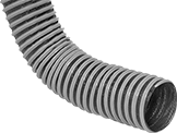
Blo-R-Vac Flexible Duct Hose with Wear Strip for Dust
- Flexible
- Compatible Clamps: Worm-Drive Clamps
- Color: Black; Wear Strip is Orange
- Temperature Range: -40° to 180° F
This general purpose hose for blowing and vacuum applications has a thick PVC wear strip that protects against damage caused by dragging. Hose is for use with lint, dust, and sawdust. It meets UL 94 HB and UL 94 V-0 for flame retardance.
Warning: Hose should not be used for applications that generate a static charge.
Spiral | Per Ft. | |||||||||||||
|---|---|---|---|---|---|---|---|---|---|---|---|---|---|---|
| ID | OD | Bend Radius | Compresses To | Max. Vacuum | Max. Pressure | Material Thick. | Interior Surface Texture | Direction | Material | Specifications Met | Max. Continuous Lg., ft. | 1-24 | 25-Up | |
PVC-Coated Polyester | ||||||||||||||
| 3" | 3 3/8" | 1 1/2" | 85% | 24 in. of Hg @ 72° F | 28 psi @ 72° F | 0.03" | Ribbed | Right Hand | Metal | UL 94 HB, UL 94 V-0 | 25 | 00000000 | 00000 | 00000 |
| 3 1/2" | 3 7/8" | 1 1/2" | 85% | 22 in. of Hg @ 72° F | 26 psi @ 72° F | 0.03" | Ribbed | Right Hand | Metal | UL 94 HB, UL 94 V-0 | 25 | 0000000 | 0000 | 00 |
Per Ft. | ||||||||||||||
| 1-24 | 25-Up | |||||||||||||
| 4" | 4 3/8" | 2" | 75% | 18 in. of Hg @ 72° F | 24 psi @ 72° F | 0.03" | Ribbed | Right Hand | Metal | UL 94 HB, UL 94 V-0 | 25 | 00000000 | 00000 | 0000 |
| 5" | 5 3/8" | 2 1/2" | 75% | 16 in. of Hg @ 72° F | 20 psi @ 72° F | 0.03" | Ribbed | Right Hand | Metal | UL 94 HB, UL 94 V-0 | 25 | 00000000 | 00000 | 0000 |
| 6" | 6 7/16" | 3" | 50% | 17 in. of Hg @ 72° F | 18 psi @ 72° F | 0.03" | Ribbed | Right Hand | Metal | UL 94 HB, UL 94 V-0 | 25 | 00000000 | 00000 | 0000 |
| 7" | 7 5/8" | 3 1/2" | 70% | 10 in. of Hg @ 72° F | 15 psi @ 72° F | 0.03" | Ribbed | Right Hand | Metal | UL 94 HB, UL 94 V-0 | 25 | 0000000 | 00000 | 00 |
Per Ft. | ||||||||||||||
| 1-24 | 25-Up | |||||||||||||
| 8" | 8 7/16" | 4" | 50% | 8 in. of Hg @ 72° F | 12 psi @ 72° F | 0.03" | Ribbed | Right Hand | Metal | UL 94 HB, UL 94 V-0 | 25 | 00000000 | 00000 | 00000 |
| 10" | 10 7/16" | 5" | 50% | 5 in. of Hg @ 72° F | 8 psi @ 72° F | 0.03" | Ribbed | Right Hand | Metal | UL 94 HB, UL 94 V-0 | 25 | 00000000 | 00000 | 00000 |
| 12" | 12 7/16" | 6" | 50% | 3 in. of Hg @ 72° F | 6 psi @ 72° F | 0.03" | Ribbed | Right Hand | Metal | UL 94 HB, UL 94 V-0 | 25 | 00000000 | 00000 | 00000 |
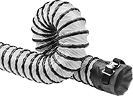
Quick-Attach Duct Hose with Wear Strip for Air
- Very Flexible
- Color: Yellow; Wear Strip is Black
- Temperature Range: -20° to 180° F
The ends of this hose have a belt-and-buckle connection that eliminates the need for clamps. To connect hose, slip a duct hose connector into one end and cinch the belt for a secure hold. Hose has a wear strip that protects against damage caused by dragging. Hose meets UL 94 V-0 for flame retardance.
Spiral | ||||||||||||||
|---|---|---|---|---|---|---|---|---|---|---|---|---|---|---|
| ID | OD | Bend Radius | Compresses To | Max. Vacuum | Max. Pressure | Material Thick. | Direction | Material | Specifications Met | 5 ft. | 10 ft. | 15 ft. | 25 ft. | |
PVC-Coated Polyester | ||||||||||||||
| 4" | 4 3/8" | 2" | 10% | 9 in. of Hg @ 72° F | 13 psi @ 72° F | 0.014" | Right Hand | Metal | NFPA 701, UL 94 V-0 | 0000000 | ||||
| 5" | 5 3/8" | 3 1/2" | 10% | 7 in. of Hg @ 72° F | 12 psi @ 72° F | 0.014" | Right Hand | Metal | NFPA 701, UL 94 V-0 | 0000000 | ||||
| 6" | 6 7/16" | 3" | 10% | 3.5 in. of Hg @ 72° F | 11 psi @ 72° F | 0.014" | Right Hand | Metal | NFPA 701, UL 94 V-0 | 0000000 | ||||
| 8" | 8 1/2" | 4 1/2" | 10% | 2.8 in. of Hg @ 72° F | 8 psi @ 72° F | 0.014" | Right Hand | Metal | NFPA 701, UL 94 V-0 | 0000000 | ||||
| 10" | 10 9/16" | 5 1/2" | 10% | 2 in. of Hg @ 72° F | 7 psi @ 72° F | 0.014" | Right Hand | Metal | NFPA 701, UL 94 V-0 | 0000000 | ||||
| 12" | 12 9/16" | 7" | 10% | 1 in. of Hg @ 72° F | 5 psi @ 72° F | 0.014" | Right Hand | Metal | NFPA 701, UL 94 V-0 | 0000000 | ||||
| 16" | 16 9/16" | 9 1/2" | 10% | 0.5 in. of Hg @ 72° F | 5 psi @ 72° F | 0.014" | Right Hand | Metal | NFPA 701, UL 94 V-0 | 0000000 | ||||
| 18" | 18 9/16" | 10" | 10% | 0.4 in. of Hg @ 72° F | 4 psi @ 72° F | 0.014" | Right Hand | Metal | NFPA 701, UL 94 V-0 | 0000000 | ||||
| 20" | 20 9/16" | 11" | 10% | 0.3 in. of Hg @ 72° F | 3 psi @ 72° F | 0.014" | Right Hand | Metal | NFPA 701, UL 94 V-0 | 0000000 | ||||
| 24" | 24 5/8" | 13 1/2" | 10% | 0.1 in. of Hg @ 72° F | 2 psi @ 72° F | 0.014" | Right Hand | Metal | NFPA 701, UL 94 V-0 | 0000000 | ||||
Swivel Threaded-Rod-Mount Loop Hangers
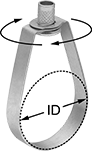
These hangers have a swivel nut for adjusting direction after mounting. They're also known as teardrop hangers. Combine with a threaded rod or other fastener to hang from the ceiling. To mount, screw threaded rod into the threaded hole on top of the hanger. The hanging height can be adjusted after material is installed. PVC-coated steel hangers reduce wear on material.
ID | ||||||||||||||
|---|---|---|---|---|---|---|---|---|---|---|---|---|---|---|
| Inch | Metric, mm | For Pipe Size | For Thread Size | Color | Cap., lbs. | Lg. | Wd. | Ht. | Thick. | Temp. Range, °F | Specifications Met | Pkg. Qty. | Pkg. | |
PVC-Coated Steel | ||||||||||||||
| 13/16" | 21 | 1/2 | 3/8"-16 | Black | 610 | 15/16" | 5/8" | 2 5/16" | 1/16" | -30° to 200° | Fed. Spec. WW-H-171E, Type 10 MSS-SP-58-2009, Type 10 | 1 | 0000000 | 00000 |
| 1 1/16" | 27 | 3/4 | 3/8"-16 | Black | 610 | 1 3/16" | 5/8" | 2 5/8" | 1/16" | -30° to 200° | Fed. Spec. WW-H-171E, Type 10 MSS-SP-58-2009, Type 10 | 1 | 0000000 | 00000 |
| 1 5/16" | 33 | 1 | 3/8"-16 | Black | 610 | 1 7/16" | 5/8" | 2 7/8" | 1/16" | -30° to 200° | Fed. Spec. WW-H-171E, Type 10 MSS-SP-58-2009, Type 10 | 1 | 0000000 | 00000 |
| 1 11/16" | 43 | 1 1/4 | 3/8"-16 | Black | 610 | 1 13/16" | 5/8" | 3 7/16" | 1/16" | -30° to 200° | Fed. Spec. WW-H-171E, Type 10 MSS-SP-58-2009, Type 10 | 1 | 0000000 | 00000 |
| 1 7/8" | 48 | 1 1/2 | 3/8"-16 | Black | 610 | 2" | 5/8" | 3 11/16" | 1/16" | -30° to 200° | Fed. Spec. WW-H-171E, Type 10 MSS-SP-58-2009, Type 10 | 1 | 0000000 | 00000 |
| 2 3/8" | 60 | 2 | 3/8"-16 | Black | 610 | 2 1/2" | 5/8" | 4 3/16" | 1/8" | -30° to 200° | Fed. Spec. WW-H-171E, Type 10 MSS-SP-58-2009, Type 10 | 1 | 0000000 | 00000 |
| 2 7/8" | 73 | 2 1/2 | 1/2"-13 | Black | 970 | 3 1/16" | 3/4" | 5 5/16" | 1/8" | -30° to 200° | Fed. Spec. WW-H-171E, Type 10 MSS-SP-58-2009, Type 10 | 1 | 0000000 | 00000 |
| 3 1/2" | 89 | 3 | 1/2"-13 | Black | 970 | 3 11/16" | 3/4" | 6" | 1/8" | -30° to 200° | Fed. Spec. WW-H-171E, Type 10 MSS-SP-58-2009, Type 10 | 1 | 0000000 | 00000 |
| 4" | 102 | 3 1/2 | 1/2"-13 | Black | 970 | 4 3/16" | 3/4" | 6 1/2" | 1/8" | -30° to 200° | Fed. Spec. WW-H-171E, Type 10 MSS-SP-58-2009, Type 10 | 1 | 0000000 | 00000 |
| 4 1/2" | 114 | 4 | 5/8"-11 | Black | 1,250 | 4 3/4" | 3/4" | 7 1/8" | 1/8" | -30° to 200° | Fed. Spec. WW-H-171E, Type 10 MSS-SP-58-2009, Type 10 | 1 | 0000000 | 00000 |