


Maximum Torque Maximum Torque |
|---|
Maximum Speed Maximum Speed |
|---|
|
OD OD |
|---|
|
|
|
Torque Adjustability Torque Adjustability |
|---|
|
Minimum Torque Minimum Torque |
|---|
|
|
Overall Length Overall Length |
|---|
|
|
|
Torque-Limiting Mechanism Torque-Limiting Mechanism |
|---|
|
Torque-Limiting Direction Torque-Limiting Direction |
|---|
|
DFARS (Defense Acquisition Regulations Supplement) DFARS (Defense AcquisitionRegulations Supplement) |
|---|
RoHS (Restriction of Hazardous Substances) RoHS (Restriction ofHazardous Substances) |
|---|
|
Shaft Mount Type Shaft Mount Type |
|---|
|


Magnetic Torque-Limiting Shaft-to-Gear Couplings

Also known as hysteresis clutches, these couplings use magnetic force to brake, control tension, and prevent torque overload. They have few moving parts, so they last longer than mechanical couplings. Twist the adjustment ring to set the torque within the range listed, then lock the ring in place with the included set screw.
![]() For technical drawings and 3-D models, click on a part number.
For technical drawings and 3-D models, click on a part number.
Torque, in.-lbs | Mounting Hole | |||||||||
|---|---|---|---|---|---|---|---|---|---|---|
| Min. | Max. | Max. Speed, rpm | OD | Overall Lg. | Torque-Limiting Direction | Thread Size | Thread Pitch, mm | For Shaft Dia. | Each | |
| 0.06 | 1.25 | 880 | 1 15/16" | 1 5/8" | Clockwise and Counterclockwise | M4 | 0.7 | 1/4" | 000000 | 0000000 |
| 0.18 | 5 | 300 | 2 3/4" | 2 7/16" | Clockwise and Counterclockwise | M4 | 0.7 | 3/8" | 000000 | 000000 |
| 0.5 | 10.6 | 220 | 3 5/16" | 2 1/2" | Clockwise and Counterclockwise | M5 | 0.8 | 000000 | 000000 | |
| 1 | 25 | 250 | 4 11/16" | 3 1/8" | Clockwise and Counterclockwise | M5 | 0.8 | 000000 | 000000 | |
| 2 | 50 | 200 | 5 1/4" | 3 1/8" | Clockwise and Counterclockwise | M5 | 0.8 | 000000 | 000000 | |
| 3 | 70 | 200 | 6 5/16" | 4 1/8" | Clockwise and Counterclockwise | 1/4"-20 | __ | 000000 | 00000000 | |
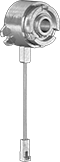
Magnetic Torque-Limiting Shaft-to-Gear Couplings with Shaft

Also known as hysteresis clutches, these couplings use magnetic force to brake, control tension, and prevent torque overload. They have few moving parts, so they last longer than mechanical couplings. Twist the adjustment ring to set the torque within the range listed, then lock the ring in place with the included set screw.
![]() For technical drawings and 3-D models, click on a part number.
For technical drawings and 3-D models, click on a part number.
Torque, in.-lbs. | Mounting Hole | ||||||||||
|---|---|---|---|---|---|---|---|---|---|---|---|
| Shaft Dia. | Min. | Max. | Max. Speed, rpm | OD | Overall Lg. | Shaft Type | Torque-Limiting Direction | Thread Size | Thread Pitch, mm | Each | |
| 3/16" | 0.01 | 0.06 | 2,000 | 1" | 1 3/8" | D-Profile | Clockwise and Counterclockwise | M3 | 0.5 | 0000000 | 0000000 |
| 3/16" | 0.01 | 0.13 | 1,500 | 1" | 1 3/8" | D-Profile | Clockwise and Counterclockwise | M3 | 0.5 | 0000000 | 000000 |
| 5/16" | 0.03 | 0.44 | 1,050 | 1 7/16" | 1 3/4" | D-Profile | Clockwise and Counterclockwise | M3 | 0.5 | 0000000 | 000000 |
Electromagnetic Torque-Limiting Shaft-to-Gear Couplings
Use these with an overload sensor in an automated system to instantly disconnect power and prevent damage. Couplings also accelerate loads from zero to full speed in less than three milliseconds when the power is turned on.
Clockwise Torque-Limiting Direction | Counterclockwise Torque-Limiting Direction | ||||||||||
|---|---|---|---|---|---|---|---|---|---|---|---|
| For Shaft Dia. | Max. Torque, in.-lbs. | Max. Speed, rpm | OD | Overall Lg. | Electrical Connection Type | Wire Lead Lg. | Voltage | Each | Each | ||
| 1/4" | 30 | 1,400 | 1 1/4" | 1 1/8" | Hardwire | 15" | 24V DC | 0000000 | 000000 | 0000000 | 000000 |
| 5/16" | 30 | 1,400 | 1 1/4" | 1 1/8" | Hardwire | 15" | 24V DC | 0000000 | 00000 | 0000000 | 00000 |
| 3/8" | 75 | 1,400 | 1 3/4" | 1 1/2" | Hardwire | 18" | 24V DC | 0000000 | 000000 | 0000000 | 000000 |
| 1/2" | 75 | 1,400 | 1 3/4" | 1 1/2" | Hardwire | 18" | 24V DC | 0000000 | 000000 | 0000000 | 000000 |
Electromagnetic Tensioning, Holding, and Stopping Shaft-to-Gear Couplings

Also known as electric hysteresis brakes, these couplings use magnetic force to create drag to slow or stop the motion of your drive system. Use them with a current-limiting transformer to adjust the electrical current, which controls the amount of torque applied.
![]() For technical drawings and 3-D models, click on a part number.
For technical drawings and 3-D models, click on a part number.
Keyway | Mounting Hole | ||||||||||||||
|---|---|---|---|---|---|---|---|---|---|---|---|---|---|---|---|
| Shaft Dia. | Max. Torque, in.-lbs. | Max. Speed, rpm | OD | Overall Lg. | Shaft Type | Wd. | Dp. | Torque-Limiting Direction | Electrical Connection Type | Wire Lead Lg. | Voltage | Thread Size | Thread Pitch, mm | Each | |
| 0.118" | 0.2 | 1,990 | 1 1/4" | 1 5/8" | Round | __ | __ | Clockwise and Counterclockwise | Hardwire | 18" | 24V DC | M2.5 | 4 | 0000000 | 0000000 |
| 0.197" | 0.8 | 1,200 | 1 13/16" | 2" | D-Profile | __ | __ | Clockwise and Counterclockwise | Hardwire | 18" | 24V DC | M2.5 | 5 | 0000000 | 000000 |
| 0.197" | 1.3 | 760 | 2" | 2 1/8" | D-Profile | __ | __ | Clockwise and Counterclockwise | Hardwire | 18" | 24V DC | M3 | 6 | 0000000 | 000000 |
| 0.276" | 3.5 | 570 | 2 3/8" | 3" | D-Profile | __ | __ | Clockwise and Counterclockwise | Hardwire | 18" | 24V DC | M4 | 8 | 0000000 | 000000 |
| 0.394" | 11 | 590 | 3 5/8" | 4" | D-Profile | __ | __ | Clockwise and Counterclockwise | Hardwire | 18" | 24V DC | M4 | 9 | 0000000 | 000000 |
| 0.472" | 19 | 500 | 4 7/16" | 4 7/8" | Keyed | 5/32" | 3/32" | Clockwise and Counterclockwise | Hardwire | 18" | 24V DC | M5 | 10 | 0000000 | 000000 |
| 0.591" | 32 | 420 | 5 7/16" | 5 1/8" | Keyed | 3/16" | 1/8" | Clockwise and Counterclockwise | Hardwire | 18" | 24V DC | M5 | 10 | 0000000 | 00000000 |