Filter by
Mount Type
Material
Thread Size
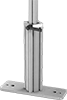
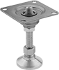
Mounting Foot Type


Width

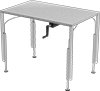
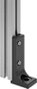
T-Slotted Framing Component

Performance


Export Control Classification Number (ECCN)
DFARS Specialty Metals
Hardness Rating
Building and Machinery Hardware
Material Handling
Fabricating and Machining
Power Transmission