


Filter by
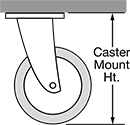
For Caster Mount Height


Material
Brake Extension Pedal Location
Mounting Location
Brake Retraction Pedal Location
Color
DFARS Specialty Metals
Export Control Classification Number (ECCN)
Finish
REACH
RoHS
Floor Locks
Mounting Plate Style 1
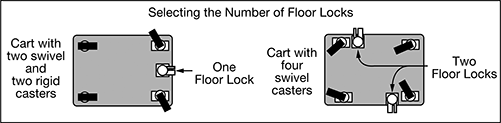
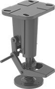
Stabilize carts, trucks, workbenches, and other mobile equipment during loading and unloading. Floor locks bolt or weld to the underside of your equipment and have a spring-loaded base with a nonskid floor pad to keep equipment stationary.
Note: Floor locks are not load rated. They are designed to brake your equipment in place, not lift it off the floor.
Pivoting base compensates for uneven floors.
Retraction Pedal on Both Sides with Pivoting Base
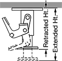
Mounting Plate Style 1
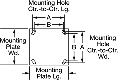
Ht. | Mounting Plate | Mounting Hole Ctr.-to-Ctr. | |||||||||||||
|---|---|---|---|---|---|---|---|---|---|---|---|---|---|---|---|
| For Caster Mount Ht. | Extended | Retracted | Clearance | Style | Lg. | Wd. | Lg. (A) | Lg. (B) | Wd. (A) | Wd. (B) | Mounting Fasteners Included | For Screw Size | Color | Each | |
Painted Iron | |||||||||||||||
| 5 5/8"-5 7/8" | 5 5/8" | 4 9/16" | 1 5/16" | 1 | 4 13/16" | 4 1/4" | 3 5/8" | 3" | 3" | 2 5/8" | No | 3/8" | Gray | 00000000 | 0000000 |
| 7 1/4"-7 1/2" | 7 1/2" | 6" | 1 3/4" | 1 | 6 1/2" | 4 3/4" | 5 1/4" | 4 15/16" | 3 3/8" | 2 7/16" | No | 1/2" | Gray | 00000000 | 000000 |
| 10 1/4"-10 5/8" | 10 1/4" | 9 1/8" | 1 3/8" | 1 | 6 1/2" | 4 3/4" | 5 1/4" | 4 15/16" | 3 3/8" | 2 7/16" | No | 1/2" | Gray | 00000000 | 000000 |