


Measure your pipe and fittings to identify their pipe size, thread size, schedule, and thread type. Then, find compatible components.
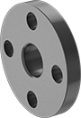
Low-Pressure Iron and Steel Unthreaded Pipe Flanges
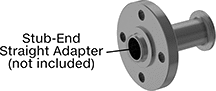 |
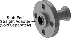
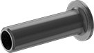
Stub-End Flange with Straight Adapter: Front |
 |  |  |  |  |  |  |
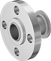
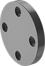
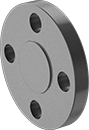
Butt Weld: Front | Butt Weld: Raised Surface on Back | Slip-On Weld: Front | Slip-On Weld: Raised Surface on Back | Socket Connect: Front | Socket Connect: Raised Surface on Back | Stub End: Flat Surface on Back |
Pipe Size | Bolt Hole | ||||||||||||||
|---|---|---|---|---|---|---|---|---|---|---|---|---|---|---|---|
(A) | (B) | Flanged Connection Surface (B) | Flange OD | For Bolt Dia. | Dia. | No. Of | Bolt Circle Dia. | Pressure Class | Material | Max. Pressure @ Temp. | Max. Steam Pressure @ Temp. | Each | |||
Butt Weld | |||||||||||||||
| 5 | 5 | Raised | 10" | 3/4" | 7/8" | 8 | 8 1/2" | 150 | Steel | 285 psi @ 72° F | 150 psi @ 300° F | 68095K413 | 000000 | ||
Slip-On Weld Female | |||||||||||||||
| 5 | 5 | Raised | 10" | 3/4" | 7/8" | 8 | 8 1/2" | 150 | Steel | 285 psi @ 72° F | 150 psi @ 300° F | 68095K396 | 00000 | ||
Socket-Connect Female | |||||||||||||||
| 5 | 5 | Raised | 10" | 3/4" | 7/8" | 8 | 8 1/2" | 150 | Steel | 285 psi @ 72° F | 150 psi @ 300° F | 68095K399 | 00000 | ||
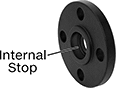
Stub-End Female | |||||||||||||||
| 5 | 5 | Flat | 10" | 3/4" | 7/8" | 8 | 8 1/2" | 150 | Steel | 285 psi @ 72° F | 150 psi @ 300° F | 68095K419 | 00000 | ||
 |  |
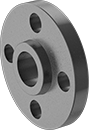
Front | Raised Surface on Back |
Bolt Hole | ||||||||||||||
|---|---|---|---|---|---|---|---|---|---|---|---|---|---|---|
Pipe Size | Flanged Connection Surface | Flange OD | For Bolt Dia. | Dia. | No. Of | Bolt Circle Dia. | Pressure Class | Material | Max. Pressure @ Temp. | Max. Steam Pressure @ Temp. | Each | |||
Flanged | ||||||||||||||
| 5 | Raised | 10" | 3/4" | 7/8" | 8 | 8 1/2" | 150 | Steel | 285 psi @ 72° F | 150 psi @ 300° F | 68095K416 | 000000 | ||
High-Pressure Stainless Steel Unthreaded Pipe Flanges
 |
Stub End with Straight Adapter (Front) |
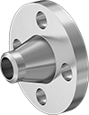 | 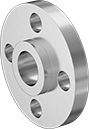 |  |
Butt Weld | Slip-On | Socket-Connect |
Pipe Size | Dash Size | Bolt Hole | 304/304L Stainless Steel | 316/316L Stainless Steel | ||||||||||||||
|---|---|---|---|---|---|---|---|---|---|---|---|---|---|---|---|---|---|---|
(A) | (B) | (A) | (B) | Flanged Connection Surface (B) | Flange OD | For Bolt Dia. | Dia. | No. Of | Bolt Circle Dia. | Pressure Class | Max. Pressure @ Temp. | Max. Steam Pressure @ Temp. | Each | Each | ||||
Butt Weld | ||||||||||||||||||
| 4 | 4 | 64 | 64 | Raised | 10" | 3/4" | 0.875" | 8 | 7 7/8" | 300 | 600 psi @ 72° F | 415 psi @ 360° F | 4448T295 | 0000000 | 4452T315 | 0000000 | ||
Slip-On Weld Female | ||||||||||||||||||
| 4 | 4 | 64 | 64 | Raised | 10" | 3/4" | 0.875" | 8 | 7 7/8" | 300 | 600 psi @ 72° F | 300 psi @ 360° F | 4448T259 | 000000 | 4452T269 | 000000 | ||
Socket-Connect Female | ||||||||||||||||||
| 4 | 4 | 64 | 64 | Raised | 10" | 3/4" | 0.875" | 8 | 7 7/8" | 300 | 600 psi @ 72° F | 300 psi @ 360° F | 4448T273 | 000000 | 4452T283 | 000000 | ||
Stub End | ||||||||||||||||||
| 4 | 4 | 64 | 64 | Flat | 10" | 3/4" | 0.875" | 8 | 7 7/8" | 300 | 600 psi @ 72° F | 300 psi @ 360° F | 4448T262 | 000000 | ——— | 0 | ||
 |  |
Front | Raised Surface on Back |
Bolt Hole | 304/304L Stainless Steel | 316/316L Stainless Steel | ||||||||||||||
|---|---|---|---|---|---|---|---|---|---|---|---|---|---|---|---|---|
Pipe Size | Dash Size | Flanged Connection Surface | Flange OD | For Bolt Dia. | Dia. | No. Of | Bolt Circle Dia. | Pressure Class | Max. Pressure @ Temp. | Max. Steam Pressure @ Temp. | Each | Each | ||||
Flanged | ||||||||||||||||
| 4 | 64 | Raised | 10" | 3/4" | 0.875" | 8 | 7 7/8" | 300 | 600 psi @ 72° F | 300 psi @ 360° F | 4448T284 | 0000000 | 4452T294 | 0000000 | ||
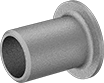 |
Straight Adapter |
304/304L Stainless Steel | |||||||
|---|---|---|---|---|---|---|---|
Pipe Size | Wall Thk. | Flange OD | Construction | Pipe Schedule | Each | ||
| 4 | 0.237" | 6 3/16" | Welded | 40 | 45605K663 | 000000 | |
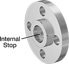
High-Pressure Iron and Steel Unthreaded Pipe Flanges
 |  |  |  |
Butt Weld (Front) | Butt Weld (Raised Surface on Back) | Slip-On Weld (Front) | Slip-On Weld (Raised Surface on Back) |
 |  |  |  |
Socket Connect (Front) | Socket-Connect (Raised Surface on Back) | Stub-End (Front) | Stub-End (Flat Surface on Back) |
Pipe Size | Dash Size | Bolt Hole | |||||||||||||||
|---|---|---|---|---|---|---|---|---|---|---|---|---|---|---|---|---|---|
(A) | (B) | (A) | (B) | Flanged Connection Surface (B) | Flange OD | For Bolt Dia. | Dia. | No. Of | Bolt Circle Dia. | Pressure Class | Material | Max. Pressure @ Temp. | Max. Steam Pressure @ Temp. | Each | |||
Butt Weld | |||||||||||||||||
| 4 | 4 | 64 | 64 | Raised | 10" | 3/4" | 7/8" | 8 | 7 7/8" | 300 | Steel | 600 psi @ 72° F | 300 psi @ 300° F | 6806K315 | 000000 | ||
Slip-On Weld Female | |||||||||||||||||
| 4 | 4 | 64 | 64 | Raised | 10" | 3/4" | 7/8" | 8 | 7 7/8" | 300 | Steel | 600 psi @ 72° F | 300 psi @ 300° F | 6806K285 | 00000 | ||
Socket-Connect Female | |||||||||||||||||
| 4 | 4 | 64 | 64 | Raised | 10" | 3/4" | 7/8" | 8 | 7 7/8" | 300 | Steel | Not Rated | Not Rated | 6806K295 | 000000 | ||
Stub-End Female | |||||||||||||||||
| 4 | 4 | 64 | 64 | Flat | 10" | 3/4" | 7/8" | 8 | 7 7/8" | 300 | Steel | 600 psi @ 72° F | 300 psi @ 300° F | 6806K335 | 00000 | ||
 |  |
Front | Raised Surface on Back |
Bolt Hole | |||||||||||||||
|---|---|---|---|---|---|---|---|---|---|---|---|---|---|---|---|
Pipe Size | Dash Size | Flanged Connection Surface | Flange OD | For Bolt Dia. | Dia. | No. Of | Bolt Circle Dia. | Pressure Class | Material | Max. Pressure @ Temp. | Max. Steam Pressure @ Temp. | Each | |||
Flanged | |||||||||||||||
| 4 | 64 | Raised | 10" | 3/4" | 7/8" | 8 | 7 7/8" | 300 | Steel | 600 psi @ 72° F | 300 psi @ 300° F | 6806K325 | 000000 | ||
 |
Straight Adapter |
Pipe Size | Flange OD | Construction | Pipe Schedule | Finished Material | Each | ||
|---|---|---|---|---|---|---|---|
| 4 | 6 3/16" | Seamless | 80 | Steel | 4981T291 | 0000000 |
High-Pressure Stainless Steel Threaded Pipe Flanges
 |  |
Front | Raised Surface on Back |
Pipe Size | Dash Size | Bolt Hole | 304/304L Stainless Steel | 316/316L Stainless Steel | ||||||||||||||
|---|---|---|---|---|---|---|---|---|---|---|---|---|---|---|---|---|---|---|
(A) | (B) | (A) | (B) | Flanged Connection Surface (B) | Flange OD | For Bolt Dia. | Dia. | No. Of | Bolt Circle Dia. | Pressure Class | Max. Pressure @ Temp. | Max. Steam Pressure @ Temp. | Each | Each | ||||
NPT Female | ||||||||||||||||||
| 4 | 4 | 64 | 64 | Raised | 10" | 3/4" | 0.875" | 8 | 7 7/8" | 300 | 600 psi @ 72° F | 300 psi @ 300° F | 7977K19 | 0000000 | 7469T39 | 0000000 | ||
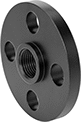
High-Pressure Iron and Steel Threaded Pipe Flanges
 |  |
Front | Raised Surface on Back |
Pipe Size | Bolt Hole | ||||||||||||||
|---|---|---|---|---|---|---|---|---|---|---|---|---|---|---|---|
(A) | (B) | Flanged Connection Surface (B) | Flange OD | For Bolt Dia. | Dia. | No. Of | Bolt Circle Dia. | Pressure Class | Material | Max. Pressure @ Temp. | Max. Steam Pressure @ Temp. | Each | |||
NPT Female | |||||||||||||||
| 4 | 4 | Raised | 10" | 3/4" | 7/8" | 8 | 7 7/8" | 300 | Steel | 600 psi @ 72° F | 300 psi @ 300° F | 6806K128 | 000000 | ||
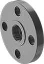
Low-Pressure Iron and Steel Threaded Pipe Flanges
 |  |
Front | Raised Surface on Back |
Pipe Size | Bolt Hole | ||||||||||||||
|---|---|---|---|---|---|---|---|---|---|---|---|---|---|---|---|
(A) | (B) | Flanged Connection Surface (B) | Flange OD | For Bolt Dia. | Dia. | No. Of | Bolt Circle Dia. | Pressure Class | Material | Max. Pressure @ Temp. | Max. Steam Pressure @ Temp. | Each | |||
NPT Female | |||||||||||||||
| 5 | 5 | Raised | 10" | 3/4" | 7/8" | 8 | 8 1/2" | 150 | Steel | 285 psi @ 72° F | 230 psi @ 300° F | 68095K222 | 000000 | ||
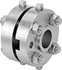
Flange Unions
%20--%3e%3cg%3e%3cg%20id='Layer_1'%3e%3cpath%20class='cls-1'%20d='M68,27.2c-14.6,0-26.4,11.7-26.4,26.3,0,7,2.8,13.7,7.7,18.7v44.8l18.8-16.1,18.7,16.1v-44.9c10.3-10.3,10.3-27,0-37.3-5-4.9-11.7-7.7-18.7-7.7h0ZM81.3,105l-13.2-11.4-13.2,11.4v-28.7c8.2,4.8,18.3,4.8,26.5,0v28.7ZM76.2,70.8c-5.2,2.5-11.2,2.5-16.4,0-9.5-4.5-13.5-15.9-9-25.4,4.5-9.5,15.9-13.5,25.4-9,9.5,4.5,13.5,15.9,9,25.4-1.9,4-5.1,7.1-9,9Z'/%3e%3cpath%20class='cls-2'%20d='M5.8,95.5c-1.2,0-2.1-1-2.1-2.1,0,0,0,0,0,0V29.4h20.9c2.1,0,3.8-1.7,3.8-3.8V3.7c.2,0,.4,0,.5,0h37.5c1.2,0,2.1,1,2.1,2.1v18.6c1.2,0,2.5.1,3.7.3V5.8C72.2,2.6,69.6,0,66.4,0H28.9c-1.5,0-3,.6-4.1,1.7h-.1c0,.1-23,23.2-23,23.2-1.1,1.1-1.7,2.6-1.7,4.1v64.3c0,3.2,2.6,5.8,5.8,5.8h41.7v-3.7H5.8ZM24.7,7.1v18.7H6L24.7,7.1Z'/%3e%3c/g%3e%3c/g%3e%3c/svg%3e)
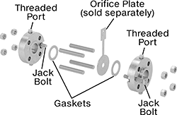
 | 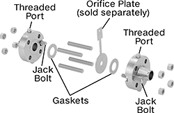 |
Assembled | Exploded |
Bolt Hole | Port | For Carbon Steel Fittings | For 316/316L Stainless Steel Fittings | |||||||||||||||||
|---|---|---|---|---|---|---|---|---|---|---|---|---|---|---|---|---|---|---|---|---|
Pipe Size | Construction | Flange OD | For Bolt Dia. | Dia. | No. of | Bolt Circle Dia. | Pipe Size | No. of | Includes | Specs. Met | For Use With | Temp. | Pressure Class | For Pipe Material | Each | For Pipe Material | Each | |||
| 4 | Seamless | 10" | 3/4" | 13/16" | 8 | 7 7/8" | 1/2 | 2 | Gaskets, Jack Bolts, Nuts, Port Plugs, Threaded Rods | ASME B16.36 | Air, Natural Gas, Oil, Water | Not Rated | 300 | Carbon Steel | 5291N16 | 0000000 | 316/316L Stainless Steel | 5291N29 | 000000000 | |
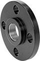
 |  |
Assembled | Exploded |
Bolt Hole | Port | For Carbon Steel Fittings | For 316/316L Stainless Steel Fittings | ||||||||||||||||
|---|---|---|---|---|---|---|---|---|---|---|---|---|---|---|---|---|---|---|---|
Pipe Size | Flange OD | For Bolt Dia. | Dia. | No. of | Bolt Circle Dia. | Pipe Size | No. of | Includes | Specs. Met | For Use With | Temp. | Pressure Class | For Pipe Material | Each | For Pipe Material | Each | |||
| 4 | 10" | 3/4" | 13/16" | 8 | 7 7/8" | 1/2 | 2 | Gaskets, Jack Bolts, Nuts, Port Plugs, Threaded Rods | ASME B16.36 | Air, Natural Gas, Oil, Water | Not Rated | 300 | Carbon Steel | 5291N23 | 0000000 | 316/316L Stainless Steel | 5291N36 | 000000000 | |
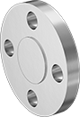
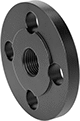
High-Pressure Galvanized Iron and Steel Threaded Pipe Flanges
 |  |
Front | Raised Surface on Back |
Pipe Size | Bolt Hole | ||||||||||||||
|---|---|---|---|---|---|---|---|---|---|---|---|---|---|---|---|
(A) | (B) | Flanged Connection Surface (B) | Flange OD | For Bolt Dia. | Dia. | No. Of | Bolt Circle Dia. | Pressure Class | Material | Max. Pressure @ Temp. | Max. Steam Pressure @ Temp. | Each | |||
NPT Female | |||||||||||||||
| 4 | 4 | Raised | 10" | 7/8" | 0.88" | 8 | 7 7/8" | 300 | Galvanized Steel | 600 psi @ 72° F | Not Rated | 1733N18 | 0000000 | ||
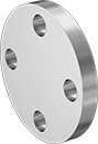
FM-Approved Low-Pressure Iron and Steel Threaded Pipe Flanges
 |
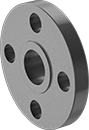
Front |
Pipe Size | Bolt Hole | ||||||||||||||
|---|---|---|---|---|---|---|---|---|---|---|---|---|---|---|---|
(A) | (B) | Flanged Connection Surface (B) | Flange OD | For Bolt Dia. | Dia. | No. Of | Bolt Circle Dia. | Material | Max. Pressure @ Temp. | Max. Steam Pressure @ Temp. | Certification | Each | |||
NPT Female | |||||||||||||||
| 5 | 5 | Flat | 10" | 3/4" | 7/8" | 8 | 8 1/2" | Cast Iron | 125 psi @ 72° F | 125 psi @ 350° F | FM Approved, UL Listed | 68185K131 | 0000000 | ||
Low-Pressure Galvanized Iron and Steel Threaded Pipe Flanges
 |  |
Front | Raised Surface on Back |
Pipe Size | Bolt Hole | ||||||||||||||
|---|---|---|---|---|---|---|---|---|---|---|---|---|---|---|---|
(A) | (B) | Flanged Connection Surface (B) | Flange OD | For Bolt Dia. | Dia. | No. Of | Bolt Circle Dia. | Pressure Class | Material | Max. Pressure @ Temp. | Max. Steam Pressure @ Temp. | Each | |||
NPT Female | |||||||||||||||
| 5 | 5 | Raised | 10" | 3/4" | 7/8" | 8 | 8 1/2" | 150 | Galvanized Steel | 285 psi @ 72° F | 150 psi @ 300° F | 7551K129 | 0000000 | ||
High-Temperature All-Metal Pipe Expansion Joints with Flanged Ends
 |
Pipe Expansion Joints | Expansion Joint Liners | |||||||||||||||||
|---|---|---|---|---|---|---|---|---|---|---|---|---|---|---|---|---|---|---|
Distance | Unthreaded Bolt Holes | |||||||||||||||||
Flange OD | Pipe Size | Lg. | No. of Bolt Holes | Compression | Expansion | Offset | Max. Pressure @ Temp. | Expansion Joint Type | Flange Material | For Use With | Temp. Range, ° F | Max. Vacuum @ Temp. | Bolt Hole Size | Each | Each | |||
| 10" | 5 | 6" | 8 | 15/16" | 5/16" | 3/16" | 150 psi @ 72° F | Bellow | Steel | Air, Natural Gas, Oil, Steam, Water | -20 to 800 | 29 in. Hg @ 72° F | 7/8" | 9413K65 | 0000000 | 9413K45 | 0000000 | |
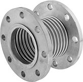
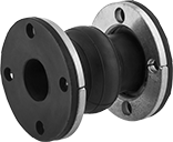
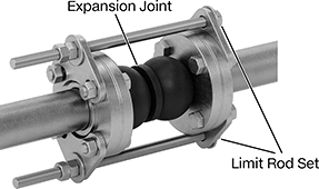
Pipe Expansion Joints with Flanged Ends
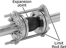 |
Shown Installed on a Flanged Pipe |
 | 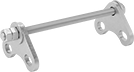 |
Expansion Joint | Limit Rod |
Pipe Expansion Joints | Limit Rod Sets | |||||||||||||||||||||
|---|---|---|---|---|---|---|---|---|---|---|---|---|---|---|---|---|---|---|---|---|---|---|
Distance | Threaded Bolt Holes | Unthreaded Bolt Holes | ||||||||||||||||||||
Flange OD | Pipe Size | Lg. | No. of Bolt Holes | Compression | Expansion | Offset | Max. Pressure @ Temp. | Expansion Joint Type | Flange Material | Reinforcement Material | For Use With | Temp. Range, ° F | Max. Vacuum @ Temp. | Bolt Hole Thread Size | Each | For Bolt Dia. | Each | Pair | ||||
| 10" | 5 | 6" | 8 | 3/4" | 1/2" | 1/2" | 220 psi @ 72° F | Single Bulb | Zinc-Plated Steel | Nylon | Nonabrasive Slurries, Water | -10 to 220 | 26 in. Hg @ 72° F | 3/4"-10 | 9175K37 | 0000000 | 7/8" | 9175K18 | 0000000 | 9175K87 | 0000000 | |
| |
Expansion Joint | Limit Rod |
Pipe Expansion Joints | Limit Rod Sets | ||||||||||||||||||
|---|---|---|---|---|---|---|---|---|---|---|---|---|---|---|---|---|---|---|---|
Distance | Unthreaded Bolt Holes | ||||||||||||||||||
Flange OD | Pipe Size | Lg. | No. of Bolt Holes | Compression | Expansion | Offset | Max. Pressure @ Temp. | Expansion Joint Type | Flange Material | Reinforcement Material | For Use With | Temp. Range, ° F | Max. Vacuum @ Temp. | For Bolt Dia. | Each | Pair | |||
| 10" | 5 | 6" | 8 | 3/4" | 1/2" | 1/2" | 220 psi @ 72° F | Single Bulb | Zinc-Plated Steel | Nylon | Alcohol, Water | -20 to 250 | 26 in. Hg @ 72° F | 7/8" | 9175K57 | 0000000 | 9175K87 | 0000000 | |
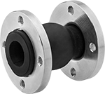
Pipe Expansion Joints with Sealing Flanged Ends for Metal Pipe
 |
Shown Installed on a Flanged Pipe |
 | |
Expansion Joint | Limit Rod |
Pipe Expansion Joints | Limit Rod Sets | ||||||||||||||||||
|---|---|---|---|---|---|---|---|---|---|---|---|---|---|---|---|---|---|---|---|
Distance | Unthreaded Bolt Holes | ||||||||||||||||||
Flange OD | Pipe Size | Lg. | No. of Bolt Holes | Compression | Expansion | Offset | Max. Pressure @ Temp. | Expansion Joint Type | Flange Material | Reinforcement Material | For Use With | Temp. Range, ° F | Max. Vacuum @ Temp. | Bolt Hole Size | Each | Pair | |||
| 10" | 5 | 6" | 8 | 1 1/4" | 5/8" | 9/16" | 210 psi @ 72° F | Single Bulb | Neoprene | Metal, Yarn | Coolant, Grease, Hydraulic Fluid, Water | -65 to 220 | 29 in. Hg @ 72° F | 7/8" | 4528K56 | 0000000 | 9175K87 | 0000000 | |
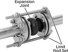
Pipe Expansion Joints with Flanged Ends for High Vibration
 |
Shown Installed on a Flanged Pipe |
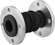 | 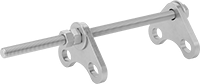 |
Expansion Joint | Limit Rod |
Pipe Expansion Joints | Limit Rod Sets | |||||||||||||||||||||
|---|---|---|---|---|---|---|---|---|---|---|---|---|---|---|---|---|---|---|---|---|---|---|
Distance | Threaded Bolt Holes | Unthreaded Bolt Holes | ||||||||||||||||||||
Flange OD | Pipe Size | Lg. | No. of Bolt Holes | Compression | Expansion | Offset | Max. Pressure @ Temp. | Expansion Joint Type | Flange Material | Reinforcement Material | For Use With | Temp. Range, ° F | Max. Vacuum @ Temp. | Bolt Hole Thread Size | Each | Bolt Hole Size | Each | Pair | ||||
| 10" | 5 | 9" | 8 | 2" | 1 3/8" | 1 9/16" | 220 psi @ 72° F | Double Bulb | Zinc-Plated Steel | Nylon | Grain Alcohol, Nonabrasive Slurries, Water | -10 to 220 | 26 in. Hg @ 72° F | 3/4"-10 | 6819K66 | 0000000 | 7/8" | 6819K52 | 0000000 | 6819K77 | 0000000 | |
| |
Expansion Joint | Limit Rod |
Pipe Expansion Joints | Limit Rod Sets | ||||||||||||||||||
|---|---|---|---|---|---|---|---|---|---|---|---|---|---|---|---|---|---|---|---|
Distance | Unthreaded Bolt Holes | ||||||||||||||||||
Flange OD | Pipe Size | Lg. | No. of Bolt Holes | Compression | Expansion | Offset | Max. Pressure @ Temp. | Expansion Joint Type | Flange Material | Reinforcement Material | For Use With | Temp. Range, ° F | Max. Vacuum @ Temp. | Bolt Hole Size | Each | Pair | |||
| 10" | 5 | 9" | 8 | 2" | 1 3/8" | 1 9/16" | 220 psi @ 72° F | Double Bulb | Zinc-Plated Steel | Nylon | Alcohol, Water | -20 to 250 | 26 in. Hg @ 72° F | 7/8" | 6819K86 | 0000000 | 6819K77 | 0000000 | |
