


Filter by
System of Measurement
Flanged Connection Surface


Maximum Pressure @ Temperature
Thread Type

Shape

Bolt Hole Diameter
Bolt Hole Center-to-Center
Number of Bolt Holes
RoHS
DFARS Specialty Metals

About Pipe and Fittings
Measure your pipe and fittings to identify their pipe size, thread size, schedule, and thread type. Then, find compatible components.


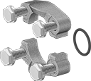
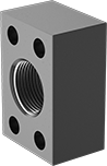
SAE High-Pressure Stainless Steel Threaded Two-Piece Pipe Flanges
Forged Flanges
 |
Flanged O-Ring Groove |
Forged flanges have better strength than cast flanges.
316/316L Stainless Steel—Flanges are the most corrosion resistant. They stand up to wet environments, just like 304 stainless steel flanges, but unlike 304 stainless steel, they will not corrode from salt water, chlorine solutions, and chemicals.
Bolt Hole | 316/316L Stainless Steel | |||||||||
|---|---|---|---|---|---|---|---|---|---|---|
SAE Pipe Flange Size | Dash Size | Flanged Connection Surface | For Bolt Dia. | Dia. | No. Of | Max. Pressure @ Temp. | Each | |||
Flanged | ||||||||||
| 3/4 | 12 | O-Ring Groove | 3/8" | 0.406" | 4 | 5,000 psi @ 72° F | 1723N37 | 0000000 | ||
| 3/4 | 12 | O-Ring Groove | 10 mm | 10 mm | 4 | 5,000 psi @ 72° F | 1723N42 | 000000 | ||
| 1 | 16 | O-Ring Groove | 3/8" | 0.406" | 4 | 4,600 psi @ 72° F | 1723N38 | 000000 | ||
| 1 | 16 | O-Ring Groove | 10 mm | 10 mm | 4 | 4,600 psi @ 72° F | 1723N43 | 000000 | ||
| 1 1/2 | 24 | O-Ring Groove | 1/2" | 0.531" | 4 | 3,000 psi @ 72° F | 1723N39 | 000000 | ||
| 1 1/2 | 24 | O-Ring Groove | 12 mm | 13 mm | 4 | 3,000 psi @ 72° F | 1723N44 | 000000 | ||
| 2 | 32 | O-Ring Groove | 1/2" | 0.531" | 4 | 3,000 psi @ 72° F | 1723N41 | 000000 | ||
| 2 | 32 | O-Ring Groove | 12 mm | 13 mm | 4 | 3,000 psi @ 72° F | 1723N45 | 000000 | ||
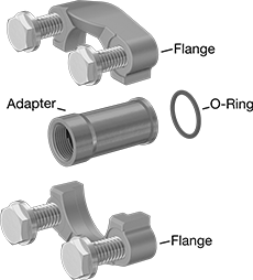
Machined Flange Adapters
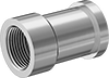 |
Female |
NPTF Thread—NPTF (Dryseal) threads are compatible with NPT threads.
316/316L Stainless Steel—Flanges are the most corrosion resistant. They stand up to wet environments, just like 304 stainless steel flanges, but unlike 304 stainless steel, they will not corrode from salt water, chlorine solutions, and chemicals.
316/316L Stainless Steel | ||||||||
|---|---|---|---|---|---|---|---|---|
Pipe Size (A) | For SAE Pipe Flange Size (B) | Dash Size (A) | For Flanged Connection Surface | Max. Pressure @ Temp. | Each | |||
NPTF Female | ||||||||
| 3/4 | 3/4 | 12 | O-Ring Groove | 5,000 psi @ 72° F | 1723N51 | 0000000 | ||
| 1 | 1 | 16 | O-Ring Groove | 4,600 psi @ 72° F | 1723N52 | 000000 | ||
| 1 1/2 | 1 1/2 | 24 | O-Ring Groove | 3,000 psi @ 72° F | 1723N53 | 000000 | ||
| 2 | 2 | 32 | O-Ring Groove | 3,000 psi @ 72° F | 1723N54 | 000000 | ||
SAE High-Pressure Stainless Steel Threaded Pipe Flanges
Machined Flanges
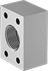 |  |  |  |
Flat Front | Flat Back | O-Ring Groove Front | O-Ring Groove Back |
NPTF Thread—NPTF (Dryseal) threads are compatible with NPT threads.
316/316L Stainless Steel—Flanges are the most corrosion resistant. They stand up to wet environments, just like 304 stainless steel flanges, but unlike 304 stainless steel, they will not corrode from salt water, chlorine solutions, and chemicals.
Dash Size | Bolt Hole | 316/316L Stainless Steel | ||||||||||
|---|---|---|---|---|---|---|---|---|---|---|---|---|
Pipe Size (A) | SAE Pipe Flange Size (B) | (A) | (B) | Flanged Connection Surface (B) | For Bolt Dia. | Dia. | No. Of | Max. Pressure @ Temp. | Each | |||
NPTF Female | ||||||||||||
| 3/4 | 3/4 | 12 | 12 | O-Ring Groove | 3/8" | 0.406" | 4 | 2,500 psi @ 72° F | 1723N15 | 0000000 | ||
| 1 | 1 | 16 | 16 | Flat | 3/8" | 0.312" | 4 | 2,000 psi @ 72° F | 1723N12 | 000000 | ||
| 1 | 1 | 16 | 16 | O-Ring Groove | 3/8" | 0.406" | 4 | 2,000 psi @ 72° F | 1723N16 | 000000 | ||
| 1 1/2 | 1 1/2 | 24 | 24 | Flat | 1/2" | 0.422" | 4 | 1,000 psi @ 72° F | 1723N13 | 000000 | ||
| 1 1/2 | 1 1/2 | 24 | 24 | O-Ring Groove | 1/2" | 0.531" | 4 | 1,000 psi @ 72° F | 1723N17 | 000000 | ||
| 2 | 2 | 32 | 32 | Flat | 1/2" | 0.422" | 4 | 1,000 psi @ 72° F | 1723N14 | 000000 | ||
| 2 | 2 | 32 | 32 | O-Ring Groove | 1/2" | 0.531" | 4 | 1,000 psi @ 72° F | 1723N18 | 000000 | ||
SAE High-Pressure Iron and Steel Threaded Pipe Flanges
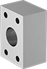
Machined Flanges
 |  |  |
Front | Back (Flat) | Back (O-Ring Groove) |
Dash Size | Bolt Hole | ||||||||||||
|---|---|---|---|---|---|---|---|---|---|---|---|---|---|
Pipe Size (A) | SAE Pipe Flange Size (B) | (A) | (B) | Flanged Connection Surface (B) | For Bolt Dia. | Dia. | No. Of | Material | Max. Pressure @ Temp. | Each | |||
NPTF Female | |||||||||||||
| 3/4 | 3/4 | 12 | 12 | Flat | 3/8" | 3/8" | 4 | Steel | 3,000 psi @ 72° F | 2125N1 | 000000 | ||
| 3/4 | 3/4 | 12 | 12 | O-Ring Groove | 3/8" | 0.41" | 4 | Steel | 3,000 psi @ 72° F | 2125N14 | 00000 | ||
| 1 | 1 | 16 | 16 | Flat | 3/8" | 3/8" | 4 | Steel | 3,000 psi @ 72° F | 2125N11 | 00000 | ||
| 1 | 1 | 16 | 16 | O-Ring Groove | 3/8" | 0.41" | 4 | Steel | 3,000 psi @ 72° F | 2125N15 | 00000 | ||
| 1 | 1 | 16 | 16 | O-Ring Groove | 10 mm | 10.5 mm | 4 | Steel | 3,000 psi @ 72° F | 2125N19 | 00000 | ||
| 1 1/2 | 1 1/2 | 24 | 24 | Flat | 1/2" | 1/2" | 4 | Steel | 3,000 psi @ 72° F | 2125N12 | 00000 | ||
| 1 1/2 | 1 1/2 | 24 | 24 | O-Ring Groove | 1/2" | 0.53" | 4 | Steel | 3,000 psi @ 72° F | 2125N16 | 00000 | ||
| 2 | 2 | 32 | 32 | Flat | 1/2" | 1/2" | 4 | Steel | 3,000 psi @ 72° F | 2125N13 | 00000 | ||
| 2 | 2 | 32 | 32 | O-Ring Groove | 1/2" | 0.53" | 4 | Steel | 3,000 psi @ 72° F | 2125N17 | 00000 | ||
| 2 | 2 | 32 | 32 | O-Ring Groove | 12 mm | 13.3 mm | 4 | Steel | 3,000 psi @ 72° F | 2125N21 | 00000 | ||
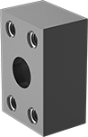
SAE High-Pressure Iron and Steel Threaded Two-Piece Pipe Flanges
Forged Flanges
 |
Flange |
Bolt Hole | |||||||||||
|---|---|---|---|---|---|---|---|---|---|---|---|
SAE Pipe Flange Size | Dash Size | Flanged Connection Surface | For Bolt Dia. | Dia. | No. Of | Material | Max. Pressure @ Temp. | Each | |||
Flanged | |||||||||||
| 1 | 16 | O-Ring Groove | 3/8" | 0.41" | 4 | Steel | 3,000 psi @ 72° F | 2125N59 | 000000 | ||
| 1 | 16 | O-Ring Groove | 10 mm | 11 mm | 4 | Steel | 3,000 psi @ 72° F | 2125N63 | 00000 | ||
| 1 1/2 | 24 | O-Ring Groove | 1/2" | 0.53" | 4 | Steel | 3,000 psi @ 72° F | 2125N6 | 00000 | ||
| 1 1/2 | 24 | O-Ring Groove | 12 mm | 13 mm | 4 | Steel | 3,000 psi @ 72° F | 2125N64 | 00000 | ||
| 2 | 32 | O-Ring Groove | 1/2" | 0.53" | 4 | Steel | 3,000 psi @ 72° F | 2125N61 | 00000 | ||
| 2 | 32 | O-Ring Groove | 12 mm | 13 mm | 4 | Steel | 3,000 psi @ 72° F | 2125N65 | 00000 | ||
Machined Flange Adapters
SAE Extreme-Pressure Iron and Steel Threaded Two-Piece Pipe Flanges
Forged Flanges
|
Flange |
Bolt Hole | |||||||||||
|---|---|---|---|---|---|---|---|---|---|---|---|
SAE Pipe Flange Size | Dash Size | Flanged Connection Surface | For Bolt Dia. | Dia. | No. Of | Material | Max. Pressure @ Temp. | Each | |||
Flanged | |||||||||||
| 3/4 | 12 | O-Ring Groove | 3/8" | 0.41" | 4 | Steel | 6,000 psi @ 72° F | 2125N66 | 000000 | ||
| 3/4 | 12 | O-Ring Groove | 10 mm | 11 mm | 4 | Steel | 6,000 psi @ 72° F | 2125N71 | 00000 | ||
| 1 | 16 | O-Ring Groove | 0.438" | 0.47" | 4 | Steel | 6,000 psi @ 72° F | 2125N67 | 00000 | ||
| 1 | 16 | O-Ring Groove | 12 mm | 13 mm | 4 | Steel | 6,000 psi @ 72° F | 2125N72 | 00000 | ||
| 1 1/2 | 24 | O-Ring Groove | 5/8" | 0.66" | 4 | Steel | 6,000 psi @ 72° F | 2125N68 | 00000 | ||
| 1 1/2 | 24 | O-Ring Groove | 16 mm | 17 mm | 4 | Steel | 6,000 psi @ 72° F | 2125N7 | 00000 | ||
| 2 | 32 | O-Ring Groove | 3/4" | 0.78" | 4 | Steel | 6,000 psi @ 72° F | 2125N69 | 000000 | ||
| 2 | 32 | O-Ring Groove | 20 mm | 21 mm | 4 | Steel | 6,000 psi @ 72° F | 2125N73 | 000000 | ||
Machined Flange Adapters
|
Flange |
Pipe Size (A) | For SAE Pipe Flange Size (B) | Dash Size (A) | For Flanged Connection Surface | Material | Max. Pressure @ Temp. | Each | |||
|---|---|---|---|---|---|---|---|---|---|
NPTF Female | |||||||||
| 3/4 | 3/4 | 12 | O-Ring Groove | Steel | 6,000 psi @ 72° F | 2125N86 | 000000 | ||
| 1 | 1 | 16 | O-Ring Groove | Steel | 6,000 psi @ 72° F | 2125N87 | 00000 | ||
| 1 1/2 | 1 1/2 | 24 | O-Ring Groove | Steel | 6,000 psi @ 72° F | 2125N88 | 000000 | ||
| 2 | 2 | 32 | O-Ring Groove | Steel | 6,000 psi @ 72° F | 2125N89 | 000000 | ||
Low-Pressure Iron and Steel Threaded Pipe Fittings
Straight Adapters for Tanks
 |
Female × Butt Weld (For Curved Surface) |
Pipe Size | For Hole Diameter (B) | OD | For Tank OD (B) | For Tank Surface (B) | Material | Max. Pressure @ Temp. | Each | |||
|---|---|---|---|---|---|---|---|---|---|---|
NPTF Female × Butt Weld | ||||||||||
| 3/4 | 1 1/8" | 2 3/16" | 20" | Curved | Steel | Not Rated | 1698T11 | 00000 | ||
180° Bend Connectors
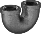 |
180° bend connectors are also known as U-bends.
Pipe Size | Material | Max. Pressure @ Temp. | Max. Steam Pressure @ Temp. | Certification | Shape | Each | |||
|---|---|---|---|---|---|---|---|---|---|
NPT Female | |||||||||
| 3/4 | Iron | 150 psi @ 72° F | 150 psi @ 350° F | UL Listed | 180° Bend | 44605K564 | 000000 | ||
