


About Float Switches
More
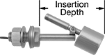
Vertical-Mount Float Switches for Chemicals
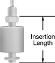
Mount these switches from outside the tank through a threaded connection at the top or bottom of your tank. They activate process equipment such as pumps or motors when the chemical level in your tank reaches the float. Choose the switch with a stainless steel float for durability in harsh conditions.
Switches with splash guard minimize false switch activation caused by splashing liquid.
| Pipe Size | Thread Type | Gender | Min. Specific Gravity | Max. Pressure | Temp. Range, °F | Insertion Dp. | Switch Starting Position | Industry Designation | Current | Float Ht. | Overall Dia. | Electrical Connection | Each | |
120V AC/240V AC Input Voltage | ||||||||||||||
|---|---|---|---|---|---|---|---|---|---|---|---|---|---|---|
Polypropylene Plastic Float | ||||||||||||||
| 1/4 | NPT | Male | 0.85 | 100 psi @ 70° F | 35° to 220° | 2 7/8" | 1 Off (Normally Open)/1 On (Normally Closed) | SPST-NO SPST-NC | 0.5 A @ 120 V AC | 2" | 1 1/2" | Wire Leads | 00000000 | 000000 |
| 1/4 | NPT | Male | 0.85 | 100 psi @ 70° F | 35° to 220° | 2 7/8" | 1 Off (Normally Open)/1 On (Normally Closed) | SPST-NO SPST-NC | 1 A @ 120 V AC | 2" | 1 1/2" | Wire Leads | 00000000 | 00000 |
Polypropylene Plastic Float with Splash Guard | ||||||||||||||
| 1/8 | NPT | Male | 0.9 | 100 psi @ 70° F | 35° to 220° | 1 7/8" | 1 Off (Normally Open)/1 On (Normally Closed) | SPST-NO SPST-NC | 0.3 A @ 120 V AC | 1" | 1 1/2" | Wire Leads | 00000000 | 00000 |
| 1/4 | NPT | Male | 0.85 | 100 psi @ 70° F | 35° to 220° | 2 7/8" | 1 Off (Normally Open)/1 On (Normally Closed) | SPST-NO SPST-NC | 0.5 A @ 120 V AC | 2" | 2" | Wire Leads | 00000000 | 00000 |
PVDF Plastic Float with Splash Guard | ||||||||||||||
| 1/8 | NPT | Male | 0.95 | 15 psi @ 70° F | 35° to 220° | 1 7/8" | 1 Off (Normally Open)/1 On (Normally Closed) | SPST-NO SPST-NC | 0.3 A @ 120 V AC | 1" | 1 1/2" | Wire Leads | 00000000 | 00000 |
316 Stainless Steel Float with Splash Guard | ||||||||||||||
| 1/4 | NPT | Male | 0.65 | 200 psi @ 70° F | 35° to 480° | 2 15/16" | 1 Off (Normally Open)/1 On (Normally Closed) | SPST-NO SPST-NC | 0.5 A @ 120 V AC | 2 1/8" | 2 3/8" | Wire Leads | 0000000 | 000000 |
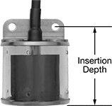
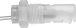
Through-Wall Vertical-Mount Float Switches for Chemicals
Install these switches into an unthreaded hole at the top or bottom of your tank and secure with a nut from inside the tank. They activate process equipment such as pumps or motors when the chemical level in your tank reaches the float.
| For Hole Dia. | Min. Specific Gravity | Max. Pressure | Temp. Range, °F | Insertion Dp. | Switch Starting Position | Industry Designation | Current | Float Ht. | Overall Dia. | Electrical Connection | Includes | Each | |
120V AC Input Voltage | |||||||||||||
|---|---|---|---|---|---|---|---|---|---|---|---|---|---|
Polypropylene Plastic Float | |||||||||||||
| 3/8" | 0.7 | 50 psi @ 70° F | 35° to 220° | 1 1/4" | 1 Off (Normally Open) | SPST-NO | 0.12 A @ 120 V AC | 5/8" | 9/16" | Wire Leads | Mounting Nut | 00000000 | 000000 |
| 3/8" | 0.7 | 50 psi @ 70° F | 35° to 220° | 1 1/4" | 1 On (Normally Closed) | SPST-NC | 0.12 A @ 120 V AC | 5/8" | 9/16" | Wire Leads | Mounting Nut | 00000000 | 00000 |
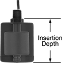
Vertical-Mount Float Switches with Brackets for Chemicals
Use the included bracket to mount these switches to the inside of your tank. They activate process equipment such as pumps or motors when the chemical level in your tank reaches the float. A splash guard minimizes false switch activation caused by splashing liquid. Choose the switch with a stainless steel float for durability in harsh conditions.
| Min. Specific Gravity | Max. Pressure | Temp. Range, °F | Insertion Dp. | Switch Starting Position | Industry Designation | Current | Float Ht. | Overall Dia. | Each | |
120V AC/240V AC Input Voltage | ||||||||||
|---|---|---|---|---|---|---|---|---|---|---|
Polypropylene Plastic Float with Splash Guard | ||||||||||
| 0.85 | 100 psi @ 70° F | 35° to 220° | 3 7/8" | 1 Off (Normally Open)/1 On (Normally Closed) | SPST-NO SPST-NC | 0.5 A @ 120 V AC | 2" | 2 1/2" | 0000000 | 0000000 |
316 Stainless Steel Float with Splash Guard | ||||||||||
| 0.65 | 85 psi @ 70° F | 35° to 230° | 3 7/8" | 1 Off (Normally Open)/1 On (Normally Closed) | SPST-NO SPST-NC | 0.5 A @ 120 V AC | 2" | 2 1/2" | 0000000 | 000000 |
Through-Wall Horizontal-Mount Float Switches for Chemicals
Mount these switches through an unthreaded hole in your tank wall and secure with a nut from outside the tank. They activate process equipment such as pumps or motors when the chemical level in your tank reaches the float.
Switch with splash guard minimizes false switch activation caused by splashing liquid.
Float Switches | Replacement Floats | |||||||||||||
|---|---|---|---|---|---|---|---|---|---|---|---|---|---|---|
| For Hole Dia. | Min. Specific Gravity | Max. Pressure | Temp. Range, °F | Insertion Dp. | Switch Starting Position | Industry Designation | Current | Float Material | Electrical Connection | Includes | Each | Each | ||
120V AC/240V AC Input Voltage | ||||||||||||||
316 Stainless Steel Body with Splash Guard | ||||||||||||||
| 3/8" | 0.8 | 300 psi @ 70° F | -40° to 390° | 2 9/16" | 1 Off (Normally Open)/1 On (Normally Closed) | SPST-NO SPST-NC | 0.28 A @ 120 V AC | 316 Stainless Steel | Wire Leads | Mounting Nut | 00000000 | 0000000 | 0000000 | 000000 |
316 Stainless Steel Body | ||||||||||||||
| 1/2" | 0.8 | 100 psi @ 70° F | -40° to 390° | 3 3/16" | 1 Off (Normally Open)/1 On (Normally Closed) | SPST-NO SPST-NC | 0.28 A @ 120 V AC | 316 Stainless Steel | Wire Leads | Mounting Nut | 00000000 | 000000 | 000000 | 00 |
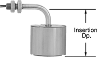
Horizontal-Mount Float Switches for Chemicals
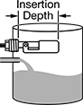
Install these switches into a threaded connection in your tank wall from outside the tank. They activate process equipment such as pumps or motors when the chemical level in your tank reaches the float.
Switches with splash guard minimize false switch activation caused by splashing liquid.
Pipe | Conduit | ||||||||||||||
|---|---|---|---|---|---|---|---|---|---|---|---|---|---|---|---|
| Size | Thread Type | Gender | Min. Specific Gravity | Max. Pressure | Temp. Range, °F | Insertion Dp. | Switch Starting Position | Industry Designation | Current | Float Material | Trade Size | Thread Type | Gender | Each | |
120V AC/240V AC Input Voltage | |||||||||||||||
PVDF Plastic Body | |||||||||||||||
| 1/2 | NPT | Male | 0.85 | 100 psi @ 70° F | -40° to 220° | 2 3/4" | 1 Off (Normally Open)/1 On (Normally Closed) | SPST-NO SPST-NC | 0.28 A @ 120 V AC | PVDF Plastic | 1/2 | NPT | Male | 0000000 | 000000 |
PVDF Plastic Body with Splash Guard | |||||||||||||||
| 1 | NPT | Male | 0.85 | 100 psi @ 70° F | -40° to 220° | 1 7/8" | 1 Off (Normally Open)/1 On (Normally Closed) | SPST-NO SPST-NC | 0.28 A @ 120 V AC | PVDF Plastic | 1/2 | NPT | Male | 0000000 | 000000 |
Polypropylene Plastic Body | |||||||||||||||
| 1/2 | NPT | Male | 0.7 | 100 psi @ 70° F | -40° to 220° | 2 3/4" | 1 Off (Normally Open)/1 On (Normally Closed) | SPST-NO SPST-NC | 0.28 A @ 120 V AC | Polypropylene Plastic | 1/4 | NPT | Male | 00000000 | 00000 |
Polypropylene Plastic Body with Splash Guard | |||||||||||||||
| 1 | NPT | Male | 0.7 | 100 psi @ 70° F | -40° to 220° | 1 7/8" | 1 Off (Normally Open)/1 On (Normally Closed) | SPST-NO SPST-NC | 0.28 A @ 120 V AC | Polypropylene Plastic | __ | __ | __ | 00000000 | 00000 |
| 1 | NPT | Male | 0.7 | 100 psi @ 70° F | -40° to 220° | 1 7/8" | 1 Off (Normally Open)/1 On (Normally Closed) | SPST-NO SPST-NC | 0.28 A @ 120 V AC | Polypropylene Plastic | 1/2 | NPT | Male | 00000000 | 00000 |
Hazardous Location Float Switches for Chemicals
Designed for use in areas where flammable substances are present, these switches are CSA certified for hazardous locations. Mount them through a tank wall.
Style A meets Class I, Divisions 1 and 2, Groups A, B, C, and D; Class II, Divisions 1 and 2, Groups E, F, and G; and Class III, Divisions 1 and 2.
Pipe | Conduit | ||||||||||||||||
|---|---|---|---|---|---|---|---|---|---|---|---|---|---|---|---|---|---|
| Style | Size | Thread Type | Gender | Min. Specific Gravity | Max. Pressure | Temp. Range, °F | Insertion Dp. | Switch Starting Position | Industry Designation | Current | Float Material | Electrical Connection | Trade Size | Thread Type | Gender | Each | |
120V AC/240V AC Input Voltage | |||||||||||||||||
316 Stainless Steel Body | |||||||||||||||||
| A | 1/2 | NPT | Male | 0.7 | 300 psi @ 70° F | 0° to 390° | 4 5/8" | 1 Off (Normally Open)/1 On (Normally Closed) | SPST-NO SPST-NC | 0.28 A @ 120 V AC | 316 Stainless Steel | Wire Leads | 1/4 | NPT | Male | 00000000 | 0000000 |
| A | 1/2 | NPT | Male | 0.7 | 300 psi @ 70° F | 0° to 390° | 4 5/8" | 1 Off (Normally Open)/1 On (Normally Closed) | SPST-NO SPST-NC | 0.28 A @ 120 V AC | 316 Stainless Steel | Wire Leads | 1/2 | NPT | Male | 00000000 | 000000 |
| A | 1 | NPT | Male | 0.7 | 300 psi @ 70° F | 0° to 390° | 4 5/8" | 1 Off (Normally Open)/1 On (Normally Closed) | SPST-NO SPST-NC | 0.28 A @ 120 V AC | 316 Stainless Steel | Wire Leads | 1/2 | NPT | Male | 00000000 | 000000 |