


Connection Style Connection Style | Show |
|---|
|
Connection Style Connection Style | Hide |
|---|
Body Material Body Material |
|---|
|
Shape Shape |
|---|
| Straight | |
Connection Type Connection Type |
|---|
| Pipe | |
For Use With For Use With |
|---|
|
Valve Type Valve Type |
|---|
|
Port Type Port Type |
|---|
 | Full |
Ball Material Ball Material |
|---|
|
Maximum Pressure Maximum Pressure |
|---|
|
Mounting Orientation Mounting Orientation |
|---|
|
Maximum Temperature Maximum Temperature |
|---|
|
Minimum Temperature Minimum Temperature |
|---|
|
RoHS (Restriction of Hazardous Substances) RoHS (Restriction ofHazardous Substances) |
|---|
|
DFARS (Defense Acquisition Regulations Supplement) DFARS (Defense AcquisitionRegulations Supplement) |
|---|
Electrical Connection Type Electrical Connection Type |
|---|
|
Industry Designation Industry Designation |
|---|
REACH (Registration, Evaluation, Authorization and Restriction of Chemicals) REACH (Registration,Evaluation, Authorization and Restriction of Chemicals) |
|---|
|
About Actuated On/Off Valves
More
Motor-Driven On/Off Valves with Socket-Connect Fittings for Drinking Water
- Valve Type: Ball
- For Use With: Drinking Water
- Seal Material: EPDM Rubber
- Specifications Met: NSF/ANSI 61
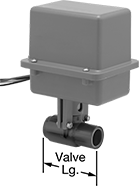
Insert unthreaded pipe into the socket ends and bond with PVC primer and cement to create a permanent, leak-tight connection. These valves meet NSF/ANSI Standard 61 for drinking water applications. All operate on electricity to automatically start and stop flow. Valves don’t require a minimum pressure drop between the inlet and outlet for operation. They are normally closed unless actuated. All valves are full port, so they do not restrict flow.
The actuator is directly mounted to the valve body to minimize movement and reduce wear. Valves meet NEMA 4X for resistance to washdowns, splashing water, corrosive liquid, and dust.
Flow coefficient (Cv) is the amount of water (in gallons per minute) at 60° F that will flow through a fully open valve with a difference of 1 psi between the inlet and the outlet.
![]() For technical drawings and 3-D models, click on a part number.
For technical drawings and 3-D models, click on a part number.
Overall | ||||||||||||
|---|---|---|---|---|---|---|---|---|---|---|---|---|
| Pipe Size | Gender | Flow Coefficient (Cv) | Max. Pressure | Pressure Drop | Actuation Time, sec. | Temp. Range, °F | Valve Lg. | Lg. | Ht. | Environmental Rating | Each | |
Dark Gray PVC Plastic Body with Wire Leads | ||||||||||||
Normally Closed—120V AC | ||||||||||||
| 1/2 | Female | 42 | 235 psi @ 100° F | Zero Pressure Drop | 5 | 40° to 140° | 3 1/16" | 5 3/8" | 7 3/8" | NEMA 4X | 0000000 | 0000000 |
| 3/4 | Female | 87 | 235 psi @ 100° F | Zero Pressure Drop | 5 | 40° to 140° | 3 9/16" | 5 3/8" | 7 13/16" | NEMA 4X | 0000000 | 000000 |
| 1 | Female | 157 | 235 psi @ 100° F | Zero Pressure Drop | 5 | 40° to 140° | 4" | 5 3/8" | 8 1/8" | NEMA 4X | 0000000 | 000000 |
| 1 1/4 | Female | 311 | 235 psi @ 100° F | Zero Pressure Drop | 5 | 40° to 140° | 4 5/8" | 6 1/16" | 8 15/16" | NEMA 4X | 0000000 | 000000 |
| 1 1/2 | Female | 429 | 235 psi @ 100° F | Zero Pressure Drop | 5 | 40° to 140° | 5 1/4" | 6 1/16" | 9 3/8" | NEMA 4X | 0000000 | 000000 |
| 2 | Female | 768 | 235 psi @ 100° F | Zero Pressure Drop | 5 | 40° to 140° | 6" | 6 1/16" | 10 3/16" | NEMA 4X | 0000000 | 000000 |
Compact Insertion Flow Switches for Water
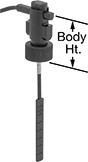
At half the height of standard insertion flow switches, these are often installed in tees or pipe outlets in low-clearance areas. They’re installed in tees or pipe outlets to detect the flow rate of liquid in contact with the sensing paddle. They activate or deactivate equipment when the flow rate reaches your set point. Switches are single pole, double throw (SPDT) and can be installed to turn one circuit from “off” to “on” (normally open). The flow rate varies based on the pipe size and the paddle length.
Maximum flow rate is how much water can temporarily flow through your pipe without damaging the switch.
Switches with a socket-weld connection are for use with unthreaded male pipe.
Switches with a trimmable paddle can be cut to fit a range of pipe sizes. Those with a 301 stainless steel paddle can be used with higher maximum flow rates than switches with a Noryl plastic paddle.
![]() For technical drawings and 3-D models, click on a part number.
For technical drawings and 3-D models, click on a part number.
| Pipe Size | For Pipe Size | Set Point, gpm | Set Point Adjustment Method | Paddle Material | Max. Flow Rate, gpm | Max. Pressure | Temp. Range, °F | Voltage | Current | Body Ht. | Environmental Rating | Each | |
Noryl Plastic Body | |||||||||||||
|---|---|---|---|---|---|---|---|---|---|---|---|---|---|
Socket-Weld Connection | |||||||||||||
| 1/2 | 1/2 | 0.97 to 1.03 | __ | Noryl Plastic | 7.9 | 160 psi @ 70 ° F | -13° to 212° | 120V AC/ 240V AC | 1 A @ 120 V AC | 2 1/2" | IP65 | 00000000 | 0000000 |
| 3/4 | 3/4 | 1.87 to 1.94 | __ | Noryl Plastic | 21 | 160 psi @ 70 ° F | -13° to 212° | 120V AC/ 240V AC | 1 A @ 120 V AC | 2 1/2" | IP65 | 00000000 | 000000 |
| 3/4 | 1 1/2 to 3 | 8 to 23 | Trimmable Paddles | 301 Stainless Steel | 650 | 160 psi @ 70 ° F | -13° to 212° | 120V AC/ 240V AC | 1 A @ 120 V AC | 2 1/2" | IP65 | 00000000 | 000000 |
| 3/4 | 1 1/2 to 3 | 8 to 23 | Trimmable Paddles | Noryl Plastic | 390 | 160 psi @ 70 ° F | -13° to 212° | 120V AC/ 240V AC | 1 A @ 120 V AC | 2 1/2" | IP65 | 0000000 | 000000 |
| 1 | 1 | 2.4 to 2.7 | __ | Noryl Plastic | 40 | 160 psi @ 70 ° F | -13° to 212° | 120V AC/ 240V AC | 1 A @ 120 V AC | 2 1/2" | IP65 | 00000000 | 000000 |