


For Use With For Use With | Show |
|---|
|
For Use With For Use With | Hide |
|---|
Thread Type Thread Type |
|---|
Body Material Body Material |
|---|
|
Shape Shape |
|---|
| Straight | |
Actuation Actuation |
|---|
|
Minimum Temperature Minimum Temperature |
|---|
|
Maximum Pressure Maximum Pressure |
|---|
|
Valve Function Valve Function |
|---|
|
Maximum Temperature Maximum Temperature |
|---|
|
Valve Type Valve Type |
|---|
|
Connection Type Connection Type |
|---|
| Pipe | |
Connection Style Connection Style |
|---|
 | Threaded |
Type Type |
|---|
|
Handle Style Handle Style |
|---|
| Wheel | |
RoHS (Restriction of Hazardous Substances) RoHS (Restriction ofHazardous Substances) |
|---|
|
DFARS (Defense Acquisition Regulations Supplement) DFARS (Defense AcquisitionRegulations Supplement) |
|---|
Valve Starting Position Valve Starting Position |
|---|
|
Overall Length Overall Length |
|---|

|
|
|
REACH (Registration, Evaluation, Authorization and Restriction of Chemicals) REACH (Registration,Evaluation, Authorization and Restriction of Chemicals) |
|---|
|
About Actuated On/Off Valves
More
About Flow-Adjustment Valves
More
Compact Threaded Flow-Adjustment Valves for Cryogenic Liquid
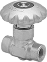
- Valve Type: Globe
- For Use With: Liquid Argon, Liquid Carbon Dioxide, Liquid Nitrogen
- Specifications Met: CGA G-4.1
Often used with portable cryogenic cylinders, these valves are a third of the height of other valves for cryogenic liquid. They are designed to withstand the extreme cold of liquid argon, liquid carbon dioxide, and liquid nitrogen; all are cleaned and bagged to meet CGA G-4.1 standards for oxygen service. These valves gradually open and close with multiple turns of the wheel handle to adjust and regulate flow. They have a nonrising stem that stays in the same position whether the valve is open or closed.
Flow coefficient (Cv) is the amount of water (in gallons per minute) at 60° F that will flow through a fully open valve with a difference of 1 psi between the inlet and the outlet.
![]() For technical drawings and 3-D models, click on a part number.
For technical drawings and 3-D models, click on a part number.
| Pipe Size | Flow Coefficient (Cv) | Max. Pressure | Temperature Range, °F | End-to-End Lg. | Stem Type | Each | |
Brass Body | |||||||
|---|---|---|---|---|---|---|---|
NPT Female × NPT Female | |||||||
| 1/4 | 1 | 600 psi @ 165° F | -320° to 165° | 2 1/2" | Nonrising | 00000000 | 0000000 |
| 3/8 | 1.8 | 600 psi @ 165° F | -320° to 165° | 2 1/2" | Nonrising | 00000000 | 000000 |
| 1/2 | 1.8 | 600 psi @ 165° F | -320° to 165° | 2 1/2" | Nonrising | 00000000 | 000000 |
Threaded Flow-Adjustment Valves for Cryogenic Liquid
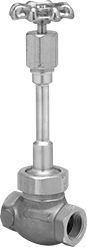
- Valve Type: Globe
- For Use With: Liquid Argon, Liquid Carbon Dioxide, Liquid Nitrogen
- Seal Material: Glass-Filled PTFE Plastic
- Specifications Met: CGA G-4.1
Designed to withstand the extreme cold of liquid argon, liquid carbon dioxide, and liquid nitrogen, these valves are cleaned and bagged to meet CGA G-4.1 standards for oxygen service. They gradually open and close with multiple turns of the wheel handle to adjust and regulate flow. All have a rising stem that lifts as the valve opens and lowers as the valve closes to provide a visual indication of whether flow is on or off.
Flow coefficient (Cv) is the amount of water (in gallons per minute) at 60° F that will flow through a fully open valve with a difference of 1 psi between the inlet and the outlet.
![]() For technical drawings and 3-D models, click on a part number.
For technical drawings and 3-D models, click on a part number.
| Pipe Size | Flow Coefficient (Cv) | Max. Pressure | Temperature Range, °F | End-to-End Lg. | Overall Ht. | Stem Type | Each | |
Bronze Body | ||||||||
|---|---|---|---|---|---|---|---|---|
NPT Female × NPT Female | ||||||||
| 1/2 | 3.3 | 600 psi @ 150° F | -325° to 150° | 2 5/8" | 8 5/16" | Rising | 00000000 | 0000000 |
| 3/4 | 6.3 | 400 psi @ 150° F | -325° to 150° | 3 3/16" | 10" | Rising | 00000000 | 000000 |
| 1 | 10 | 600 psi @ 150° F | -325° to 150° | 3 3/4" | 11 13/16" | Rising | 00000000 | 000000 |
| 1 1/2 | 26 | 400 psi @ 150° F | -325° to 150° | 4 3/4" | 16 1/2" | Rising | 00000000 | 000000 |
| 2 | 45 | 600 psi @ 150° F | -325° to 150° | 5 3/4" | 16 3/4" | Rising | 00000000 | 00000000 |
Stainless Steel Body | ||||||||
NPT Female × NPT Female | ||||||||
| 1/2 | 5 | 720 psi @ 150° F | -325° to 150° | 3 1/16" | 11 13/16" | Rising | 00000000 | 000000 |
| 1 | 14 | 720 psi @ 150° F | -325° to 150° | 3 15/16" | 12 1/16" | Rising | 00000000 | 000000 |
| 1 1/2 | 53 | 720 psi @ 150° F | -325° to 150° | 5" | 12 5/16" | Rising | 00000000 | 000000 |
| 2 | 53 | 720 psi @ 150° F | -325° to 150° | 5 15/16" | 12 5/8" | Rising | 00000000 | 000000 |
Solenoid On/Off Valves for Cryogenic Liquids
Built to withstand the extreme cold of liquid nitrogen and liquid oxygen, these valves are cleaned and bagged for high-purity applications. They operate on electricity to automatically start and stop flow.
All valves are normally closed unless actuated. The actuator is directly mounted to the valve body to minimize movement and reduce wear.
Zero pressure drop valves don’t require a minimum pressure drop between the inlet and outlet for operation. Pressure drop assisted valves require a minimum pressure drop between the inlet and the outlet for operation; the upstream pressure must be greater than the downstream pressure.
NEMA 2 valves resist light splashing water and dust, and their enclosures are rated IP50 for additional protection from dust.
Flow coefficient (Cv) is the amount of water (in gallons per minute) at 60° F that will flow through a fully open valve with a difference of 1 psi between the inlet and the outlet.
![]() For technical drawings and 3-D models, click on a part number.
For technical drawings and 3-D models, click on a part number.
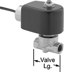
- For Use With: Liquid Argon, Liquid Nitrogen, Liquid Oxygen
- Seal Material: PTFE Plastic
| Pipe Size | Gender | Thread Type | Flow Coefficient (Cv) | Max. Pressure | Pressure Drop | Temp. Range, °F | Valve Lg. | O'all Ht. | Environmental Rating | Each | |
Normally Closed—120V AC | |||||||||||
|---|---|---|---|---|---|---|---|---|---|---|---|
| 1/4 | Female | NPT | 0.7 | 120 psi @ 70° F | Zero Pressure Drop | -320° to 355° | 1 3/4" | 3 1/8" | IP50, NEMA 2 | 00000000 | 0000000 |
| 3/8 | Female | NPT | 3.5 | 125 psi @ 70° F | Pressure Drop Assisted | -320° to 355° | 2 1/2" | 4 7/8" | IP50, NEMA 2 | 00000000 | 000000 |
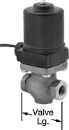
- For Use With: Liquid Argon, Liquid Nitrogen, Liquid Oxygen
- Seal Material: Glass-Filled PTFE Plastic
| Pipe Size | Gender | Thread Type | Flow Coefficient (Cv) | Max. Pressure | Pressure Drop | Temp. Range, °F | Valve Lg. | O'all Ht. | Each | |
Normally Closed—24V AC | ||||||||||
|---|---|---|---|---|---|---|---|---|---|---|
| 1/2 | Female | NPT | 3.5 | 110 psi @ -350° F | Zero Pressure Drop | -350° to 400° | 3 1/4" | 7" | 0000000 | 0000000 |
| 3/4 | Female | NPT | 7.5 | 110 psi @ -350° F | Zero Pressure Drop | -350° to 400° | 3 1/2" | 7 1/8" | 0000000 | 000000 |
| 1 | Female | NPT | 13 | 110 psi @ -350° F | Zero Pressure Drop | -350° to 400° | 4 1/8" | 8" | 0000000 | 000000 |
Normally Closed—24V DC | ||||||||||
| 1/2 | Female | NPT | 3.5 | 110 psi @ -350° F | Zero Pressure Drop | -350° to 400° | 3 1/4" | 7" | 0000000 | 000000 |
| 1 | Female | NPT | 13 | 110 psi @ -350° F | Zero Pressure Drop | -350° to 400° | 4 1/8" | 8" | 0000000 | 000000 |
Normally Closed—120V AC | ||||||||||
| 1/2 | Female | NPT | 3.5 | 110 psi @ -350° F | Zero Pressure Drop | -350° to 400° | 3 1/4" | 7 1/16" | 0000000 | 000000 |
| 1/2 | Female | NPT | 3.5 | 200 psi @ -350° F | Zero Pressure Drop | -350° to 400° | 3 1/4" | 7 1/16" | 0000000 | 000000 |
| 3/4 | Female | NPT | 7.5 | 110 psi @ -350° F | Zero Pressure Drop | -350° to 400° | 3 1/2" | 7 3/8" | 0000000 | 000000 |
| 1 | Female | NPT | 13 | 110 psi @ -350° F | Zero Pressure Drop | -350° to 400° | 4 1/8" | 8 1/8" | 0000000 | 000000 |
Extended-Life Pressure-Regulating Valves for Cryogenic Liquids
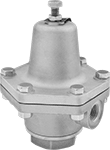
- For Use With: Liquid Argon, Liquid Carbon Dioxide, Liquid Nitrogen, Liquid Oxygen
- Temperature Range: -320° to 150° F
For a longer service life than standard valves for cryogenic liquids, these have a durable bronze body. All are cleaned and bagged for oxygen service and other high-purity applications. They automatically reduce a high, variable inlet pressure to a lower, stable outlet pressure. Adjust the outlet pressure within the range. Valves are designed to withstand the extreme cold of liquid argon, liquid carbon dioxide, liquid nitrogen, and liquid oxygen. They have an internal strainer to trap debris.
![]() For technical drawings and 3-D models, click on a part number.
For technical drawings and 3-D models, click on a part number.
Inlet | Outlet | |||||||
|---|---|---|---|---|---|---|---|---|
| Pipe Size | Location | Max. Pressure, psi | Pipe Size | Location | End-to-End Lg. | Choose an Outlet Pressure Range, psi | Each | |
NPT Female | ||||||||
Bronze Body—Bronze Diaphragm and PTFE Seal with Internal Strainer | ||||||||
| 1/4 | Side | 400 | 1/4 | Side | 3 1/16" | 00000000 | 0000000 | |
| 1/2 | Side | 400 | 1/2 | Side | 4 1/2" | 00000000 | 000000 | |
| 1 | Side | 400 | 1 | Side | 5 7/8" | 00000000 | 00000000 | |
Pressure-Regulating Valves for Cryogenic Liquids
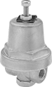
- For Use With: Liquid Argon, Liquid Carbon Dioxide, Liquid Nitrogen, Liquid Oxygen
- Temperature Range: -320° to 150° F
These valves can withstand the extreme cold of liquid argon, liquid carbon dioxide, liquid nitrogen, and liquid oxygen. All are cleaned and bagged for oxygen service and other high-purity applications. They automatically reduce a high, variable inlet pressure to a lower, stable outlet pressure. Adjust the outlet pressure within the range.
![]() For technical drawings and 3-D models, click on a part number.
For technical drawings and 3-D models, click on a part number.