


Thread Type Thread Type |
|---|
For Use With For Use With | Show |
|---|
|
For Use With For Use With | Hide |
|---|
Body Material Body Material |
|---|
|
|

Maximum Pressure Maximum Pressure |
|---|
Shape Shape |
|---|
| Straight | |
Outlet Water Flow Outlet Water Flow |
|---|
|
|
System of Measurement System of Measurement |
|---|
|
Maximum Temperature Maximum Temperature |
|---|
|
Minimum Temperature Minimum Temperature |
|---|
|
Valve Function Valve Function |
|---|
|
Overall Length Overall Length |
|---|
DFARS (Defense Acquisition Regulations Supplement) DFARS (Defense AcquisitionRegulations Supplement) |
|---|
Ball Material Ball Material |
|---|
|
RoHS (Restriction of Hazardous Substances) RoHS (Restriction ofHazardous Substances) |
|---|
|
Mounting Orientation Mounting Orientation |
|---|
|
REACH (Registration, Evaluation, Authorization and Restriction of Chemicals) REACH (Registration,Evaluation, Authorization and Restriction of Chemicals) |
|---|
|
About Backflow-Prevention Valves
More
About Actuated On/Off Valves
More
About On/Off Valves
More
How to Measure Fittings
Pipe size is an industry designation, not the actual size. View information about how to measure threaded and unthreaded pipe and pipe fittings.
More
About Precision Flow-Adjustment Valves
More
About Flanged Flow-Adjustment Valves
More
Precision Flow-Adjustment Valves with Yor-Lok Fittings for Chemicals
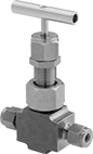
- Valve Type: Needle
- For Use With: Oil, Acetone, Air, Ammonia, Argon, Butane, Carbon Dioxide, Deionized Water, Diesel Fuel, Ethanol, Gasoline, Helium, Isopropyl Alcohol, Kerosene, Krypton, Methanol, Methyl Ethyl Ketone, Mineral Spirits, Natural Gas, Neon, Nitrogen, Oxygen, Propane, Soap Solutions, Sodium Hydroxide, Toluene, Xenon, Xylene
- Seal Material: PTFE Plastic
- Seat Material: 316 Stainless Steel
- Packing Material: PTFE Plastic
- Needle Material: 316 Stainless Steel
For extra gripping power and a strong seal, these valves have Yor-Lok fittings with two sleeves that bite into tubing as you tighten the nut. All are compatible with Swagelok®, Let-Lok, and Parker A-Lok fittings. The 316 stainless steel body, seal and needle, and the PTFE seat and packing can withstand aggressive and corrosive solutions in chemical-processing applications. Turn the handle to adjust flow in small increments for metering, sampling, and other applications requiring fine flow control. Threads and a hex nut below the handle allow you to mount these valves in instrument panels. All have a nut that can be tightened to compress the packing if it leaks. Valves have bubble-tight soft seats that provide a tight seal when the valve is completely closed.
Flow coefficient (Cv) is the amount of water (in gallons per minute) at 60° F that will flow through a fully open valve with a difference of 1 psi between the inlet and the outlet.
![]() For technical drawings and 3-D models, click on a part number.
For technical drawings and 3-D models, click on a part number.
| For Tube OD | Flow Coefficient (Cv) | Max. Pressure | Temperature Range, °F | Panel Cutout Dia. | End-to-End Lg. | Each | |
316 Stainless Steel Body | |||||||
|---|---|---|---|---|---|---|---|
Yor Lok × Yor Lok | |||||||
| 1/4" | 0.56 | 7000 psi @ 400° F | -20° to 400° | 0.87" | 2 7/8" | 0000000 | 0000000 |
| 3/8" | 0.56 | 7000 psi @ 400° F | -20° to 400° | 0.87" | 2 7/8" | 0000000 | 000000 |
| 1/2" | 0.56 | 7000 psi @ 400° F | -20° to 400° | 0.87" | 3 1/8" | 0000000 | 000000 |
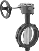
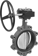
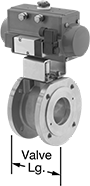
Flanged Flow-Adjustment Valves for Chemicals
With seats that can stand up to aggressive and corrosive solutions, these valves are often used in chemical-processing applications. They bolt to flanges for adjusting and regulating flow in flanged pipelines.
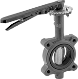
Wafer valves must be sandwiched between two flanges; they have tabs or unthreaded holes to help align the valve between the flanges.
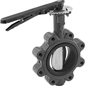
Lug valves can be sandwiched between two flanges or bolted directly to a single flange for servicing one end of the pipeline without depressurizing the other side. They have threaded flange holes with a hole pattern that matches ANSI flanges of the same pipe size.
Lockable lever handles have 10 flow-adjustment positions. The handle can be fixed in place with a padlock (not included).
Wheel handles open and close with multiple turns, providing fully adjustable flow.
Flow coefficient (Cv) is the amount of water (in gallons per minute) at 60° F that will flow through a fully open valve with a difference of 1 psi between the inlet and the outlet.
![]() For technical drawings and 3-D models, click on a part number.
For technical drawings and 3-D models, click on a part number.
- Valve Type: Butterfly
- For Use With:
Painted Ductile Iron Disc:
Air, Carbon Dioxide, Diesel Fuel, Isopropyl Alcohol, Methyl Ethyl Ketone, Nitrogen, Oxygen, Toluene
316 Stainless Steel Disc:
Food, Beverage, Carbon Dioxide, Gasoline, Liquid Carbon Dioxide, Phosphoric Acid - Seat Material: Fluoroelastomer Rubber
- Specifications Met:
Painted Ductile Iron Disc: MSS-SP-67
316 Stainless Steel Disc: API 609, MSS-SP-67, NSF/ANSI 372, NSF/ANSI 61
| Pipe Size | For Max. Shackle Dia. | Flange OD | Bolt Circle Dia. | No. of Bolt Holes | Bolt Hole Size | Bolts Included | Flow Coefficient (Cv) | Max. Pressure | Temp. Range, °F | End-to-End Lg. | Each | |
Ductile Iron Body—Painted Ductile Iron Disc | ||||||||||||
|---|---|---|---|---|---|---|---|---|---|---|---|---|
| 2 | 5/16" | 6" | 4 3/4" | 4 | 3/4" | No | 115 | 200 psi @ 275° F | 10° to 275° | 1 3/4" | 000000000 | 0000000 |
| 2 1/2 | 5/16" | 7" | 5 1/2" | 4 | 3/4" | No | 196 | 200 psi @ 275° F | 10° to 275° | 1 7/8" | 000000000 | 000000 |
| 3 | 5/16" | 7 1/2" | 6" | 4 | 3/4" | No | 302 | 200 psi @ 275° F | 10° to 275° | 1 7/8" | 000000000 | 000000 |
| 4 | 5/16" | 9" | 7 1/2" | 4 | 3/4" | No | 600 | 200 psi @ 275° F | 10° to 275° | 2 1/8" | 000000000 | 000000 |
| 5 | 5/16" | 10" | 8 1/2" | 4 | 7/8" | No | 1,022 | 200 psi @ 275° F | 10° to 275° | 2 1/4" | 000000000 | 000000 |
| 6 | 5/16" | 11" | 9 1/2" | 4 | 7/8" | No | 1,579 | 200 psi @ 275° F | 10° to 275° | 2 1/4" | 000000000 | 000000 |
- Valve Type: Butterfly
- For Use With:
Painted Ductile Iron Disc:
Air, Carbon Dioxide, Diesel Fuel, Isopropyl Alcohol, Methyl Ethyl Ketone, Nitrogen, Oxygen, Toluene
316 Stainless Steel Disc:
Food, Beverage, Carbon Dioxide, Gasoline, Liquid Carbon Dioxide, Phosphoric Acid - Seat Material: Fluoroelastomer Rubber
- Specifications Met:
Painted Ductile Iron Disc: MSS-SP-67
316 Stainless Steel Disc: API 609, MSS-SP-67, NSF/ANSI 372, NSF/ANSI 61
| Pipe Size | Flange OD | Bolt Circle Dia. | No. of Bolt Holes | Bolt Hole Size | Bolts Included | Flow Coefficient (Cv) | Max. Pressure | Temp. Range, °F | End-to-End Lg. | Each | |
Ductile Iron Body—Painted Ductile Iron Disc | |||||||||||
|---|---|---|---|---|---|---|---|---|---|---|---|
| 8 | 13 1/2" | 11 3/4" | 4 | 7/8" | No | 3,136 | 200 psi @ 275° F | 10° to 275° | 2 1/2" | 000000000 | 000000000 |
- Valve Type: Butterfly
- For Use With: See table
- Seat Material:
Ductile Iron Body: Fluoroelastomer Rubber
Cast Iron Body: PTFE-Lined Buna-N Rubber - Specifications Met:
Painted Ductile Iron Disc: MSS-SP-67
Ductile Iron Body—316 Stainless Steel Disc: API 609, MSS-SP-67, NSF/ANSI 372, NSF/ANSI 61
| Pipe Size | For Use With | For Max. Shackle Dia. | Flange OD | Bolt Circle Dia. | No. of Bolt Holes | Bolt Hole Size | Bolts Included | Flow Coefficient (Cv) | Max. Pressure | Temp. Range, °F | End-to-End Lg. | Each | |
Ductile Iron Body—Painted Ductile Iron Disc | |||||||||||||
|---|---|---|---|---|---|---|---|---|---|---|---|---|---|
| 2 | Air, Carbon Dioxide, Diesel Fuel, Isopropyl Alcohol, Methyl Ethyl Ketone, Nitrogen, Oxygen, Toluene | 5/16" | 6" | 4 3/4" | 4 | 3/4" | No | 115 | 200 psi @ 275° F | 10° to 275° | 1 3/4" | 000000000 | 0000000 |
| 2 1/2 | Air, Carbon Dioxide, Diesel Fuel, Isopropyl Alcohol, Methyl Ethyl Ketone, Nitrogen, Oxygen, Toluene | 5/16" | 7" | 5 1/2" | 4 | 3/4" | No | 196 | 200 psi @ 275° F | 10° to 275° | 1 7/8" | 000000000 | 000000 |
| 3 | Air, Carbon Dioxide, Diesel Fuel, Isopropyl Alcohol, Methyl Ethyl Ketone, Nitrogen, Oxygen, Toluene | 5/16" | 7 1/2" | 6" | 4 | 3/4" | No | 302 | 200 psi @ 275° F | 10° to 275° | 1 7/8" | 000000000 | 000000 |
| 4 | Air, Carbon Dioxide, Diesel Fuel, Isopropyl Alcohol, Methyl Ethyl Ketone, Nitrogen, Oxygen, Toluene | 5/16" | 9" | 7 1/2" | 8 | 3/4" | No | 600 | 200 psi @ 275° F | 10° to 275° | 2 1/8" | 000000000 | 000000 |
| 5 | Air, Carbon Dioxide, Diesel Fuel, Isopropyl Alcohol, Methyl Ethyl Ketone, Nitrogen, Oxygen, Toluene | 5/16" | 10" | 8 1/2" | 8 | 7/8" | No | 1,022 | 200 psi @ 275° F | 10° to 275° | 2 1/4" | 000000000 | 000000 |
| 6 | Air, Carbon Dioxide, Diesel Fuel, Isopropyl Alcohol, Methyl Ethyl Ketone, Nitrogen, Oxygen, Toluene | 5/16" | 11" | 9 1/2" | 8 | 7/8" | No | 1,579 | 200 psi @ 275° F | 10° to 275° | 2 1/4" | 000000000 | 000000 |
- Valve Type: Butterfly
- For Use With:
Painted Ductile Iron Disc:
Air, Carbon Dioxide, Diesel Fuel, Isopropyl Alcohol, Methyl Ethyl Ketone, Nitrogen, Oxygen, Toluene
316 Stainless Steel Disc:
Food, Beverage, Carbon Dioxide, Gasoline, Liquid Carbon Dioxide, Phosphoric Acid - Seat Material: Fluoroelastomer Rubber
- Specifications Met:
Painted Ductile Iron Disc: MSS-SP-67
316 Stainless Steel Disc: API 609, MSS-SP-67, NSF/ANSI 372, NSF/ANSI 61
| Pipe Size | Flange OD | Bolt Circle Dia. | No. of Bolt Holes | Bolt Hole Size | Bolts Included | Flow Coefficient (Cv) | Max. Pressure | Temp. Range, °F | End-to-End Lg. | Each | |
Ductile Iron Body—Painted Ductile Iron Disc | |||||||||||
|---|---|---|---|---|---|---|---|---|---|---|---|
| 8 | 13 1/2" | 11 3/4" | 8 | 7/8" | No | 3,136 | 200 psi @ 275° F | 10° to 275° | 2 1/2" | 000000000 | 000000000 |
Ultra-Chemical-Resistant Threaded On/Off Valves
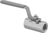
The most chemical-resistant threaded valves we offer, these have a PTFE seal and an alloy body that can withstand extremely aggressive and corrosive chemicals, such as methyl ethyl ketone and toluene. They are standard port, so they slightly restrict flow.
Monel valves are more corrosion resistant than Alloy 20 valves.
Flow coefficient (Cv) is the amount of water (in gallons per minute) at 60° F that will flow through a fully open valve with a difference of 1 psi between the inlet and the outlet.
![]() For technical drawings and 3-D models, click on a part number.
For technical drawings and 3-D models, click on a part number.
- Valve Type: Ball
- For Use With: Acetone, Air, Butane, Carbon Dioxide, Diesel Fuel, Ethanol, Ethylene Glycol, Fuel Oil, Gasoline, Kerosene, Methanol, Methyl Ethyl Ketone, Nitrogen, Propane, Soap Solutions, Sodium Hydroxide, Toluene, Water, Xylene
- Ball Material: Alloy 20 Stainless Steel
- Seal Material: PTFE Plastic
- Seat Material: PTFE Plastic
- Valve Type: Ball
- For Use With: Acetone, Air, Carbon Dioxide, Diesel Fuel, Gasoline, Kerosene, Methyl Ethyl Ketone, Nitrogen, Salt Water, Soap Solutions, Sodium Hydroxide, Toluene, Water, Xylene
- Ball Material: Monel
- Seal Material: PTFE Plastic
- Seat Material: PTFE Plastic
Easy-Maintenance Threaded On/Off Valves for Chemicals
- Valve Type: Ball
- For Use With: Carbon Dioxide, Citric Acid, Deionized Water, Ethanol, Ethylene Glycol, Hydrochloric Acid, Isopropyl Alcohol, Methanol, Methyl Ethyl Ketone, Phosphoric Acid, Salt Water, Sodium Hydroxide, Water
- Ball Material: Polypropylene Plastic
- Seal Material: Fluoroelastomer Rubber
- Seat Material: PTFE Plastic
The three-piece bolted body comes apart for access to internal components without unthreading pipe connections and removing the valve from your line. Seal is fluoroelastomer and body is polypropylene for excellent resistance to aggressive and corrosive solutions in chemical-processing applications.
Full-port valves do not restrict flow.
Standard-port valves slightly restrict flow.
![]() For technical drawings and 3-D models, click on a part number.
For technical drawings and 3-D models, click on a part number.
| Pipe Size | Max. Pressure | Temperature Range, °F | Port Type | End-to-End Lg. | Each | |
Black Polypropylene Plastic Body | ||||||
|---|---|---|---|---|---|---|
NPT Female × NPT Female | ||||||
| 1/2 | 300 psi @ 70° F | 0° to 150° | Full | 3 7/16" | 0000000 | 000000 |
| 3/4 | 300 psi @ 70° F | 0° to 150° | Full | 3 7/16" | 0000000 | 00000 |
| 1 | 225 psi @ 70° F | 0° to 150° | Standard | 3 7/16" | 0000000 | 00000 |
| 1 | 300 psi @ 70° F | 0° to 150° | Full | 4 3/16" | 0000000 | 00000 |
| 1 1/4 | 225 psi @ 70° F | 0° to 150° | Full | 4 11/16" | 0000000 | 00000 |
| 1 1/4 | 300 psi @ 70° F | 0° to 150° | Standard | 4 3/16" | 0000000 | 00000 |
| 1 1/2 | 225 psi @ 70° F | 0° to 150° | Full | 4 11/16" | 0000000 | 00000 |
| 2 | 225 psi @ 70° F | 0° to 150° | Full | 5 1/2" | 0000000 | 00000 |
| 2 | 225 psi @ 70° F | 0° to 150° | Standard | 4 11/16" | 0000000 | 00000 |
| 3 | 200 psi @ 70° F | 0° to 150° | Full | 6 3/8" | 0000000 | 000000 |
| 3 | 225 psi @ 70° F | 0° to 150° | Standard | 6 1/16" | 0000000 | 000000 |
| 4 | 100 psi @ 70° F | 0° to 150° | Standard | 7 7/8" | 0000000 | 000000 |
Flanged On/Off Valves for Chemicals
- Valve Type: Ball
- For Use With: Citric Acid, Deionized Water, Diesel Fuel, Ethanol, Ethylene Glycol, Fuel Oil, Gasoline, Hydrochloric Acid, Isopropyl Alcohol, Kerosene, Methanol, Methyl Ethyl Ketone, Mineral Spirits, Oil, Phosphoric Acid, Salt Water, Soap Solutions, Toluene, Water, Xylene
- Ball Material: Glass-Filled Vinyl Ester
- Seal Material: PTFE Plastic
- Seat Material: PTFE Plastic
- Packing Material: PTFE Plastic
- Specifications Met: ASME B16.10, ASME B16.5
Bolt these valves to ANSI flanges. A glass-filled vinyl ester body and a PTFE seal withstand aggressive and corrosive solutions in chemical-processing applications. Fix the lockable lever handle in place using a padlock (not included) with a shackle diameter up to 5/16”. All are standard port, so they slightly restrict flow.
Flow coefficient (Cv) is the amount of water (in gallons per minute) at 60° F that will flow through a fully open valve with a difference of 1 psi between the inlet and the outlet.
![]() For technical drawings and 3-D models, click on a part number.
For technical drawings and 3-D models, click on a part number.
Bolts | ||||||||||||||
|---|---|---|---|---|---|---|---|---|---|---|---|---|---|---|
| Pipe Size | Flange OD | Circle Dia. | No. of Holes | Hole Dia. | Hole Size | Included | Flow Coefficient (Cv) | Max. Pressure | Temperature Range, °F | Vacuum Rating, in. of Hg | End-to-End Lg. | For Max. Shackle Dia. | Each | |
Glass-Filled Vinyl Ester Body | ||||||||||||||
Flanged × Flanged | ||||||||||||||
| 1 | 4 1/4" | 3 1/8" | 4 | 5/8" | 0.62" | No | 45 | 250 psi @ 100° F | -50° to 215° | 29.9 | 5" | 5/16" | 0000000 | 0000000 |
| 2 | 6" | 4 3/4" | 4 | 3/4" | 0.75" | No | 165 | 250 psi @ 100° F | -50° to 215° | 29.9 | 7" | 5/16" | 0000000 | 000000 |
| 3 | 7 1/2" | 6" | 4 | 3/4" | 0.75" | No | 350 | 250 psi @ 100° F | -50° to 215° | 29.9 | 8" | 5/16" | 0000000 | 00000000 |
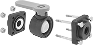
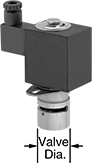
Noncontact Solenoid On/Off Valves for Chemicals
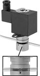
- For Use With: Water, Air, Acetone, Deionized Water, Diesel Fuel, Ethylene Glycol, Fuel Oil, Gasoline, Hydrochloric Acid, Isopropyl Alcohol, Kerosene, Methanol, Methyl Ethyl Ketone, Mineral Spirits, Sodium Hypochlorite, Sulfuric Acid, Phosphoric Acid, Sodium Hydroxide
- Specifications Met: CE Marked
For applications sensitive to contamination, these valves stop flow without contacting the process media by pressing down on the outside of tubing. They operate on electricity to automatically start and stop flow.
These valves are normally closed unless actuated. They don’t require a minimum pressure drop between the inlet and outlet for operation. The actuator is directly mounted to the valve body to minimize movement and reduce wear.
![]() For technical drawings and 3-D models, click on a part number.
For technical drawings and 3-D models, click on a part number.
For Tube | |||||||||||||
|---|---|---|---|---|---|---|---|---|---|---|---|---|---|
| OD | ID | Max. Tube Durometer | Max. Pressure | Pressure Drop | Temp. Range, °F | Valve Dia. | O'all Ht. | No. of Mounting Slots | Mounting Slot Lg. | Fasteners Included | Environmental Rating | Each | |
Anodized Aluminum Body with DIN Connection | |||||||||||||
Normally Closed—12V DC | |||||||||||||
| 1/8" | 1/16" | 50A | 10 psi @ 140° F | Zero Pressure Drop | 15° to 140° | 5/8" | 2 1/8" | 2 | 1/8" | No | IP40 | 00000000 | 0000000 |
| 3/16" | 1/8" | 50A | 10 psi @ 140° F | Zero Pressure Drop | 15° to 140° | 1" | 3 3/8" | 2 | 1/8" | No | IP65 | 00000000 | 000000 |
| 3/8" | 1/4" | 50A | 10 psi @ 140° F | Zero Pressure Drop | 15° to 140° | 1 3/16" | 4" | 2 | 1/8" | No | IP65 | 00000000 | 000000 |
Normally Closed—24V DC | |||||||||||||
| 1/8" | 1/16" | 50A | 10 psi @ 140° F | Zero Pressure Drop | 15° to 140° | 5/8" | 2 1/8" | 2 | 1/8" | No | IP40 | 00000000 | 000000 |
| 3/16" | 1/8" | 50A | 10 psi @ 140° F | Zero Pressure Drop | 15° to 140° | 1" | 3 3/8" | 2 | 1/8" | No | IP65 | 00000000 | 000000 |
| 3/8" | 1/4" | 50A | 10 psi @ 140° F | Zero Pressure Drop | 15° to 140° | 1 3/16" | 4" | 2 | 1/8" | No | IP65 | 00000000 | 000000 |
Severe-Duty Air-Driven On/Off Valves for Chemicals
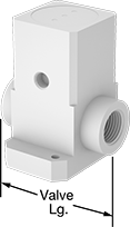
- Valve Type: Diaphragm
- For Use With:
Pipe Size 1/4: Oil, Air, Propane, Butane, Acetone, Ammonia, Carbon Dioxide, Chlorine, Deionized Water, Diesel Fuel, Ethanol, Ethylene Glycol, Fuel Oil, Gasoline, Hydrochloric Acid, Isopropyl Alcohol, Kerosene, Methanol, Methyl Ethyl Ketone, Mineral Spirits, Nitric Acid, Nitrogen, Oxygen, Sodium Hypochlorite, Sulfuric Acid, Toluene, Citric Acid, Phosphoric Acid, Sodium Hydroxide
Pipe Size 1/2: Water, Oil, Air, Natural Gas, Propane, Butane, Acetone, Ammonia, Carbon Dioxide, Chlorine, Deionized Water, Diesel Fuel, Ethanol, Ethylene Glycol, Fuel Oil, Gasoline, Hydrochloric Acid, Isopropyl Alcohol, Kerosene, Methanol, Methyl Ethyl Ketone, Mineral Spirits, Nitric Acid, Nitrogen, Oxygen, Salt Water, Soap Solutions, Sodium Hypochlorite, Steam, Sulfuric Acid, Toluene, Citric Acid, Phosphoric Acid, Sodium Hydroxide
Pipe Size 3/4: Water, Oil, Air, Natural Gas, Propane, Butane, Acetone, Ammonia, Carbon Dioxide, Chlorine, Deionized Water, Diesel Fuel, Ethanol, Ethylene Glycol, Fuel Oil, Gasoline, Hydrochloric Acid, Isopropyl Alcohol, Kerosene, Methanol, Methyl Ethyl Ketone, Mineral Spirits, Nitric Acid, Nitrogen, Oxygen, Salt Water, Soap Solutions, Sodium Hypochlorite, Steam, Sulfuric Acid, Toluene, Citric Acid, Phosphoric Acid, Sodium Hydroxide - Seal Material : PTFE Plastic
- Seat Material: PTFE Plastic
- Actuator Housing Material: Plastic
Also known as diaphragm valves, these have a PTFE body and seals that stand up to harsh acidic solutions. The diaphragm can handle dirty liquid, slurries, and abrasive media without damage. All valves operate on compressed air to automatically start and stop flow. You must control the air to the actuator using either an electric pilot valve (not included) or a manual on/off valve (not included). These valves don’t require a minimum pressure drop between the inlet and outlet for operation.
All have a single-acting actuator that only requires air pressure to open the valve; they automatically spring closed when the air turns off. The actuator is directly mounted to the valve body to minimize movement and reduce wear. Valves are normally closed unless actuated.
Flow coefficient (Cv) is the amount of water (in gallons per minute) at 60° F that will flow through a fully open valve with a difference of 1 psi between the inlet and the outlet.
![]() For technical drawings and 3-D models, click on a part number.
For technical drawings and 3-D models, click on a part number.
Air | |||||||||||||||
|---|---|---|---|---|---|---|---|---|---|---|---|---|---|---|---|
| Pipe Size | Gender | Thread Type | Flow Coefficient (Cv) | Max. Pressure | Pressure Drop | Temp. Range, °F | Valve Lg. | O'all Ht. | Connection | Pressure Range, psi | Mounting Stud Screw Size | No. of Mounting Studs | Fasteners Included | Each | |
PTFE Plastic Body | |||||||||||||||
Single Acting: Air-to-Open, Spring Return (Normally Closed) | |||||||||||||||
| 1/4 | Female | NPT | 0.7 | 60 psi @ 140° F | Zero Pressure Drop | 35° to 175° | 2 1/8" | 2 7/8" | 1/8 NPT Female | 40 to 60 | __ | 2 | No | 00000000 | 0000000 |
| 1/2 | Female | NPT | 2.8 | 60 psi @ 140° F | Zero Pressure Drop | 35° to 210° | 2 3/4" | 3 3/8" | 1/8 NPT Female | 60 to 80 | 1/4" | 2 | No | 00000000 | 000000 |
| 3/4 | Female | NPT | 7.5 | 60 psi @ 140° F | Zero Pressure Drop | 35° to 210° | 3 1/4" | 4 9/16" | 1/8 NPT Female | 60 to 80 | 1/4" | 2 | No | 00000000 | 000000 |
| Pilot Valve | 00000000 | Each | 0000000 |
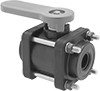
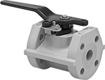
Flanged Air-Driven On/Off Valves for Chemicals
- Valve Type: Ball
- For Use With: Water, Oil, Air, Natural Gas, Propane, Butane, Acetone, Argon, Carbon Dioxide, Deionized Water, Diesel Fuel, Ethanol, Ethylene Glycol, Fuel Oil, Gasoline, Helium, Kerosene, Methanol, Methyl Ethyl Ketone, Mineral Spirits, Neon, Nitric Acid, Nitrogen, Oxygen, Salt Water, Soap Solutions, Steam, Xenon, Citric Acid, Krypton
- Ball Material: 316 Stainless Steel
- Seal Material : PTFE Plastic
- Seat Material: PTFE Plastic
- Actuator Housing Material: Aluminum
- Specifications Met: ASME B16.34
A 316 stainless steel body and a PTFE seal stand up to aggressive and corrosive solutions in chemical-processing applications. Their ball-valve design allows these valves to handle at least three times the flow of standard flanged valves. For faster actuation than motor-driven valves, they operate on compressed air. You must control the air to the actuator using either the included electric pilot valve or a manual on/off valve (not included). These valves automatically start and stop flow and don't require a minimum pressure drop between the inlet and outlet for operation.
Valves are full port, so they do not restrict flow. The actuator is secured to the valve body with a bracket for easy disassembly, maintenance, and repair. A visual flow indicator on the top of the actuator shows whether the valve is open or closed. The manual override allows you to operate the valve during power outages.
Single-acting actuators only require air pressure to open the valve; they automatically spring closed when the air turns off. These valves are normally closed unless actuated. Double-acting actuators require air pressure to open and close the valve. Once actuated, these valves remain actuated until air pressure is applied to close them, so they do not have a valve starting position.
Flow coefficient (Cv) is the amount of water (in gallons per minute) at 60° F that will flow through a fully open valve with a difference of 1 psi between the inlet and the outlet.
![]() For technical drawings and 3-D models, click on a part number.
For technical drawings and 3-D models, click on a part number.
Bolts | Air | ||||||||||||||||
|---|---|---|---|---|---|---|---|---|---|---|---|---|---|---|---|---|---|
| Pipe Size | Gender | Flange OD | No. of Holes | Hole Size | Included | Circle Dia. | Flow Coefficient (Cv) | Max. Pressure | Max. Steam Pressure | Pressure Drop | Temp. Range, °F | Valve Lg. | O'all Ht. | Connection | Pressure Range, psi | Each | |
316 Stainless Steel Body with Screw Terminals | |||||||||||||||||
Single Acting: Air-to-Open, Spring Return (Normally Closed)—120V AC | |||||||||||||||||
| 2 | Female | 6" | 4 | 5/8" | No | 4 3/4" | 307 | 275 psi @ 100° F | 100 psi @ 338° F | Zero Pressure Drop | 0° to 365° | 3 1/4" | 14 5/16" | 1/4 NPT Female | 40 to 115 | 0000000 | 000000000 |
| 3 | Female | 7" | 4 | 5/8" | No | 5 1/2" | 1,013 | 275 psi @ 100° F | 100 psi @ 338° F | Zero Pressure Drop | 0° to 365° | 4 13/16" | 18 9/16" | 1/4 NPT Female | 40 to 115 | 0000000 | 00000000 |
Double Acting: Air-to-Open, Air-to-Close—120V AC | |||||||||||||||||
| 2 | Female | 6" | 4 | 5/8" | No | 4 3/4" | 307 | 275 psi @ 100° F | 100 psi @ 338° F | Zero Pressure Drop | 0° to 365° | 3 1/4" | 13 1/4" | 1/4 NPT Female | 40 to 115 | 0000000 | 000000 |
| 3 | Female | 7" | 4 | 5/8" | No | 5 1/2" | 1,013 | 275 psi @ 100° F | 100 psi @ 338° F | Zero Pressure Drop | 0° to 365° | 4 13/16" | 14 7/16" | 1/4 NPT Female | 40 to 115 | 0000000 | 00000000 |
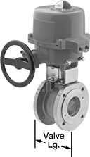
Flanged Motor-Driven On/Off Valves for Chemicals
- Valve Type: Ball
- For Use With: Water, Oil, Air, Natural Gas, Propane, Butane, Acetone, Argon, Carbon Dioxide, Deionized Water, Diesel Fuel, Ethanol, Ethylene Glycol, Fuel Oil, Gasoline, Helium, Kerosene, Methanol, Methyl Ethyl Ketone, Mineral Spirits, Neon, Nitric Acid, Nitrogen, Oxygen, Salt Water, Soap Solutions, Steam, Xenon, Citric Acid, Krypton
- Ball Material: 316 Stainless Steel
- Seal Material: PTFE Plastic
- Seat Material: PTFE Plastic
- Actuator Housing Material: Aluminum
- Specifications Met: ASME B16.34
For high-flow chemical-processing applications, these valves have a ball-valve design that provides at least three times the flow of standard flanged valves. They have a 316 stainless steel body and a PTFE seal that can stand up to aggressive and corrosive solutions. Valves operate on electricity to automatically start and stop flow. They don’t require a minimum pressure drop between the inlet and outlet for operation. All are fail in place; upon the loss of power, the valve will remain in its current position. Valves are full port, so they do not restrict flow.
The actuator is secured to the valve body with a bracket for easy disassembly, maintenance, and repair. A visual flow indicator on the top of the actuator shows whether the valve is open or closed. Two single pole, double throw (SPDT) auxiliary switches allow you to connect these valves to temperature-monitoring equipment, programmable logic controllers, or conveyor sirens. The internal heater automatically turns on when the valve is actuated to prevent motor damage caused by condensation buildup. The manual override allows you to operate the valve during power outages.
Flow coefficient (Cv) is the amount of water (in gallons per minute) at 60° F that will flow through a fully open valve with a difference of 1 psi between the inlet and the outlet.
![]() For technical drawings and 3-D models, click on a part number.
For technical drawings and 3-D models, click on a part number.
Bolts | |||||||||||||||
|---|---|---|---|---|---|---|---|---|---|---|---|---|---|---|---|
| Pipe Size | Gender | Flange OD | No. of Holes | Hole Size | Included | Circle Dia. | Flow Coefficient (Cv) | Max. Pressure | Max. Steam Pressure | Pressure Drop | Temp. Range, °F | Valve Lg. | O'all Ht. | Each | |
316 Stainless Steel Body with Screw Terminals | |||||||||||||||
Fail in Place—24V AC/24V DC | |||||||||||||||
| 2 | Female | 6" | 4 | 5/8" | No | 4 3/4" | 307 | 275 psi @ 100° F | 100 psi @ 338° F | Zero Pressure Drop | 0° to 365° | 3 1/4" | 19 1/16" | 0000000 | 000000000 |
| 3 | Female | 7 1/4" | 4 | 5/8" | No | 6" | 1,013 | 275 psi @ 100° F | 100 psi @ 338° F | Zero Pressure Drop | 0° to 365° | 4 13/16" | 22 5/8" | 0000000 | 00000000 |
Fail in Place—120V AC | |||||||||||||||
| 2 | Female | 6" | 4 | 5/8" | No | 4 3/4" | 307 | 275 psi @ 100° F | 100 psi @ 338° F | Zero Pressure Drop | 0° to 365° | 3 1/4" | 19 1/16" | 0000000 | 00000000 |
| 3 | Female | 7 1/4" | 4 | 5/8" | No | 6" | 1,013 | 275 psi @ 100° F | 100 psi @ 338° F | Zero Pressure Drop | 0° to 365° | 4 13/16" | 22 5/8" | 0000000 | 00000000 |
Ultra-Chemical-Resistant Threaded Check Valves
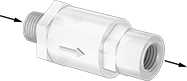
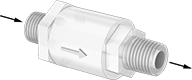
- For Use With: Acetone, Ammonia, Butane, Carbon Dioxide, Citric Acid, Diesel Fuel, Ethylene Glycol, Fuel Oil, Gasoline, Hydrochloric Acid, Isopropyl Alcohol, Kerosene, Methanol, Methyl Ethyl Ketone, Mineral Spirits, Natural Gas, Nitric Acid, Nitrogen, Oil, Oxygen, Phosphoric Acid, Propane, Salt Water, Soap Solutions, Sodium Hydroxide, Sodium Hypochlorite, Sulfuric Acid, Toluene, Water, Xylene
- Piston Material: PTFE Plastic
- Spring Material: PTFE Plastic
The most chemical-resistant check valves in our offering, these have a PFA body to withstand methyl ethyl ketone, sodium hypochlorite, and other extremely harsh chemicals. They open to allow flow in one direction and close when flow stops or reverses.
Flow coefficient (Cv) is the amount of water (in gallons per minute) at 60° F that will flow through a fully open valve with a difference of 1 psi between the inlet and the outlet.
![]() For technical drawings and 3-D models, click on a part number.
For technical drawings and 3-D models, click on a part number.
| Pipe Size | Flow Coefficient (Cv) | Max. Pressure | Min. Opening Pressure, psi | Temperature Range, °F | Color | End-to-End Lg. | Each | |
PFA Plastic Body | ||||||||
|---|---|---|---|---|---|---|---|---|
NPT Female × NPT Female | ||||||||
| 1/4 | 0.75 | 125 psi @ 150° F | 1 | 0° to 210° | White | 2 3/8" | 00000000 | 0000000 |
| 1/2 | 4 | 100 psi @ 150° F | 1 | 0° to 210° | White | 3 3/8" | 00000000 | 000000 |
NPT Female × NPT Male | ||||||||
| 1/4 | 0.75 | 125 psi @ 150° F | 1 | 0° to 210° | White | 2 7/16" | 00000000 | 000000 |
NPT Male × NPT Female | ||||||||
| 1/4 | 0.75 | 125 psi @ 150° F | 1 | 0° to 210° | White | 2 1/16" | 00000000 | 000000 |
NPT Male × NPT Male | ||||||||
| 1/4 | 0.75 | 125 psi @ 150° F | 1 | 0° to 210° | White | 2 7/16" | 00000000 | 000000 |
Flanged Check Valves for Harsh Chemicals
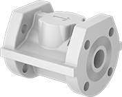
- For Use With: Ammonia, Chlorine, Citric Acid, Deionized Water, Diesel Fuel, Ethanol, Ethylene Glycol, Fuel Oil, Gasoline, Hydrochloric Acid, Isopropyl Alcohol, Kerosene, Methanol, Methyl Ethyl Ketone, Mineral Spirits, Oil, Phosphoric Acid, Salt Water, Soap Solutions, Toluene, Water, Xylene
- Ball Material: PTFE Plastic
- Seal Material: PTFE Plastic
Bolt these valves to ANSI flanges. The glass-filled vinyl body and PTFE seal stand up to a wide range of harsh chemicals. Valves open to allow flow in one direction and close when flow stops or reverses.
Flow coefficient (Cv) is the amount of water (in gallons per minute) at 60° F that will flow through a fully open valve with a difference of 1 psi between the inlet and the outlet.
| Pipe Size | Flow Coefficient (Cv) | Max. Pressure | Min. Opening Pressure, psi | Temperature Range, °F | Color | End-to-End Lg. | For Flange Class | Flange OD | Number of Bolt Holes | Bolt Hole Size | Bolt Circle Dia. | Bolts Included | Each | |
Glass-Filled Vinyl Plastic Body | ||||||||||||||
|---|---|---|---|---|---|---|---|---|---|---|---|---|---|---|
Flanged × Flanged | ||||||||||||||
| 1 | 35 | 210 psi @ 250 ° F | 1 | -40° to 250° | Beige | 5" | 150 | 4 1/4" | 4 | 5/8" | 3 1/8" | No | 000000 | 0000000 |
| 1 1/2 | 48 | 210 psi @ 250 ° F | 1 | -40° to 250° | Beige | 6 1/2" | 150 | 5" | 4 | 5/8" | 3 7/8" | No | 000000 | 000000 |
| 2 | 54 | 140 psi @ 250 ° F | 1 | -40° to 250° | Beige | 7" | 150 | 6" | 4 | 3/4" | 4 3/4" | No | 000000 | 000000 |
| 3 | 163 | 140 psi @ 250 ° F | 1 | -40° to 250° | Beige | 8" | 150 | 7 1/2" | 4 | 3/4" | 6" | No | 000000 | 00000000 |
| 4 | 288 | 110 psi @ 250 ° F | 1 | -40° to 250° | Beige | 9" | 150 | 9" | 8 | 3/4" | 7 1/2" | No | 000000 | 00000000 |
| 6 | 495 | 110 psi @ 250 ° F | 1 | -40° to 250° | Beige | 10 1/2" | 150 | 11" | 8 | 7/8" | 9 1/2" | No | 000000 | 00000000 |
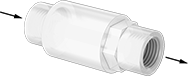
Vacuum-Breaking Valves for Chemicals
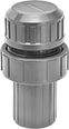
A plastic body withstands pH neutralizing, cleaning, and plating solutions containing sodium hydroxide, methyl ethyl ketone, and other harsh chemicals. Also known as vacuum breakers, these valves have vents that open when pressure drops to relieve vacuum conditions and prevent backward suction from drawing liquid into upstream piping.
![]() For technical drawings and 3-D models, click on a part number.
For technical drawings and 3-D models, click on a part number.
- For Use With: Air, Ammonia, Argon, Beverage, Carbon Dioxide, Chlorinated Water, Diesel Fuel, Drinking Water, Ethylene Glycol, Food, Helium, Hydrochloric Acid, Kerosene, Krypton, Liquid Carbon Dioxide, Methanol, Methyl Ethyl Ketone, Mineral Spirits, Natural Gas, Neon, Nitric Acid, Nitrogen, Oil, Oxygen, Soap Solutions, Sodium Hydroxide, Sodium Hypochlorite, Water, Xenon
- Diaphragm Material: Fluoroelastomer Rubber
- Seal Material: Fluoroelastomer Rubber
| Pipe Size | For Pipe Schedule | Max. Pressure | Min. Opening Pressure, psi | End-to-End Lg. | Color | Temperature Range, °F | Each | |
PVC Plastic Body | ||||||||
|---|---|---|---|---|---|---|---|---|
NPT Female × NPT Female | ||||||||
| 1/2 | 80 | 100 psi @ 75° F | 1 | 4 5/16" | Gray | 40° to 140° | 000000 | 0000000 |
| 3/4 | 80 | 100 psi @ 75° F | 1 | 4 5/8" | Gray | 40° to 140° | 0000000 | 000000 |
| 1 | 80 | 100 psi @ 75° F | 1 | 5 1/8" | Gray | 40° to 140° | 0000000 | 000000 |
CPVC Plastic Body | ||||||||
NPT Female × NPT Female | ||||||||
| 1/2 | 80 | 100 psi @ 75° F | 1 | 4 5/16" | Light Gray | 40° to 180° | 0000000 | 000000 |
| 3/4 | 80 | 100 psi @ 75° F | 1 | 4 5/8" | Light Gray | 40° to 180° | 0000000 | 000000 |
| 1 | 80 | 100 psi @ 75° F | 1 | 5 1/8" | Light Gray | 40° to 180° | 0000000 | 000000 |
- For Use With: Air, Ammonia, Argon, Beverage, Carbon Dioxide, Chlorinated Water, Diesel Fuel, Drinking Water, Ethylene Glycol, Food, Helium, Hydrochloric Acid, Kerosene, Krypton, Liquid Carbon Dioxide, Methanol, Methyl Ethyl Ketone, Mineral Spirits, Natural Gas, Neon, Nitric Acid, Nitrogen, Oil, Oxygen, Soap Solutions, Sodium Hydroxide, Sodium Hypochlorite, Water, Xenon
- Piston Material:
PVC Plastic Body: PVC Plastic
CPVC Plastic Body: CPVC Plastic - Spring Material: Plastic Polymer
- Seal Material: Fluoroelastomer Rubber
| Pipe Size | For Pipe Schedule | Max. Pressure | Min. Opening Pressure, psi | End-to-End Lg. | Color | Temperature Range, °F | Each | |
PVC Plastic Body | ||||||||
|---|---|---|---|---|---|---|---|---|
NPT Female × NPT Female | ||||||||
| 1 1/2 | 80 | 100 psi @ 75° F | 1 | 7 15/16" | Gray | 40° to 140° | 0000000 | 0000000 |
| 2 | 80 | 100 psi @ 75° F | 1 | 8 1/2" | Gray | 40° to 140° | 0000000 | 000000 |
CPVC Plastic Body | ||||||||
NPT Female × NPT Female | ||||||||
| 1 1/2 | 80 | 100 psi @ 75° F | 1 | 7 15/16" | Light Gray | 40° to 180° | 0000000 | 000000 |
| 2 | 80 | 100 psi @ 75° F | 1 | 8 1/2" | Light Gray | 40° to 180° | 0000000 | 000000 |
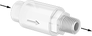
Flow-Control Orifices for Chemicals
- For Use With: Air, Ammonia, Sodium Hydroxide, Beverage, Carbon Dioxide, Diesel Fuel, Water, Oil, Ethylene Glycol, Food, Hydrochloric Acid, Kerosene, Liquid Carbon Dioxide, Methanol, Soap Solutions, Methyl Ethyl Ketone, Mineral Spirits, Natural Gas, Oxygen, Nitric Acid
- Max. Pressure: 120 psi @ 75° F
- Temperature Range: 40° to 140° F
Made of PVC, these orifices have excellent resistance to a wide range of corrosive chemicals. Also known as flow restrictors and precision orifice valves, they are used to throttle, vent, bleed, or regulate the flow of liquids and gases. They automatically adjust to changing inlet pressure to maintain consistent outlet flow.
![]() For technical drawings and 3-D models, click on a part number.
For technical drawings and 3-D models, click on a part number.
| Pipe Size | Lg. | Choose an Outlet Water Flow, gpm | Each | |
PVC Plastic Body | ||||
|---|---|---|---|---|
NPT Female × NPT Female | ||||
| 1/4 | 2 3/8" | 0000000 | 0000000 | |
| 3/8 | 2" | 0000000 | 000000 | |
| 1/2 | 2 1/4" | 0000000 | 000000 | |
| 3/4 | 3 1/4" | 3 | 0000000 | 000000 |
| 3/4 | 3 1/4" | 4 | 0000000 | 000000 |
| 3/4 | 3 1/4" | 5 | 0000000 | 000000 |
| 3/4 | 3 1/4" | 6 | 0000000 | 000000 |
| 3/4 | 3 1/4" | 7 | 0000000 | 000000 |
| 3/4 | 3 1/4" | 8 | 0000000 | 000000 |
| 3/4 | 5" | 9 | 0000000 | 000000 |
| 3/4 | 5" | 10 | 0000000 | 000000 |