


Inlet Thread Type Inlet Thread Type |
|---|
|
For Use With For Use With | Show |
|---|
|
For Use With For Use With | Hide |
|---|
Valve Type Valve Type | Show |
|---|
|
Valve Type Valve Type | Hide |
|---|
|
|
Valve Function Valve Function |
|---|
|
Actuator Style Actuator Style |
|---|
|
Outlet Thread Type Outlet Thread Type |
|---|
|
Inlet Connection Type Inlet Connection Type |
|---|
| Pipe | |
Overall Length Overall Length |
|---|
|
|
|
Overall Width Overall Width |
|---|
|
|
|
Ball Material Ball Material |
|---|
|
RoHS (Restriction of Hazardous Substances) RoHS (Restriction ofHazardous Substances) |
|---|
|
REACH (Registration, Evaluation, Authorization and Restriction of Chemicals) REACH (Registration,Evaluation, Authorization and Restriction of Chemicals) |
|---|
|
Safety-Lockout Air On/Off Valves
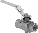
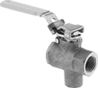
Padlocks that comply with OSHA 29 CFR 1910.147 meet standards for the control of energy sources that could injure workers.
![]() For technical drawings and 3-D models, click on a part number.
For technical drawings and 3-D models, click on a part number.
Flow Rate @ 100 psi | Overall | |||||||||||||
|---|---|---|---|---|---|---|---|---|---|---|---|---|---|---|
| Inlet Pipe Size | Outlet Pipe Size | Exhaust Pipe Size | Flow Coefficient (Cv) | Min. | Max. | Max. Pressure, psi | Temp. Range, °F | Lg. | Wd. | Ht. | For Max. Padlock Shackle Dia. | Specifications Met | Each | |
Brass Body | ||||||||||||||
| 1 1/4 | 1 1/4 | 1/4 | 86 | Not Rated | Not Rated | 200 | 32° to 210° | 8" | 2 5/16" | 4 3/4" | 9/32" | OSHA Compliant 29 CFR 1910.147 | 0000000 | 000000 |
| 1 1/2 | 1 1/2 | 1/4 | 140 | Not Rated | Not Rated | 200 | 32° to 210° | 8 3/16" | 2 13/16" | 5 1/4" | 9/32" | OSHA Compliant 29 CFR 1910.147 | 0000000 | 00000 |
| 2 | 2 | 1/4 | 190 | Not Rated | Not Rated | 200 | 32° to 210° | 8 9/16" | 3 3/8" | 5 3/4" | 9/32" | OSHA Compliant 29 CFR 1910.147 | 0000000 | 000000 |
Bronze Body | ||||||||||||||
| 1/4 | 1/4 | 1/4 | Not Rated | Not Rated | Not Rated | 200 | 50° to 200° | 4 7/8" | 1 1/16" | 3" | 1/4" | __ | 0000000 | 00000 |
| 3/8 | 3/8 | 1/4 | Not Rated | Not Rated | Not Rated | 200 | 50° to 200° | 4 7/8" | 1 1/16" | 3" | 1/4" | __ | 0000000 | 00000 |
| 1/2 | 1/2 | 1/4 | 15 | Not Rated | Not Rated | 200 | 50° to 200° | 4 15/16" | 1 3/16" | 3 1/16" | 1/4" | __ | 0000000 | 00000 |
| 3/4 | 3/4 | 1/4 | 51 | Not Rated | Not Rated | 200 | 50° to 200° | 6 7/16" | 1 13/16" | 3 11/16" | 1/4" | __ | 0000000 | 00000 |
| 1 | 1 | 1/4 | 68 | Not Rated | Not Rated | 200 | 50° to 200° | 7 5/16" | 2 1/4" | 4 3/8" | 1/4" | __ | 0000000 | 000000 |
Overall | ||||||||||||
|---|---|---|---|---|---|---|---|---|---|---|---|---|
| Inlet Pipe Size | Outlet Pipe Size | Exhaust Thread Size | Flow Coefficient (Cv) | Max. Pressure, psi | Temp. Range, °F | Lg. | Wd. | Ht. | For Max. Padlock Shackle Dia. | Specifications Met | Each | |
Brass Body | ||||||||||||
| 1/4 | 1/4 | 10-32 | 6.29 | 200 | -40° to 350° | 4 5/8" | 1 1/8" | 2 5/8" | 9/32" | OSHA Compliant 29 CFR 1910.147 | 0000000 | 000000 |
| 3/8 | 3/8 | 10-32 | 6.99 | 200 | -40° to 350° | 4 5/8" | 1 1/8" | 2 5/8" | 9/32" | OSHA Compliant 29 CFR 1910.147 | 0000000 | 00000 |
| 1/2 | 1/2 | 10-32 | 19 | 200 | -40° to 350° | 4 15/16" | 1 5/16" | 2 13/16" | 9/32" | OSHA Compliant 29 CFR 1910.147 | 0000000 | 00000 |
| 3/4 | 3/4 | 10-32 | 34.4 | 200 | -40° to 350° | 5 13/16" | 1 9/16" | 3 5/16" | 9/32" | OSHA Compliant 29 CFR 1910.147 | 0000000 | 00000 |
| 1 | 1 | 10-32 | 50.1 | 200 | -40° to 350° | 6 3/16" | 1 15/16" | 3 11/16" | 9/32" | OSHA Compliant 29 CFR 1910.147 | 0000000 | 00000 |
Air On/Off Valves
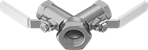
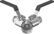
Turn airflow on and off with these valves. They have two balls to independently shut off airflow to one of two outlets from a single source. When closed, they vent air pressure to the atmosphere so you can disconnect air tools safely.
Flow coefficient (Cv) is a measurement that indicates how much airflow can pass through a valve.
![]() For technical drawings and 3-D models, click on a part number.
For technical drawings and 3-D models, click on a part number.
Number of Ports | Overall | ||||||||||
|---|---|---|---|---|---|---|---|---|---|---|---|
| Inlet | Outlet | Inlet Pipe Size | Outlet Pipe Size | Flow Coefficient (Cv) | Temp. Range, °F | Lg. | Wd. | Ht. | Ball Material | Each | |
NPT Female Inlet × NPT Female Outlet | |||||||||||
Bronze Body | |||||||||||
| 1 | 2 | 1 | 3/4 | 43 | -20° to 400° | 3 1/2" | 10" | 2 9/16" | Bronze | 0000000 | 0000000 |
| 1 | 2 | 1 1/4 | 3/4 | 43 | -20° to 400° | 3 1/2" | 10" | 2 9/16" | Bronze | 0000000 | 000000 |
NPT Female Inlet × NPT Male Outlet | |||||||||||
Brass Body | |||||||||||
| 1 | 2 | 1 | 3/4 | 30 | -40° to 365° | 5 5/8" | 8 1/8" | 2 13/16" | Chrome-Plated Brass | 0000000 | 00000 |
Timer-Operated Air On/Off Valves
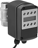
Install these valves on your air storage tank outlet—at the end of the day, they automatically close to save energy. While in the off position, the tank stays pressurized so the compressor doesn't run when you don't need it to, even if there are small leaks from pipe fittings, drip legs, and other downstream connections. Also known as solenoid valves, these valves actuate when voltage is applied to the electrical connection. They operate on a timer that can be programmed to work with a regular schedule, but they also have a manual override if your schedule changes. They gradually open to prevent system damage from suddenly starting flow.
Flow coefficient (Cv) is a measurement that indicates how much airflow can pass through a valve.
![]() For technical drawings and 3-D models, click on a part number.
For technical drawings and 3-D models, click on a part number.
Cycles | No. of Ports | Pipe Size | Overall | ||||||||||||||
|---|---|---|---|---|---|---|---|---|---|---|---|---|---|---|---|---|---|
| Max. On/Off, per Week | Timing | Flow | Inlet | Outlet | Inlet | Outlet | Flow Coefficient (Cv) | Max. Pressure, psi | Temp. Range, °F | Voltage | Electrical Connection Type | Cord Lg. | Lg. | Wd. | Ht. | Each | |
NPT Female Inlet × NPT Female Outlet | |||||||||||||||||
Brass Body with LCD Display | |||||||||||||||||
| 50 | 7 Day | 2 | 1 | 1 | 1 | 1 | 78.8 | 230 | 35° to 140° | 120V AC | Three-Prong Plug | 6 ft. | 2 15/16" | 6 3/16" | 7 5/32" | 0000000 | 0000000 |
Air Signal On/Off Valves
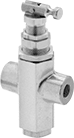
When system pressure reaches the maximum, these valves open and send an air signal to turn on a downstream device such as a discharge valve or throttle. They close and send a signal to turn the device off when pressure drops.
![]() For technical drawings and 3-D models, click on a part number.
For technical drawings and 3-D models, click on a part number.
Pressure, psi | Overall | |||||||||
|---|---|---|---|---|---|---|---|---|---|---|
| Inlet Pipe Size | Outlet Pipe Size | Min | Max. | Temp. Range, °F | Lg. | Wd. | Ht. | Ball Material | Each | |
NPT Female Inlet × NPT Female Outlet | ||||||||||
Brass Body | ||||||||||
| 1/4 | 1/8 | 95 | 125 | -15° to 400° | 1 13/16" | 15/16" | 3 1/2" | Stainless Steel | 0000000 | 000000 |
| 1/4 | 1/8 | 145 | 175 | -15° to 400° | 1 13/16" | 15/16" | 3 1/2" | Stainless Steel | 0000000 | 00000 |
| 3/8 | 1/4 | 95 | 125 | -15° to 400° | 1 1/2" | 3/8" | 5 1/4" | Stainless Steel | 0000000 | 00000 |