About Gas Regulators
More
Easy-Read Tank-Mount Pressure-Regulating
Valves with Flowmeter for Inert Gas

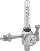
Flowmeters let you see the gas flow rate from a distance. These valves automatically reduce a high inlet pressure from compressed gas tanks to a lower, stable outlet pressure. All have Compressed Gas Association (CGA) numbered inlet fittings for secure connections to compressed gas tanks. Choose a valve with the same CGA number as your tank and other system components. They have a gauge for monitoring inlet pressure from the tank.
Single-stage valves reduce pressure in one step, which causes the outlet pressure to fluctuate slightly as you empty the tank. They’re best for applications where a constant outlet pressure isn’t critical.
Two-stage valves progressively reduce pressure over two steps for more consistent outlet pressure at all times. They’re often used in applications that require a constant outlet pressure regardless of the tank level.
Valves with one flowmeter are for one piece of equipment on a tank. The flowmeter has a single scale.
Adapters (sold separately) change 5/8"-18 outlets to 9/16"-18 male connections, and vice versa.
Inlet | Outlet | Material | ||||||||||||
|---|---|---|---|---|---|---|---|---|---|---|---|---|---|---|
| CGA Number | Location | Thread Direction | Pressure Gauge Range, psi | Stage | Thread Size | Location | Thread Direction | Flow Range, scfh | Number of Flowmeters | Body | Seal | Diaphragm | Each | |
UNF Female Outlet × NGO Male Inlet | ||||||||||||||
| CGA 580 | Side | Right Hand | 0 to 3,000 | Single | 5/8"-18 | Side | Right Hand | 0 to 70 (Argon), 0 to 70 (Argon/Carbon Dioxide Blend) | 1 | Brass | PTFE | Neoprene | 0000000 | 0000000 |
| Optional Adapter | 00000000 | Each | 000000 |
Inlet | Outlet | Material | ||||||||||||
|---|---|---|---|---|---|---|---|---|---|---|---|---|---|---|
| CGA Number | Location | Thread Direction | Pressure Gauge Range, psi | Stage | Thread Size | Location | Thread Direction | Flow Range, scfh | Number of Flowmeters | Body | Seal | Diaphragm | Each | |
UNF Female Outlet × NGO Male Inlet | ||||||||||||||
| CGA 580 | Side | Right Hand | 0 to 3,000 | Two | 5/8"-18 | Side | Right Hand | 0 to 40 (Argon), 0 to 40 (Argon/Carbon Dioxide Blend), 0 to 150 (Helium) | 1 | Brass | PTFE | Neoprene | 000000000 | 0000000 |
| Optional Adapter | 00000000 | Each | 000000 |
Inlet | Outlet | Material | ||||||||||||
|---|---|---|---|---|---|---|---|---|---|---|---|---|---|---|
| CGA Number | Location | Thread Direction | Pressure Gauge Range, psi | Stage | Thread Size | Location | Thread Direction | Flow Range, scfh | Number of Flowmeters | Body | Seal | Diaphragm | Each | |
UNF Female Outlet × NGO Male Inlet | ||||||||||||||
| CGA 580 | Side | Right Hand | 0 to 4,000 | Single | 5/8"-18 | Side | Right Hand | 0 to 60 (Argon), 0 to 60 (Argon/Carbon Dioxide Blend), 0 to 50 (Carbon Dioxide), 0 to 160 (Helium) | 1 | Brass | Buna-N | Brass | 000000000 | 0000000 |
| Optional Adapter | 00000000 | Each | 000000 |


