For Use With For Use With | Show |
---|
|
For Use With For Use With | Hide |
---|
Body Material Body Material |
---|
|
Inlet Thread Type Inlet Thread Type |
---|
|
Diaphragm Material Diaphragm Material |
---|
|
Outlet Connection Type Outlet Connection Type |
---|
![]() | Pipe |
Outlet Connection Style Outlet Connection Style |
---|
![]() |
Threaded |
Maximum Temperature Maximum Temperature |
---|
|
More
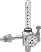
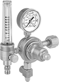
Flowmeters let you see the gas flow rate from a distance. These valves automatically reduce a high inlet pressure from compressed gas tanks to a lower, stable outlet pressure. All have Compressed Gas Association (CGA) numbered inlet fittings for secure connections to compressed gas tanks. Choose a valve with the same CGA number as your tank and other system components. They have a gauge for monitoring inlet pressure from the tank.
Single-stage valves reduce pressure in one step, which causes the outlet pressure to fluctuate slightly as you empty the tank. They’re best for applications where a constant outlet pressure isn’t critical.
Valves with one flowmeter are for one piece of equipment on a tank. The flowmeter has a single scale.
Adapters (sold separately) for valves with one flowmeter change the outlet fitting from a 5/8"-18 to 9/16"-18 male connection.
Inlet | Outlet | Material | ||||||||||||
---|---|---|---|---|---|---|---|---|---|---|---|---|---|---|
CGA Number | Location | Thread Direction | Pressure Gauge Range, psi | Stage | Thread Size | Location | Thread Direction | Flow Range, scfh | Number of Flowmeters | Body | Seal | Diaphragm | Each | |
UNF Female Outlet × NGO Male Inlet | ||||||||||||||
CGA 580 | Side | Right Hand | 0 to 4,000 | Single | 5/8"-18 | Side | Right Hand | 0 to 100 (Helium), 0 to 140 (Hydrogen) | 1 | Brass | PTFE | Neoprene | 000000000 | 0000000 |
Optional Adapter | 00000000 | Each | 00000 |
Inlet | Outlet | Material | ||||||||||||
---|---|---|---|---|---|---|---|---|---|---|---|---|---|---|
CGA Number | Location | Thread Direction | Pressure Gauge Range, psi | Stage | Thread Size | Location | Thread Direction | Flow Range, scfh | Number of Flowmeters | Body | Seal | Diaphragm | Each | |
UNF Male Outlet × NGO Female Inlet | ||||||||||||||
CGA 350 | Side | Left Hand | 0 to 3,000 | Single | 9/16"-18 | Side | Left Hand | 0 to 40 | 1 | Brass | PTFE | Neoprene | 000000000 | 0000000 |
Optional Adapter | 00000000 | Each | 00000 |
Attach these valves to acetylene, hydrogen, methane, propane, or propylene tanks to reduce a high inlet pressure to a lower, stable outlet pressure. They have Compressed Gas Association (CGA) numbered inlet fittings for secure connections to compressed gas tanks. Choose a valve with the same CGA number as your tank and other system components. Valves come with a gauge to monitor outlet pressure and a gauge to monitor inlet pressure from the tank.
Choose a valve with a maximum outlet pressure that’s approximately twice your application’s normal operating pressure. Your operating pressure should never exceed 75% of the valve’s maximum outlet pressure.
Single-stage valves reduce pressure in one step, which causes the outlet pressure to fluctuate slightly as you empty the tank. They’re best for applications where a constant outlet pressure isn’t critical.
Two-stage valves progressively reduce pressure over two steps for more consistent outlet pressure at all times. They’re often used in applications that require a constant outlet pressure regardless of the tank level.
Valves with a brass body have a longer service life than valves with a brass and steel body.
Inlet | Outlet | Material | |||||||||||
---|---|---|---|---|---|---|---|---|---|---|---|---|---|
CGA Number | Location | Thread Direction | Pressure Gauge Range, psi | Thread Size | Location | Thread Direction | Pressure Range, psi | Pressure Adjustment Method | Body | Seal | Diaphragm | Each | |
For Use With Hydrogen | |||||||||||||
UNF Male Outlet × NGO Female Inlet | |||||||||||||
CGA 350 | Side | Left Hand | 0 to 4,000 | 9/16"-18 | Side | Left Hand | 0 to 125 | T-Handle | Brass | PTFE | Rubber | 000000 | 0000000 |
Inlet | Outlet | Material | |||||||||||
---|---|---|---|---|---|---|---|---|---|---|---|---|---|
CGA Number | Location | Thread Direction | Pressure Gauge Range, psi | Thread Size | Location | Thread Direction | Pressure Range, psi | Pressure Adjustment Method | Body | Seal | Diaphragm | Each | |
For Use With Hydrogen and Methane | |||||||||||||
UNF Male Outlet × NGO Female Inlet | |||||||||||||
CGA 350 | Side | Left Hand | 0 to 4,000 | 9/16"-18 | Side | Left Hand | 2 to 40 | Knob | Brass | Neoprene | Rubber | 0000000 | 0000000 |
Install these valves directly in gas distribution pipelines for acetylene, hydrogen, or propane. They automatically reduce a high inlet pressure to a lower, stable outlet pressure. Valves have two outlets to fit various pipe configurations and come with a plug to close the unused outlet. The gauge monitors outlet pressure. All valves are single stage and reduce pressure in one step, which causes the outlet pressure to fluctuate.
Choose a valve with a maximum outlet pressure that’s approximately twice your application’s normal operating pressure. Your operating pressure should never exceed 75% of the valve’s maximum outlet pressure.
Inlet | Outlet | |||||||||||
---|---|---|---|---|---|---|---|---|---|---|---|---|
For Use With | Pipe Size | Location | Max. Pressure, psi | Pipe Size | Location | Pressure Adjustment Method | Pressure Gauge Range, psi | Temperature Range, ° F | End-to-End Lg. | Port-to-Port Lg. | Each | |
NPT Female | ||||||||||||
Brass Body—Stainless Steel Diaphragm and Neoprene Seal | ||||||||||||
Hydrogen, Propane | 1/4 | Side | 500 | 1/4 | Bottom, Side | T-Handle | 0 to 60 | 0° to 120° | 2.40" | 1.01" | 0000000 | 000000 |
Hydrogen, Propane | 1/4 | Side | 500 | 1/4 | Bottom, Side | T-Handle | 0 to 200 | 0° to 120° | 2.40" | 1.01" | 0000000 | 00000 |