


Filter by
System of Measurement
Thread Type
Flow Measurement Unit
Body Material
Maximum Temperature
Calibrated With
Mounting Position
Maximum Pressure @ Temperature
Fitting Connection
Display Type
Fitting Material
Connects To
Wetted Parts Material
Indicator Type
DFARS Specialty Metals
Export Control Classification Number (ECCN)
High-Temperature Panel-Mount Flowmeters
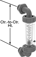 | 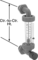 |
Male Flowmeters | Male, Flowmeters with Flow-Control Knob |
Install these flowmeters in an instrument panel to measure the flow rate of hot water and other liquids reaching up to 212° F. They should be mounted vertically, so liquid flows up from the bottom. As liquid flows through, it pushes an indicator up the scale, showing you the flow rate.
These flowmeters are calibrated with water but can be used with other liquids. If you’re using these with a liquid other than water, you’ll need to calculate the flow rate by multiplying the number shown on the scale by the specific-gravity conversion factor for your liquid.
Flow-Control Knob—Flowmeters with a flow-control knob let you open and close the inlet valve to adjust the flow rate within the range.
Flow | Temp., ° F | Flowmeters | Flowmeters with Flow-Control Knob | ||||||||||||||||||||||||||||||||||||||||||||||||||||||||||||||||||||||||||||||||||||||||||||||||
|---|---|---|---|---|---|---|---|---|---|---|---|---|---|---|---|---|---|---|---|---|---|---|---|---|---|---|---|---|---|---|---|---|---|---|---|---|---|---|---|---|---|---|---|---|---|---|---|---|---|---|---|---|---|---|---|---|---|---|---|---|---|---|---|---|---|---|---|---|---|---|---|---|---|---|---|---|---|---|---|---|---|---|---|---|---|---|---|---|---|---|---|---|---|---|---|---|---|---|---|
US Customary, gpm | Metric, L/min | Overall Ht. | Ctr.-to-Ctr. Ht. | Accuracy | Max. Pressure @ Temp. | Min. | Max. | Seal Material | Mounting Position | Each | Each | ||||||||||||||||||||||||||||||||||||||||||||||||||||||||||||||||||||||||||||||||||||||||
Polysulfone Body with Polysulfone Fittings | |||||||||||||||||||||||||||||||||||||||||||||||||||||||||||||||||||||||||||||||||||||||||||||||||||
3/8 NPT Male | |||||||||||||||||||||||||||||||||||||||||||||||||||||||||||||||||||||||||||||||||||||||||||||||||||
| 0.025 to 0.25 | 0.1 to 1 | 7" | 6" | ±4% | 175 psi @ 70° F | 33 | 212 | Fluoroelastomer | Vertical | 4215K66 | 0000000 | 4215K76 | 0000000 | ||||||||||||||||||||||||||||||||||||||||||||||||||||||||||||||||||||||||||||||||||||||
| 0.1 to 1 | 0.4 to 4 | 7" | 6" | ±4% | 175 psi @ 70° F | 33 | 212 | Fluoroelastomer | Vertical | 4215K67 | 000000 | 4215K77 | 000000 | ||||||||||||||||||||||||||||||||||||||||||||||||||||||||||||||||||||||||||||||||||||||
| 0.2 to 2 | 0.75 to 7.5 | 7" | 6" | ±4% | 175 psi @ 70° F | 33 | 212 | Fluoroelastomer | Vertical | 4215K68 | 000000 | 4215K78 | 000000 | ||||||||||||||||||||||||||||||||||||||||||||||||||||||||||||||||||||||||||||||||||||||
| 0.5 to 5 | 1.8 to 18 | 7" | 6" | ±4% | 175 psi @ 70° F | 33 | 212 | Fluoroelastomer | Vertical | 4215K69 | 000000 | 4215K79 | 000000 | ||||||||||||||||||||||||||||||||||||||||||||||||||||||||||||||||||||||||||||||||||||||
1/2 NPT Male | |||||||||||||||||||||||||||||||||||||||||||||||||||||||||||||||||||||||||||||||||||||||||||||||||||
| 0.025 to 0.25 | 0.1 to 1 | 7" | 6" | ±4% | 175 psi @ 70° F | 33 | 212 | Fluoroelastomer | Vertical | 4215K61 | 000000 | 4215K71 | 000000 | ||||||||||||||||||||||||||||||||||||||||||||||||||||||||||||||||||||||||||||||||||||||
| 0.1 to 1 | 0.4 to 4 | 7" | 6" | ±4% | 175 psi @ 70° F | 33 | 212 | Fluoroelastomer | Vertical | 4215K62 | 000000 | 4215K72 | 000000 | ||||||||||||||||||||||||||||||||||||||||||||||||||||||||||||||||||||||||||||||||||||||
| 0.2 to 2 | 0.75 to 7.5 | 7" | 6" | ±4% | 175 psi @ 70° F | 33 | 212 | Fluoroelastomer | Vertical | 4215K63 | 000000 | 4215K73 | 000000 | ||||||||||||||||||||||||||||||||||||||||||||||||||||||||||||||||||||||||||||||||||||||
| 0.5 to 5 | 1.8 to 18 | 7" | 6" | ±4% | 175 psi @ 70° F | 33 | 212 | Fluoroelastomer | Vertical | 4215K64 | 000000 | 4215K74 | 000000 | ||||||||||||||||||||||||||||||||||||||||||||||||||||||||||||||||||||||||||||||||||||||
3/4 NPT Male | |||||||||||||||||||||||||||||||||||||||||||||||||||||||||||||||||||||||||||||||||||||||||||||||||||
| 1 to 10 | 5 to 37.5 | 8" | 6 13/16" | ±4% | 175 psi @ 70° F | 33 | 212 | Fluoroelastomer | Vertical | 4215K65 | 000000 | 4215K75 | 000000 | ||||||||||||||||||||||||||||||||||||||||||||||||||||||||||||||||||||||||||||||||||||||
Panel-Mount Flow Sights for Water, Oil, and Inert Gas
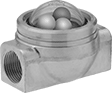 |
The included mounting ring lets you install these sights in instrument panels. They have three ball indicators that bounce in the domed-top window to show flow in your line.
Flow Sights | Repair Kits | ||||||||||||||||||||||||||||||||||||||||||||||||||||||||||||||||||||||||||||||||||||||||||||||||||
|---|---|---|---|---|---|---|---|---|---|---|---|---|---|---|---|---|---|---|---|---|---|---|---|---|---|---|---|---|---|---|---|---|---|---|---|---|---|---|---|---|---|---|---|---|---|---|---|---|---|---|---|---|---|---|---|---|---|---|---|---|---|---|---|---|---|---|---|---|---|---|---|---|---|---|---|---|---|---|---|---|---|---|---|---|---|---|---|---|---|---|---|---|---|---|---|---|---|---|---|
Window | Indicator | ||||||||||||||||||||||||||||||||||||||||||||||||||||||||||||||||||||||||||||||||||||||||||||||||||
Pipe Size | Thread Type | Gender | Temp. Range, ° F | Dia. | Type | End-to-End Lg. | Ht. | Max. Pressure @ Temp. | Panel Cutout Dia. | Direction of Flow | No. of | Material | For Use With | Each | Each | ||||||||||||||||||||||||||||||||||||||||||||||||||||||||||||||||||||||||||||||||||||
Ball Indicator | |||||||||||||||||||||||||||||||||||||||||||||||||||||||||||||||||||||||||||||||||||||||||||||||||||
Brass Body | |||||||||||||||||||||||||||||||||||||||||||||||||||||||||||||||||||||||||||||||||||||||||||||||||||
| 1/4 | NPT | Female | 35 to 120 | 1 5/8" | Domed Top | 3 1/8" | 2 1/8" | 150 psi @ 70° F | 2 3/8" | Bottom to Top, Left to Right, Right to Left, Top to Bottom | 3 | White Polyethylene White Polyethylene Green Acrylic Plastic | Water, Oil, Inert Gas | 4202K12 | 0000000 | 4202K216 | 000000 | ||||||||||||||||||||||||||||||||||||||||||||||||||||||||||||||||||||||||||||||||||
| 3/8 | NPT | Female | 35 to 120 | 1 5/8" | Domed Top | 3 1/8" | 2 1/8" | 150 psi @ 70° F | 2 3/8" | Bottom to Top, Left to Right, Right to Left, Top to Bottom | 3 | White Polyethylene White Polyethylene Green Acrylic Plastic | Water, Oil, Inert Gas | 4202K14 | 000000 | 4202K216 | 00000 | ||||||||||||||||||||||||||||||||||||||||||||||||||||||||||||||||||||||||||||||||||
| 1/2 | NPT | Female | 35 to 120 | 1 5/8" | Domed Top | 3 1/8" | 2 1/8" | 150 psi @ 70° F | 2 3/8" | Bottom to Top, Left to Right, Right to Left, Top to Bottom | 3 | White Polyethylene White Polyethylene Green Acrylic Plastic | Water, Oil, Inert Gas | 4202K16 | 000000 | 4202K216 | 00000 | ||||||||||||||||||||||||||||||||||||||||||||||||||||||||||||||||||||||||||||||||||
| 3/4 | NPT | Female | 35 to 120 | 1 5/8" | Domed Top | 3 1/8" | 2 1/8" | 150 psi @ 70° F | 2 3/8" | Bottom to Top, Left to Right, Right to Left, Top to Bottom | 3 | White Polyethylene White Polyethylene Green Acrylic Plastic | Water, Oil, Inert Gas | 4202K18 | 000000 | 4202K552 | 00000 | ||||||||||||||||||||||||||||||||||||||||||||||||||||||||||||||||||||||||||||||||||
| 1 | NPT | Female | 35 to 120 | 1 5/8" | Domed Top | 3 1/8" | 2 5/8" | 150 psi @ 70° F | 2 3/8" | Bottom to Top, Left to Right, Right to Left, Top to Bottom | 3 | White Polyethylene White Polyethylene Green Acrylic Plastic | Water, Oil, Inert Gas | 4202K19 | 000000 | 4202K552 | 00000 | ||||||||||||||||||||||||||||||||||||||||||||||||||||||||||||||||||||||||||||||||||
