


Screen Material Screen Material |
|---|
|
For Use With For Use With |
|---|
|
Connection Style Connection Style |
|---|
 |
| Threaded |
 |
| Socket Connect |
Diameter Diameter |
|---|
|
|
|
Height Height |
|---|
|
|
|
For Air Cylinder Type For Air Cylinder Type |
|---|
|
DFARS (Defense Acquisition Regulations Supplement) DFARS (Defense AcquisitionRegulations Supplement) |
|---|
REACH (Registration, Evaluation, Authorization and Restriction of Chemicals) REACH (Registration,Evaluation, Authorization and Restriction of Chemicals) |
|---|
|
RoHS (Restriction of Hazardous Substances) RoHS (Restriction ofHazardous Substances) |
|---|
|
Gasket Material Gasket Material |
|---|
|
Matching Flow Diagrams to Replace an Air Directional Control Valve
More
Choosing an Air Directional Control Valve
More
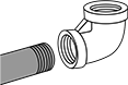
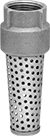
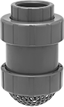
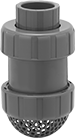
Suction Strainers with Backflow-Prevention Valve
- For Use With:
Bronze Connection: Water
Iron Connection: Water and Oil
PVC Connection: Water, Oil, and Diesel Fuel - Max. Pressure:
Bronze Connection: 400 psi
Iron Connection: 10 psi
PVC Connection: 150 psi - Temp. Range:
Bronze Connection: 32° to 190° F
Iron Connection: 32° to 150° F
PVC Connection: 40° to 140° F
Also known as foot valves, these strainers stop particles from entering your line while preventing backward flow. They are commonly used with reservoirs and tanks.
Strainers with bronze or PVC connection have better corrosion resistance than strainers with an iron connection; bronze strainers are often used in water-delivery applications.
Strainers with two union end connections allow for easy access to your line; they come with either two threaded pipe connections or one socket-connect pipe connection and one threaded pipe connection.
Strainers with socket-connect pipe connection attach to unthreaded pipe with cement for a permanent, leak-tight connection.
Strainers with male and female threaded pipe connection have threads on the outside and inside of the fitting for connecting to either male or female threaded pipe.
![]() For technical drawings and 3-D models, click on a part number.
For technical drawings and 3-D models, click on a part number.
Threaded Pipe
Connection
| Pipe Size | Thread Type | Ht. | Dia. | Gasket Material | Screen Material | Screen Opening Size | Each | |
| 3/4 | NPT | 3 3/4" | 1 3/8" | Buna-N Rubber | 430 Stainless Steel | 7/64" | 00000000 | 000000 |
| 1 | NPT | 4 3/4" | 1 3/4" | Buna-N Rubber | 430 Stainless Steel | 7/64" | 00000000 | 00000 |
| 1 1/4 | NPT | 5" | 2 1/16" | Buna-N Rubber | 430 Stainless Steel | 7/64" | 00000000 | 00000 |
| 1 1/2 | NPT | 6 5/16" | 2 5/8" | Buna-N Rubber | 430 Stainless Steel | 7/64" | 00000000 | 00000 |
| 2 | NPT | 7 3/16" | 3 1/2" | Buna-N Rubber | 430 Stainless Steel | 7/64" | 00000000 | 000000 |
| 3 | NPT | 9 1/2" | 4 5/8" | Buna-N Rubber | 430 Stainless Steel | 7/64" | 00000000 | 000000 |
Female Threaded
Pipe Connection
Female Pipe Connection | Male Pipe Connection | |||||||||
|---|---|---|---|---|---|---|---|---|---|---|
| Pipe Size | Thread Type | Pipe Size | Thread Type | Ht. | Dia. | Gasket Material | Screen Material | Screen Opening Size | Each | |
| 3/4 | NPT | 1 | NPT | 3 3/4" | 1 5/16" | Buna-N Rubber | 430 Stainless Steel | 7/64" | 00000000 | 000000 |
| 1 | NPT | 1 1/4 | NPT | 5" | 1 5/8" | Buna-N Rubber | 430 Stainless Steel | 7/64" | 00000000 | 00000 |
| 1 1/4 | NPT | 1 1/2 | NPT | 5" | 1 15/16" | Buna-N Rubber | 430 Stainless Steel | 7/64" | 00000000 | 00000 |
Strainers | Replacement Flappers | |||||||||
|---|---|---|---|---|---|---|---|---|---|---|
| Pipe Size | Thread Type | Ht. | Dia. | Flapper Material | Screen Material | Screen Opening Size | Each | Each | ||
| 1 1/2 | NPT | 4 1/8" | 4 5/8" | Leather | Iron | 5/16" | 00000000 | 0000000 | 0000000 | 000000 |
| 2 | NPT | 5 1/4" | 5 3/8" | Leather | Iron | 5/16" | 00000000 | 000000 | 0000000 | 00000 |
| 3 | NPT | 7 3/16" | 7 5/8" | Leather | Iron | 5/16" | 00000000 | 000000 | 0000000 | 00000 |
| 4 | NPT | 8 7/8" | 9 1/16" | Leather | Iron | 5/16" | 00000000 | 000000 | 0000000 | 00000 |
| 6 | NPT | 12" | 11 7/16" | Leather | Iron | 5/16" | 00000000 | 000000 | 0000000 | 000000 |
Threaded Pipe
Connection
Strainers | Replacement Screens | ||||||||||||
|---|---|---|---|---|---|---|---|---|---|---|---|---|---|
| Pipe Size | Thread Type | Ht. | Dia. | Gasket Material | Screen Material | Screen OD | Screen Lg. | Features | Screen Opening Size | Each | Each | ||
| 3 | NPT | 11 1/4" | 6 9/16" | Fluoroelastomer Rubber | PVC Plastic | 6 35/64" | 2 1/2" | Two Union End Connections | 3/16" | 00000000 | 0000000 | 0000000 | 0000000 |
| 4 | NPT | 14 5/8" | 8 9/16" | Fluoroelastomer Rubber | PVC Plastic | 8 35/64" | 4 1/4" | Two Union End Connections | 3/16" | 00000000 | 000000 | 0000000 | 000000 |
and Socket-Connect
Pipe Connection
Strainers | |||||||||||||||
|---|---|---|---|---|---|---|---|---|---|---|---|---|---|---|---|
Threaded Pipe Connection | Socket-Connect Pipe Connection | Replacement Screens | |||||||||||||
| Pipe Size | Thread Type | Pipe Size | Type | Ht. | Dia. | Gasket Material | Screen Material | Screen OD | Screen Lg. | Features | Screen Opening Size | Each | Each | ||
| 1/2 | NPT | 1/2 | Cement | 4 7/8" | 2 1/4" | Fluoroelastomer Rubber | PVC Plastic | 2 1/4" | 2 5/16" | Two Union End Connections | 3/16" | 00000000 | 0000000 | 0000000 | 000000 |
| 3/4 | NPT | 3/4 | Cement | 5" | 2 5/8" | Fluoroelastomer Rubber | PVC Plastic | 2 5/8" | 2 19/32" | Two Union End Connections | 3/16" | 00000000 | 000000 | 0000000 | 00000 |
| 1 | NPT | 1 | Cement | 5 7/8" | 3" | Fluoroelastomer Rubber | PVC Plastic | 3" | 2 7/8" | Two Union End Connections | 3/16" | 00000000 | 000000 | 0000000 | 000000 |
| 1 1/4 | NPT | 1 1/4 | Cement | 6 15/16" | 4" | Fluoroelastomer Rubber | PVC Plastic | 4" | 3 3/4" | Two Union End Connections | 3/16" | 00000000 | 000000 | 0000000 | 000000 |
| 1 1/2 | NPT | 1 1/2 | Cement | 7 1/16" | 4" | Fluoroelastomer Rubber | PVC Plastic | 4" | 3 3/4" | Two Union End Connections | 3/16" | 00000000 | 000000 | 0000000 | 000000 |
| 2 | NPT | 2 | Cement | 8 9/16" | 4 3/4" | Fluoroelastomer Rubber | PVC Plastic | 4 3/4" | 4 1/2" | Two Union End Connections | 3/16" | 00000000 | 000000 | 0000000 | 000000 |
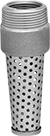
Cut-to-Size Suction Strainers with Backflow-Prevention Valve
- For Use With: Water
- Temp. Range: 32° to 180° F
A convenient replacement part to keep on hand, this strainer has NPT male threads for a variety of pipe sizes. Use a hacksaw to remove the pipe sizes that are smaller than you need. Also known as a foot valve, this strainer stops particles from entering your line while preventing backward flow. It is commonly used with reservoirs and tanks. It has an acetal connection, which is corrosion resistant and lightweight.
![]() For technical drawings and 3-D models, click on a part number.
For technical drawings and 3-D models, click on a part number.
| Pipe Size | Thread Type | Gender | Ht. | Dia. | Connection Material | Screen Material | Screen Opening Size | Each | |
| 3/4, 1, 1 1/4, 1 1/2 | NPT | Male | 7" | 1 15/16" | Acetal Plastic | Acetal Plastic | 3/32" | 00000000 | 000000 |
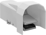
Two-Action Foot-Operated Air Directional Control Valves

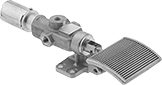
Also known as 4-way and 4/2 valves, these valves create two actions, such as extending and then retracting a cylinder. Use your foot to operate them, leaving your hands free to perform other tasks. Valves direct airflow from the inlet to your equipment and exhaust return airflow to create motion. Valves without an exhaust connection exhaust air to the atmosphere.
Valves with spring return actuation return to their original position as soon you release the actuator.
Valves with a foot return actuation stay actuated and return to their original position only when you step on them again.
Optional safety guards prevent accidental valve actuation.
Flow coefficient (Cv) is a measurement that indicates how much airflow can pass through a valve.
![]() For technical drawings and 3-D models, click on a part number.
For technical drawings and 3-D models, click on a part number.
Valves | ||||||||||||||||||
|---|---|---|---|---|---|---|---|---|---|---|---|---|---|---|---|---|---|---|
O'all | Optional Safety Guards | Replacement Seal Kits | ||||||||||||||||
| No. of Flow Ports | Inlet Size | Outlet Size | Exhaust Connection Type | Max. Flow Rate, scfm @ 100 psi | Flow Coefficient (Cv) | Pressure Range, psi | Vacuum Rating, in. of Hg | Lg. | Wd. | Ht. | Mounting Fasteners Included | Each | Each | Each | ||||
Threaded Female Inlet × Threaded Female Outlet | ||||||||||||||||||
Spring Return Actuation | ||||||||||||||||||
| A | 4 | 1/8 NPT | 1/8 NPT | __ | 30 | 0.53 | 60-150 | Not Rated | 4 1/2" | 3 1/2" | 1 3/4" | No | 0000000 | 0000000 | 000000 | 00 | 000000 | 00 |
| B | 4 | 1/4 NPTF | 1/4 NPTF | Threaded | 83 | 2.4 | 0-225 | 29 | 11 1/2" | 3 1/2" | 2 3/4" | No | 0000000 | 000000 | 0000000 | 0000000 | 00000000 | 000000 |
| B | 4 | 3/8 NPTF | 3/8 NPTF | Threaded | 118 | 3.2 | 0-225 | 29 | 12 1/2" | 3 1/2" | 2 3/4" | No | 0000000 | 000000 | 0000000 | 000000 | 00000000 | 00000 |
| B | 4 | 1/2 NPTF | 1/2 NPTF | Threaded | 185 | 5.2 | 0-215 | 29 | 14 1/2" | 3 1/2" | 3 3/8" | No | 0000000 | 000000 | 0000000 | 000000 | 00000000 | 00000 |
Foot Return Actuation | ||||||||||||||||||
| C | 4 | 1/4 NPTF | 1/4 NPTF | Threaded | 83 | 2.4 | 0-225 | 29 | 9 1/2" | 3 1/4" | 4 1/2" | No | 0000000 | 000000 | 000000 | 00 | 00000000 | 00000 |
| C | 4 | 1/2 NPTF | 1/2 NPTF | Threaded | 185 | 5.2 | 0-215 | 29 | 12 1/8" | 3 1/4" | 4 7/8" | No | 0000000 | 000000 | 000000 | 00 | 00000000 | 00000 |
| Optional Guards for Style A Valves | 000000 | Each | 000000 |
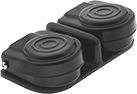
Two-Speed Two-Action Foot-Operated Air Directional Control Valves
Often used to extend and then retract a cylinder at different speeds, these valves create two actions and have two exhaust ports, which allows you to control the speed of each action by attaching a flow control valve to each exhaust port. Operate them with your foot, leaving your hands free to perform other tasks. Valves direct airflow from the inlet to your equipment and exhaust return airflow to create motion. The foot guard prevents accidental valve operation. Also known as 4-way and 5/2 valves.
Valves with spring return actuation go back to their original position as soon as you release the actuator.
Valves with a foot return actuation stay actuated and go back to their original position only when you step on them again.
Flow coefficient (Cv) is a measurement that indicates how much airflow can pass through a valve.
Overall | |||||||||||||
|---|---|---|---|---|---|---|---|---|---|---|---|---|---|
| No. of Flow Ports | Inlet Size | Outlet Size | Exhaust Connection Type | Max. Flow Rate | Flow Coefficient (Cv) | Pressure Range, psi | Vacuum Rating | Lg. | Wd. | Ht. | Mounting Fasteners Included | Each | |
Threaded Female Inlet × Threaded Female Outlet | |||||||||||||
Spring Return Actuation | |||||||||||||
| 5 | 1/4 NPT | 1/4 NPT | Threaded | Not Rated | 0.78 | 0-116 | Not Rated | 9 5/8" | 5 3/8" | 5 1/4" | No | 0000000 | 000000 |
| 5 | 1/4 BSPP | 1/4 BSPP | Threaded | 30 scfm @ 100 psi | 1.36 | 0-145 | Not Rated | 236mm | 169mm | 157mm | No | 000000 | 000000 |
Foot Return Actuation | |||||||||||||
| 5 | 1/4 BSPP | 1/4 BSPP | Threaded | 30 scfm @ 100 psi | 1.36 | 0-145 | Not Rated | 236mm | 169mm | 157mm | No | 000000 | 000000 |
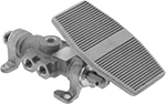
Single-Action Foot-Operated Air Directional Control Valves
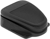
Also known as 3-way or 3/2 valves, these valves create one action, such as extending a cylinder. Use your foot to operate them, leaving your hands free to perform other tasks. Valves direct airflow from the inlet to your equipment and exhaust return airflow to create motion. They're normally closed to normally block airflow, and remain closed until actuated. Return actuation is by spring, so they go back to their original position as soon as you release the actuator. In the off position, they exhaust air pressure from the system to the atmosphere, allowing equipment to reset so the action can be repeated.
Flow coefficient (Cv) is a measurement that indicates how much airflow can pass through a valve.
![]() For technical drawings and 3-D models, click on a part number.
For technical drawings and 3-D models, click on a part number.
Valves | |||||||||||||||
|---|---|---|---|---|---|---|---|---|---|---|---|---|---|---|---|
Overall | Optional Guards for Foot Switches | ||||||||||||||
| No. of Valves | No. of Flow Ports | Inlet Size | Outlet Size | Max. Flow Rate, scfm @ 100 psi | Flow Coefficient (Cv) | Pressure Range, psi | Vacuum Rating | Lg. | Wd. | Ht. | Mounting Fasteners Included | Each | Each | ||
Threaded Female Inlet × Threaded Female Outlet | |||||||||||||||
| 1 | 3 | 1/8 NPT | 1/8 NPT | 30 | 0.53 | 60-150 | Not Rated | 2 7/8" | 2 1/2" | 1 3/8" | No | 0000000 | 000000 | 000000 | 000000 |
| 1 | 3 | 1/8 NPT | 1/8 NPT | 30 | 0.53 | 60-150 | Not Rated | 4 1/2" | 3 1/2" | 1 3/4" | No | 0000000 | 000000 | 000000 | 00000 |
| 2 | 3 | 1/8 NPT | 1/8 NPT | 30 | 0.53 | 60-150 | Not Rated | 2 7/8" | 5 3/4" | 1 1/2" | No | 0000000 | 000000 | 0000000 | 00000 |
| 2 | 3 | 1/8 NPT | 1/8 NPT | 30 | 0.53 | 60-150 | Not Rated | 4 1/2" | 8 3/8" | 1 7/8" | No | 0000000 | 000000 | 0000000 | 00000 |
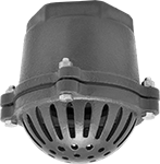
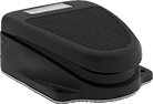
Foot-Operated Air On/Off Valves
Turn airflow on and off with your foot to keep your hands free to perform other tasks. Step on the valve to allow airflow; release the valve to stop the flow. The nonskid base prevents the valve from slipping.
Flow coefficient (Cv) is a measurement that indicates how much airflow can pass through a valve.
Optional guards prevent accidental valve actuation. Those that are 6 1/4” high can accommodate safety footwear.
![]() For technical drawings and 3-D models, click on a part number.
For technical drawings and 3-D models, click on a part number.
Flow Rate @ 100 psi | Overall | |||||||||||
|---|---|---|---|---|---|---|---|---|---|---|---|---|
| Inlet Pipe Size | Outlet Pipe Size | Flow Coefficient (Cv) | Min. | Max. | Max. Pressure, psi | Temp. Range, °F | Lg. | Wd. | Ht. | Features | Each | |
NPT Female Inlet × NPT Female Outlet | ||||||||||||
Cast Iron Body | ||||||||||||
| 1/8 | 1/8 | 0.48 | 0 scfm | 30 scfm | 150 | 0° to 130° | 4 9/16" | 3 7/16" | 1 3/4" | Nonskid Base | 0000000 | 0000000 |
Steel Body | ||||||||||||
| 1/8 | 1/8 | Not Rated | Not Rated | 30 scfm | 150 | 0° to 130° | 2 7/8" | 2 3/4" | 1 3/8" | Nonskid Base | 0000000 | 00000 |
Hands-Free Sink Faucet Control Valves
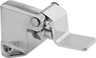
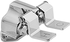

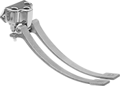
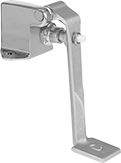
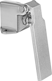
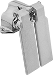
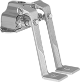
Press these valves with your foot or knee for water; release them to stop the flow. They are compliant with regulations for drinking (potable) water.
Valves with two pedals have separate controls for hot and cold. Press both to mix temperatures.
Valves | |||||||||||||||
|---|---|---|---|---|---|---|---|---|---|---|---|---|---|---|---|
Pedals | Inlet | Outlet | Replacement Pedals | ||||||||||||
| No. of | Lg. | Style | Material | Pipe Size | Thread Type | Gender | Hole Ctr.-to-Ctr. | Pipe Size | Thread Type | Gender | Mounting Hardware Included | Each | Each | ||
Floor Mount | |||||||||||||||
| 1 | 2 1/2" | Foot | Chrome-Plated Brass | 1/2 | NPT | Female | __ | 1/2 | NPT | Female | Yes | 000000 | 0000000 | 0000000 | 000000 |
| 2 | 2 1/2" | Foot | Chrome-Plated Brass | 1/2 | NPT | Female | 2 1/2" | 1/2 | NPT | Female | Yes | 000000 | 000000 | 0000000 | 00000 |
Wall Mount | |||||||||||||||
| 1 | 11 1/2" | Foot | Chrome-Plated Brass | 1/2 | NPT | Female | __ | 1/2 | NPT | Female | Yes | 000000 | 000000 | 0000000 | 00000 |
| 2 | 11 1/2" | Foot | Chrome-Plated Brass | 1/2 | NPT | Female | 2 1/2" | 1/2 | NPT | Female | Yes | 000000 | 000000 | 0000000 | 00000 |
Sink Mount | |||||||||||||||
| 1 | 6 1/2" | Knee | Chrome-Plated Brass | 1/2 | NPT | Female | __ | 1/2 | NPT | Female | Yes | 0000000 | 000000 | 0000000 | 00000 |
| 1 | 7" | Foot | Chrome-Plated Brass | 1/2 | NPT | Female | __ | 1/2 | NPT | Female | Yes | 0000000 | 000000 | 0000000 | 00000 |
| 2 | 6 1/2" | Knee | Chrome-Plated Brass | 1/2 | NPT | Female | 2 1/2" | 1/2 | NPT | Female | Yes | 0000000 | 000000 | 0000000 | 00000 |
| 2 | 7" | Foot | Chrome-Plated Brass | 1/2 | NPT | Female | 2 1/2" | 1/2 | NPT | Female | Yes | 0000000 | 000000 | 0000000 | 00000 |