


Measures Measures |
|---|
|
Force Sensor Kit Component Force Sensor Kit Component |
|---|
|
Component Component |
|---|
|
REACH (Registration, Evaluation, Authorization and Restriction of Chemicals) REACH (Registration,Evaluation, Authorization and Restriction of Chemicals) |
|---|
|
RoHS (Restriction of Hazardous Substances) RoHS (Restriction ofHazardous Substances) |
|---|
|
DFARS (Defense Acquisition Regulations Supplement) DFARS (Defense AcquisitionRegulations Supplement) |
|---|
Material Material |
|---|
|
For Operating System For Operating System |
|---|
|
For Use With For Use With |
|---|
|
|
Software Format Software Format |
|---|
|
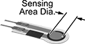
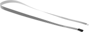
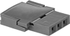
Compression Force Sensors for Tight Spaces
Thinner than a credit card, these force sensors fit into narrow spaces to measure the applied load between two surfaces. While they’re less accurate than larger alternatives such as load cells and handheld force gauges, these will fit almost anywhere. Place them within an industrial press to make sure it’s operating in a safe range, or form them to the contour of a forklift seat to test the concept of adding a smart switch that detects when an operator is sitting and ready to operate the forklift. Sensors should be calibrated before first use. Also known as force sensing resistors.
![]() For technical drawings and 3-D models, click on a part number.
For technical drawings and 3-D models, click on a part number.
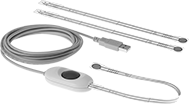
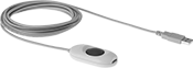
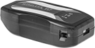
Kits come with software to analyze data from sensors. Kits with USB-A connection include a hub that plugs into your computer’s USB port. Kits with Wi-Fi connection use a hub that wirelessly connects to a computer or tablet within a sensing distance of 210 feet. The hub’s transmitter is certified 802.11b radio – 802.11b/g/n to meet IEEE standards for compatibility with other devices.
Additional sensors and hubs (both sold separately) expand the connection kits.
To connect 3-pin and 2-pin sensors into hubs with a USB connections, adapters (sold separately) are required.
Sensor | Hub | ||||||||||||||
|---|---|---|---|---|---|---|---|---|---|---|---|---|---|---|---|
| PC Connection Type | Sensor Connection Type | No. of Sensors Included | Capacity, English | Capacity, Newtons | Lg., mm | Wd., mm | Sensing Area Dia., mm | Sensing Distance, ft. | Battery Life, hrs. | No. of Batteries Included | Cord Lg., ft. | For Max. No. of Sensors | For Operating System | Each | |
| USB-A | Tab | 3 | 1 lbs. 25 lbs. 150 lbs. | 4.4 N 111 N 667 N | 229 | 14 | 9.53 | __ | __ | __ | 10 | 16 | Windows Vista Windows 7 Windows 8 Windows 8.1 Windows 10 | 0000000 | 000000000 |
| Wi-Fi | 3 Pin, 2 Pin | 3 | 1 lbs. 25 lbs. 150 lbs. | 4.4 N 111 N 667 N | 197 | 14 | 9.53 | 0-210 | 5 | 3 | __ | 16 | Windows 2000 Windows XP Windows Vista Windows 7 Windows 8 Windows 8.1 Windows 10 | 0000000 | 00000000 |
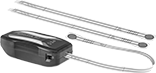
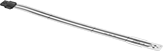
Expand your connection kit with additional sensors. Using more than one sensor allows you to monitor pressure at multiple points across a machine. Each sensor requires its own hub.
Sensors | ||||||||||||||||
|---|---|---|---|---|---|---|---|---|---|---|---|---|---|---|---|---|
Capacity | Measuring Increments | Extension Cables | ||||||||||||||
| English | Newtons | Accuracy | English | Newtons | Wd., mm | Thick., mm | Sensing Area Dia., mm | Sensing Area Lg., mm | Max. Current, mA | Input Voltage Range | Temp. Range, °F | Choose a Lg., mm | Each | Each | ||
Round—Tab Connection | ||||||||||||||||
| 1 lbs. | 4 N | ±3% | 0.1 lbs. | 0.01 N | 14 | 0.203 | 9.53 | __ | 2.5 | 0.25-1.25V DC | -40° to 140° | 229 | 0000000 | 000000 | 000000 | 00 |
| 25 lbs. | 111 N | ±3% | 0.1 lbs. | 0.01 N | 14 | 0.203 | 9.53 | __ | 2.5 | 0.25-1.25V DC | -40° to 140° | 229 | 0000000 | 00000 | 000000 | 00 |
| 150 lbs. | 667 N | ±3% | 0.1 lbs. | 0.01 N | 14 | 0.203 | 9.53 | __ | 2.5 | 0.25-1.25V DC | -40° to 140° | 229 | 0000000 | 00000 | 000000 | 00 |
Round—3-Pin Connection | ||||||||||||||||
| 1 lbs. | 4 N | ±3% | 0.1 lbs. | 0.01 N | 14 | 0.203 | 9.53 | __ | 2.5 | 0.25-1.25V DC | -40° to 140° | 000000 | 00000 | 0000000 | 000000 | |
| 25 lbs. | 111 N | ±3% | 0.1 lbs. | 0.01 N | 14 | 0.203 | 9.53 | __ | 2.5 | 0.25-1.25V DC | -40° to 140° | 000000 | 00000 | 0000000 | 00000 | |
| 50 lbs. | 222 N | ±3% | 0.1 lbs. | 0.01 N | 14 | 0.203 | 9.53 | __ | 2.5 | 0.25-1.25V DC | -40° to 400° | 000000 | 00000 | 0000000 | 00000 | |
| 100 lbs. | 445 N | ±3% | 0.1 lbs. | 0.01 N | 14 | 0.203 | 9.53 | __ | 2.5 | 0.25-1.25V DC | -40° to 140° | 000000 | 00000 | 0000000 | 00000 | |
| 150 lbs. | 667 N | ±3% | 0.1 lbs. | 0.01 N | 14 | 0.203 | 9.53 | __ | 2.5 | 0.25-1.25V DC | -40° to 140° | 191 | 0000000 | 00000 | 0000000 | 00000 |
Round—2-Pin Connection | ||||||||||||||||
| 1 lbs. | 4 N | ±3% | 0.1 lbs. | 0.01 N | 14 | 0.203 | 9.53 | __ | 2.5 | 0.25-1.25V DC | -40° to 185° | 25 | 0000000 | 00000 | 0000000 | 00000 |
| 4 lbs. | 18 N | ±3% | 0.1 lbs. | 0.01 N | 7.6 | 0.203 | 3.8 | __ | 2.5 | 0.25-1.25V DC | -40° to 140° | 16 | 0000000 | 00000 | 000000 | 00 |
| 25 lbs. | 111 N | ±3% | 0.1 lbs. | 0.01 N | 14 | 0.203 | 9.53 | __ | 2.5 | 0.25-1.25V DC | -40° to 140° | 25 | 0000000 | 00000 | 0000000 | 00000 |
| 25 lbs. | 111 N | ±3% | 0.1 lbs. | 0.01 N | 31.8 | 0.203 | 25.4 | __ | 2.5 | 0.25-1.25V DC | -40° to 140° | 25 | 0000000 | 00000 | 0000000 | 00000 |
| 100 lbs. | 445 N | ±3% | 0.1 lbs. | 0.01 N | 14 | 0.203 | 9.53 | __ | 2.5 | 0.25-1.25V DC | -40° to 140° | 25 | 0000000 | 00000 | 0000000 | 00000 |
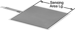
Square—2-Pin Connection | ||||||||||||||||
| 50 lbs. | 222 N | ±3% | 0.1 lbs. | 0.01 N | 55.9 | 0.203 | __ | 50.8 | 2.5 | 0.25-1.25V DC | -40° to 140° | 81 | 0000000 | 00000 | 0000000 | 00000 |
Adapters are required to connect 3-pin and 2-pin sensors into hubs with a USB connection.
Sensor Connection Type | |||
|---|---|---|---|
| Input | Output | Each | |
| 3-Pin and 2-Pin Female | Tab Male | 0000000 | 000000 |
Use male pin connectors to create a new male end on a trimmed sensor. Install a female end onto a sensor or another component with female pin connectors.
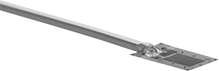
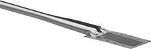
Strain Gauges
Glue these gauges onto a structure to measure strain in a single direction. They’re often used in structural testing and monitoring applications. Strain is the deformation or displacement of material caused by force.
Solder wire leads onto gauges with solder terminals after the gauge has bonded to your surface. After soldering, apply a protective coating.
Gauges with wire leads save you the effort of soldering wire to the gauge and checking to see that it’s bonded securely.
![]() For technical drawings and 3-D models, click on a part number.
For technical drawings and 3-D models, click on a part number.
Grid | Overall | ||||||||||
|---|---|---|---|---|---|---|---|---|---|---|---|
| Resistance, ohms | Accuracy | Length | Width | Length | Width | Wire Lead Length, ft. | Material | Temperature Range, °F | Pkg. Qty. | Pkg. | |
Solder Terminals | |||||||||||
For Use With Cast Iron, Composites, Printed Circuit Board, Steel | |||||||||||
| 350 | ±0.2% | 0.125" | 0.1" | 0.275" | 0.12" | __ | C70600 Copper Nickel | -100° to 350° | 5 | 0000000 | 000000 |
Two Wire Leads | |||||||||||
For Use With Aluminum, Brass, Tin | |||||||||||
| 120 | ±0.3% | 0.235" | 0.1" | 0.301" | 0.1" | 3 | C70600 Copper Nickel | -60° to 180° | 10 | 0000000 | 000000 |
| 350 | ±0.3% | 0.06" | 0.1" | 0.166" | 0.13" | 3 | C70600 Copper Nickel | -60° to 180° | 10 | 0000000 | 000000 |
| 350 | ±0.3% | 0.235" | 0.1" | 0.301" | 0.1" | 3 | C70600 Copper Nickel | -60° to 180° | 10 | 0000000 | 000000 |
For Use With Cast Iron, Composites, Printed Circuit Board, Steel | |||||||||||
| 120 | ±0.3% | 0.06" | 0.1" | 0.166" | 0.13" | 3 | C70600 Copper Nickel | -60° to 180° | 10 | 0000000 | 000000 |
| 120 | ±0.3% | 0.125" | 0.1" | 0.205" | 0.1" | 3 | C70600 Copper Nickel | -60° to 180° | 10 | 0000000 | 000000 |
| 120 | ±0.3% | 0.235" | 0.1" | 0.301" | 0.1" | 3 | C70600 Copper Nickel | -60° to 180° | 10 | 0000000 | 000000 |
| 350 | ±0.3% | 0.06" | 0.1" | 0.166" | 0.13" | 3 | C70600 Copper Nickel | -60° to 180° | 10 | 0000000 | 000000 |
| 350 | ±0.3% | 0.125" | 0.1" | 0.205" | 0.1" | 3 | C70600 Copper Nickel | -60° to 180° | 10 | 0000000 | 000000 |
For Use With Composites, Nickel Iron, Titanium Silicate | |||||||||||
| 350 | ±0.3% | 0.235" | 0.1" | 0.301" | 0.1" | 3 | C70600 Copper Nickel | -60° to 180° | 10 | 0000000 | 000000 |
Three Wire Leads | |||||||||||
For Use With Aluminum, Brass, Tin | |||||||||||
| 350 | ±0.2% | 0.03" | 0.063" | 0.095" | 0.063" | 3 | Nickel Chromium | -100° to 400° | 1 | 0000000 | 00000 |
For Use With Cast Iron, Composites, Printed Circuit Board, Steel | |||||||||||
| 350 | ±0.2% | 0.03" | 0.063" | 0.095" | 0.063" | 9 | Nickel Chromium | -100° to 400° | 1 | 0000000 | 00000 |
| 350 | ±0.3% | 0.06" | 0.1" | 0.166" | 0.13" | 9 | C70600 Copper Nickel | -60° to 180° | 10 | 0000000 | 000000 |
For Use With Composites, Nickel Iron, Titanium Silicate | |||||||||||
| 350 | ±0.3% | 0.235" | 0.1" | 0.301" | 0.1" | 9 | C70600 Copper Nickel | -60° to 180° | 10 | 0000000 | 000000 |
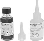
Container | |||||||||
|---|---|---|---|---|---|---|---|---|---|
| Size, fl. oz. | Type | Begins to Harden | Reaches Full Strength | Consistency (Viscosity) | Temperature Range, °F | For Use On | Includes | Each | |
| 1 | Bottle | 1 min. | 5 min. | Thin Liquid (130 cP) | -25° to 150° | Aluminum, Composites, Glass, Steel | Catalyst | 0000000 | 000000 |
| Width | Length, ft. | Color | Temperature Range | Features | Each | |
| 3/4" | 216 | Clear | 400° F | Tape Dispenser | 0000000 | 0000000 |
Dry Time | |||||
|---|---|---|---|---|---|
| Container Size, fl. oz. | Touch, min. | Overall, hrs. | Pkg. Qty. | Pkg. | |
| 1 | 20 | 2 | 4 | 0000000 | 000000 |