


Filter by
System of Measurement
Maximum Temperature
Priming Type
Maximum Flow Rate
Housing Material
Power Source
Maximum Pressure
Gear Material
Maximum Feet of Head
REACH
U.S.–Mexico–Canada Agreement (USMCA) Qualifying
DFARS Specialty Metals
Export Control Classification Number (ECCN)
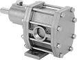
Constant-Flow-Rate Gear Pumps without Motor for Oil
 |
A cast iron housing and steel gears allow these gear pumps to be used to dispense oil and fuel such as hydraulic oil and diesel fuel. Select your own motor to tailor them to your application. Use an air or electric motor with a coupling and belt/pulley drive. They produce a smooth flow of liquid for applications such as engine lubrication. All are self-priming, which means they create a suction force to draw liquid upward and fill the pump chamber. Do not use with solids.
Note: Pumps must be filled with liquid before use. They need a constant flow of liquid and cannot run dry.
Required hp, hp | Intake (NPT) | Discharge (NPT) | Overall | Shaft | |||||||||||||||||||
|---|---|---|---|---|---|---|---|---|---|---|---|---|---|---|---|---|---|---|---|---|---|---|---|
Max. Flow Rate @ 25 psi, gpm | Max. Flow Rate | Max. ft. of Head, ft. | Max. Pressure, psi | Max. Viscosity, cP | Temp. Range, ° F | @ 25 psi | @ 100 psi | Pipe Size | Connection | Gender | Pipe Size | Connection | Gender | Lg. | Wd. | Ht. | Dia. | Lg. | Ctr.-to-Base Lg. | Each | |||
For 1,725 rpm Maximum Motor Speed | |||||||||||||||||||||||
| 8.9 | 9 gpm | 462 | 200 | 20,000 | -20 to 400 | 3/4 | 1 | 1/2 | Threaded | Female | 1/2 | Threaded | Female | 7 1/4" | 3 7/16" | 4 1/2" | 5/8" | 1 9/16" | 3" | 41915K72 | 000000000 | ||
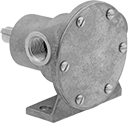
Constant-Flow-Rate Gear Pumps without Motor for Chemicals
 |
With a 316 stainless steel housing and stainless steel gears, these gear pumps are often used to dispense chemicals such as ethylene glycol, isopropyl alcohol, and nitric acid. Use an electric motor with a coupling and belt/pulley drive. They produce a smooth flow of liquid. All are self-priming, which means they create a suction force to draw liquid upward and fill the pump chamber. Do not use with solids.
Required hp, hp | Intake (NPT) | Discharge (NPT) | Overall | Shaft | |||||||||||||||||||
|---|---|---|---|---|---|---|---|---|---|---|---|---|---|---|---|---|---|---|---|---|---|---|---|
Max. Flow Rate @ 25 psi, gpm | Max. Flow Rate | Max. ft. of Head, ft. | Max. Pressure, psi | Max. Viscosity, cP | Temp. Range, ° F | @ 25 psi | @ 100 psi | Pipe Size | Connection | Gender | Pipe Size | Connection | Gender | Lg. | Wd. | Ht. | Dia. | Lg. | Ctr.-to-Base Lg. | Each | |||
For 1,800 rpm Maximum Motor Speed | |||||||||||||||||||||||
| 4.3 | 4 gpm | 346.3 | 150 | 20,000 | -50 to 450 | 1/4 | 3/4 | 1/2 | Threaded | Female | 1/2 | Threaded | Female | 6 1/4" | 3" | 3 3/4" | 1/2" | 1 1/4" | 2 5/8" | 43095K47 | 000000000 | ||
| 10.2 | 10 gpm | 346.3 | 150 | 20,000 | -50 to 450 | 1/2 | 1 1/2 | 3/4 | Threaded | Female | 3/4 | Threaded | Female | 7 1/2" | 3 3/8" | 4 3/8" | 5/8" | 1 3/4" | 3" | 43095K52 | 00000000 | ||
Self-Priming Circulation Pumps without Motor for Oil
 |
Use these pumps to move lubricating oil such as hydraulic and motor oil. Also known as flexible impeller pumps, they create a suction force that can draw liquid upward to fill the pump chamber when your liquid source is below the pump. The impeller resists clogging and wear. Select a spark-free air motor for hazardous environments or attach an electric motor with a speed reducer or a belt pulley to alter the pump speed.
Repair kits (sold separately) include components such as impellers, O-rings, and seal lips.
Note: Pumps must be filled with liquid before use. They need a constant flow of liquid and cannot run dry.
Shaft | Overall | ||||||||||||||||
|---|---|---|---|---|---|---|---|---|---|---|---|---|---|---|---|---|---|
Max. Flow Rate, gpm | Max. ft. of Head, ft. | Max. Pressure, psi | Max. Viscosity | Temp. Range, ° F | Req. Power, hp | Intake Connection Type | Discharge Connection Type | Dia. | Lg. | Ctr.-to-Base Lg. | Ht. | Lg. | Wd. | Each | |||
For 500 rpm to 2,100 rpm Motor Speed | |||||||||||||||||
| 11.5 | 50 | 21 | Not Rated | 50 to 180 | 1/3 | 1/2 Female NPT | 1/2 Female NPT | 5/8" | 1 1/8" | 1 15/16" | 3 13/16" | 4 1/2" | 4 1/8" | 4281K24 | 0000000 | ||
| 25 | 50 | 26 | Not Rated | 50 to 180 | 3/4 | 1 Female NPT | 1 Female NPT | 5/8" | 2 1/4" | 1 7/8" | 3 9/16" | 6 3/8" | 4 3/4" | 4281K26 | 000000 | ||
Air-Powered Constant-Flow-Rate Piston Pumps
 |
Commonly called piston pumps, these are often used in high-pressure applications, such as hydrostatic testing of pipelines, tanks, and valves. Flow and outlet liquid pressure can be controlled by varying the air pressure. To calculate discharge liquid pressure, multiply the air pressure by the ratio shown in the table. Pumps are self-priming, which means they create a suction force to draw liquid upward to fill the pump chamber.
Note: Pumps must be filled with liquid before use. They need a constant flow of liquid and cannot run dry.
Air Pressure, psi | Overall | |||||||||||||||
|---|---|---|---|---|---|---|---|---|---|---|---|---|---|---|---|---|
Flow Rate @ 0 psi, gpm | Max. ft. of Head, ft. | Max. Discharge Pressure, psi | Max. Viscosity, cP | Min. | Max. | Air Consumption, scfm | Air Connection (NPT) | Intake Pipe Connection (NPT) | Discharge Pipe Connection (NPT) | Lg. | Wd. | Ht. | Each | |||
11:1 Discharge Liquid to Inlet Air Pressure Ratio | ||||||||||||||||
| 4.76 | 3,679 | 1,595 | 100 | 15 | 145 | 45 | 1/2 Female | 1 Female | 1/2 Female | 10 3/4" | 9 1/2" | 10 3/8" | 6770K28 | 000000000 | ||
