Filter by
For Use With
Outlet Pressure
Maximum Inlet Pressure
Maximum Outlet Pressure Gauge Measurement
Maximum Pressure
Outlet Connection
Outlet Thread Type
Valve Function
Fitting Connection
DFARS Specialty Metals
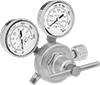
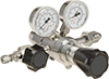
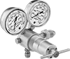
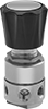
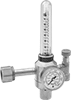
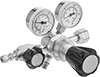
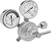
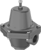
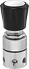
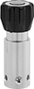
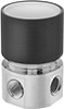
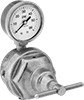
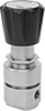
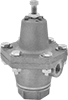
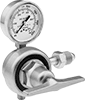
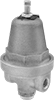
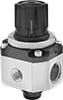
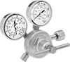
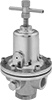
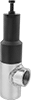
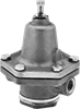
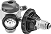
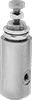
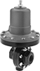
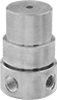
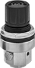
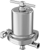
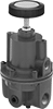
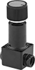
Pressure-Regulating Valves
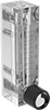
Pressure-Regulating Valves