


Filter by
System of Measurement
Body Material
Fitting Connection
Maximum Flow
Fitting Material
Wetted Parts Material
Connects To
Flow Measurement Type
Minimum Flow
Maximum Temperature
Flow Measurement Unit
DFARS Specialty Metals
Export Control Classification Number (ECCN)
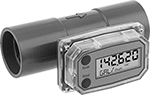
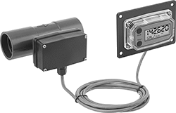
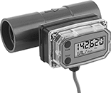
Socket-Connect Flowmeter/Totalizers with Remote Display
Tee Fittings
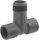 |
Tee fittings mount inline with your pipe. They have two unthreaded socket ends that bond to unthreaded PVC pipe with PVC cement and primer.
Temp., ° F | |||||||||||
|---|---|---|---|---|---|---|---|---|---|---|---|
Inlet/Outlet Connection | Sensor Connection | Pipe Schedule | Flow, gpm | Max. Pressure @ Temp. | Min. | Max. | Mounting Position | Each | |||
PVC Body | |||||||||||
| 1/2 Socket Connect Female Inlet Pipe × 1/2 Socket Connect Female Outlet Pipe | 1 1/4 NPSM Threaded Male Pipe | 80 | 1 to 18.9 | 180 psi @ 70° F | 33 | 149 | Any Angle | 4114K231 | 0000000 | ||
| 3/4 Socket Connect Female Inlet Pipe × 3/4 Socket Connect Female Outlet Pipe | 1 1/4 NPSM Threaded Male Pipe | 80 | 1.7 to 33.2 | 180 psi @ 70° F | 33 | 149 | Any Angle | 4114K232 | 000000 | ||
| 1 Socket Connect Female Inlet Pipe × 1 Socket Connect Female Outlet Pipe | 1 1/4 NPSM Threaded Male Pipe | 80 | 2.7 to 53.9 | 180 psi @ 70° F | 33 | 149 | Any Angle | 4114K233 | 000000 | ||
| 1 1/2 Socket Connect Female Inlet Pipe × 1 1/2 Socket Connect Female Outlet Pipe | 1 1/4 NPSM Threaded Male Pipe | 80 | 6.4 to 126.9 | 180 psi @ 70° F | 33 | 149 | Any Angle | 4114K235 | 000000 | ||
| 2 Socket Connect Female Inlet Pipe × 2 Socket Connect Female Outlet Pipe | 1 1/4 NPSM Threaded Male Pipe | 80 | 10.5 to 209.2 | 180 psi @ 70° F | 33 | 149 | Any Angle | 4114K236 | 000000 | ||
| 3 Socket Connect Female Inlet Pipe × 3 Socket Connect Female Outlet Pipe | 1 1/4 NPSM Threaded Male Pipe | 80 | 23 to 460.8 | 180 psi @ 70° F | 33 | 149 | Any Angle | 4114K238 | 000000 | ||
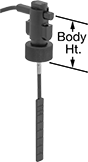
Fixed-Set-Point Insertion-Mount Flow Switches
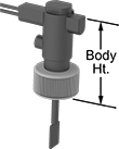 |
Easy to install, these flow switches come already set to a specific set point and don’t require you to disassemble your pipeline. Instead of mounting them inline, insert them into an unthreaded PVC pipe tee or pipe outlet in large-diameter pipe. They have a paddle that’s pushed as your liquid moves through to determine flow. When the paddle reaches a set position determined by the set point, it activates or deactivates equipment. All are single pole, double throw (SPDT) and can either turn one device from off to on (normally open) or on to off (normally closed). IP rated, they seal out dust and can be lightly rinsed.
They should be mounted vertically into a horizontal pipeline, so liquid pushes the paddle. Secure them with PVC cement and primer (not included).
These flow switches are calibrated with water. You can use them with other liquids, but they may not measure accurately if the liquid’s viscosity differs from water.
Pipe Connections | For Pipe Size | Set Point, gpm | Max. Flow Rate, gpm | Max. Pressure @ Temp. | Temp. Range, ° F | Voltage | Max. Switching Current @ Voltage | Body Ht. | Enclosure Rating | Specs. Met | Each | |||
|---|---|---|---|---|---|---|---|---|---|---|---|---|---|---|
Noryl Body with Socket-Connect PVC Fittings | ||||||||||||||
| 1/2 | 1/2 | 1.03 | 7.9 | 160 psi @ 70° F | -13 to 212 | 230V AC/48V DC | 1 amp @ 230V AC 1 amp @ 48V DC | 2 1/2" | IP65 | UL 508 | 2766K113 | 0000000 | ||
| 3/4 | 3/4 | 1.94 | 21 | 160 psi @ 70° F | -13 to 212 | 230V AC/48V DC | 1 amp @ 230V AC 1 amp @ 48V DC | 2 1/2" | IP65 | UL 508 | 2766K114 | 000000 | ||
| 3/4 | 1 1 1/4 | 2.7, 6.8 | 31, 40 | 160 psi @ 70° F | -13 to 212 | 230V AC/48V DC | 1 amp @ 230V AC 1 amp @ 48V DC | 2 1/2" | IP65 | UL 508 | 2766K115 | 000000 | ||
Hazardous-Location Insertion-Mount Flow Switches
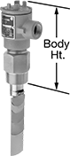 |
Safely activate and deactivate equipment in environments with flammable gases and combustible dust when your flow rate reaches a set point. They are UL listed and CSA certified for use in hazardous locations. These switches save you from disassembling your pipeline because you insert them into pipe tees or pipe outlets instead of mounting them inline. They actuate when your system’s liquid pushes the paddle into a set position. To change your set point, the paddle has multiple layers that you can remove. For the lowest set point, use the largest paddle that will fit your pipe. To increase your set point, loosen the locking washers and remove paddles. You can trim the paddles to fine-tune your set point. The smaller the paddle, the higher the setpoint.
They should be mounted vertically into a horizontal pipeline, so liquid pushes the paddle.
These switches are calibrated with water and air. They can also be used with other liquids and gases but may not measure accurately if their viscosity is significantly different.
SPDT—SPDT (singe pole, double throw) switches can turn one device from off to on (normally open) or from on to off (normally closed).
DPDT—DPDT (double pole, double throw) switches can either turn two devices from off to on (normally open) or on to off (normally closed).
Flow Set Point Range | Max. Flow Rate | Conduit | ||||||||||||||||
|---|---|---|---|---|---|---|---|---|---|---|---|---|---|---|---|---|---|---|
Pipe Size | Thread Type | Gender | For Pipe Size | For Water and Oil | For Air and Inert Gas | For Water and Oil | For Air and Inert Gas | Max. Pressure @ Temp. | Temp. Range, ° F | Max. Switching Current @ Voltage | Trade Size | Thread Type | Gender | Body Ht. | Each | |||
SPDT | ||||||||||||||||||
Brass Body | ||||||||||||||||||
| 1 1/2 | NPT | Male | 1 1/2 2 4 12 20 | 3 gpm to 7 gpm 4 gpm to 15 gpm 12 gpm to 95 gpm 140 gpm to 900 gpm 400 gpm to 2,400 gpm | 17 scfm to 32 scfm 13 scfm to 65 scfm 50 scfm to 400 scfm 800 scfm to 3,450 scfm 2,850 scfm to 10,000 scfm | 55 gpm 97 gpm 391 gpm 3,525 gpm 9,792 gpm | Not Rated | 1,000 psi @ 70° F | -4 to 275 | 5 amp @ 125V AC 5 amp @ 250V AC | 3/4 | NPT | Female | 8" | 48005K53 | 0000000 | ||
316 Stainless Steel Body | ||||||||||||||||||
| 1 1/2 | NPT | Male | 1 1/2 2 4 12 20 | 3 gpm to 7 gpm 4 gpm to 15 gpm 12 gpm to 95 gpm 140 gpm to 900 gpm 400 gpm to 2,400 gpm | 17 scfm to 32 scfm 13 scfm to 65 scfm 50 scfm to 400 scfm 800 scfm to 3,450 scfm 2,850 scfm to 10,000 scfm | 55 gpm 97 gpm 391 gpm 3,525 gpm 9,792 gpm | Not Rated | 2,000 psi @ 70° F | -4 to 275 | 5 amp @ 125V AC 5 amp @ 250V AC | 3/4 | NPT | Female | 8" | 48005K55 | 00000000 | ||
DPDT | ||||||||||||||||||
Brass Body | ||||||||||||||||||
| 1 1/2 | NPT | Male | 1 1/2 2 4 12 20 | 3 gpm to 7 gpm 4 gpm to 15 gpm 12 gpm to 95 gpm 140 gpm to 900 gpm 400 gpm to 2,400 gpm | 17 scfm to 32 scfm 13 scfm to 65 scfm 50 scfm to 400 scfm 800 scfm to 3,450 scfm 2,850 scfm to 10,000 scfm | 55 gpm 97 gpm 391 gpm 3,525 gpm 9,792 gpm | Not Rated | 1,000 psi @ 70° F | -4 to 275 | 5 amp @ 125V AC 5 amp @ 250V AC | 3/4 | NPT | Female | 8" | 48005K54 | 000000 | ||
316 Stainless Steel Body | ||||||||||||||||||
| 1 1/2 | NPT | Male | 1 1/2 2 4 12 20 | 3 gpm to 7 gpm 4 gpm to 15 gpm 12 gpm to 95 gpm 140 gpm to 900 gpm 400 gpm to 2,400 gpm | 17 scfm to 32 scfm 13 scfm to 65 scfm 50 scfm to 400 scfm 800 scfm to 3,450 scfm 2,850 scfm to 10,000 scfm | 55 gpm 97 gpm 391 gpm 3,525 gpm 9,792 gpm | Not Rated | 2,000 psi @ 70° F | -4 to 275 | 5 amp @ 125V AC 5 amp @ 250V AC | 3/4 | NPT | Female | 8" | 48005K56 | 00000000 | ||
Socket-Connect Flowmeter/Totalizers
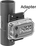 |
Shown with 90° Display Adapter Kit |
 |
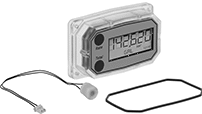 |
Replacement Displays |
The unthreaded ends of these flowmeter/totalizers install into a PVC piping system, so you can measure the flow rate and volume of liquid passing through your system. Bond the joint together with PVC cement and primer. You can reset the batch total, but you can't reset the cumulative total. They measure flow correctly no matter the mounting orientation.
These flowmeter/totalizers are calibrated with water.
Turbine Flow Measurement—Turbine flowmeter/totalizers measure flow by counting how many times their turbine turns as liquid passes through. To avoid clogging the turbine and other damage, use them only with clean, low-viscosity liquids. You can recalibrate them in the field to other liquids, pipe, and operating conditions.
Ultrasonic Flow Measurement—Ultrasonic flowmeter/totalizers measure flow with ultrasonic waves, so they don’t have internal moving parts that can break or get stuck.
Flowmeter/Totalizers | Replacement Displays | |||||||||||||||||
|---|---|---|---|---|---|---|---|---|---|---|---|---|---|---|---|---|---|---|
Flowmeter/Totalizers | ||||||||||||||||||
Max. Volume Displayed | Temp., ° F | |||||||||||||||||
Connections | Flow, gpm | Pipe Schedule | End-to-End Lg. | Accuracy | Total | Batch | Max. Pressure @ Temp. | Mounting Position | Batteries Included | Min. | Max. | Each | Display Type | Each | ||||
Turbine Flow Measurement | ||||||||||||||||||
PVC Body with PVC Fittings and 316 Stainless Steel Seal | ||||||||||||||||||
| 1/2 Male | 1 to 10 | 80 | 4 5/16" | ±3% | 999,999 Gallons | 999,999 Gallons | 225 psi @ 70° F | Any Angle | Yes | 33 | 140 | 5020T711 | 0000000 | Digital | 4352K513 | 0000000 | ||
| 3/4 Male | 2 to 20 | 80 | 4 7/16" | ±3% | 999,999 Gallons | 999,999 Gallons | 225 psi @ 70° F | Any Angle | Yes | 33 | 140 | 5020T721 | 000000 | Digital | 4352K523 | 000000 | ||
| 1 Male | 5 to 50 | 80 | 4 1/2" | ±3% | 999,999 Gallons | 999,999 Gallons | 225 psi @ 70° F | Any Angle | Yes | 33 | 140 | 5020T731 | 000000 | Digital | 4352K533 | 000000 | ||
| 1 1/2 Male | 10 to 100 | 80 | 5 3/8" | ±3% | 999,999 Gallons | 999,999 Gallons | 225 psi @ 70° F | Any Angle | Yes | 33 | 140 | 5020T741 | 000000 | Digital | 4352K543 | 000000 | ||
| 2 Male | 20 to 200 | 80 | 5 1/2" | ±3% | 999,999 Gallons | 999,999 Gallons | 225 psi @ 70° F | Any Angle | Yes | 33 | 140 | 5020T751 | 000000 | Digital | 4352K553 | 000000 | ||
Ultrasonic Flow Measurement | ||||||||||||||||||
PVC Body with PVC Fittings and EPDM Seal | ||||||||||||||||||
| 3 Male | 2.06 to 309 | 80 | 6 5/8" | ±2% | 999,999 Gallons | 999,999 Gallons | 200 psi @ 70° F | Any Angle | Yes | 32 | 140 | 3777K51 | 00000000 | Digital | 3777K615 | 000000 | ||
| 4 Male | 3.58 to 537 | 80 | 7 3/8" | ±2% | 999,999 Gallons | 999,999 Gallons | 200 psi @ 70° F | Any Angle | Yes | 32 | 140 | 3777K52 | 00000000 | Digital | 3777K625 | 000000 | ||
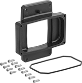 |
90° Display Adapter Kit |
90° Display Adapter—90° display adapter kits let you rotate the meter’s display 90°, so you can read it easier when mounted vertically.
Includes | For Flow Measurement Type | Each | ||
|---|---|---|---|---|
| 90° Display Adapter, 12 Screws, Nitrile Rubber O-Ring | Turbine | 4352K101 | 000000 |
 |
For Flow Measurement Type | Each | ||
|---|---|---|---|
| Turbine | 4352K221 | 0000000 |
 |
Output modules allow you to transmit flow data from flowmeter/totalizers to an external device such as a programmable logic controller (PLC), data recorder, logger, and remote display.
4-20 mA output modules have an analog output. As flow increases, the output signal from the transmitter increases. For your receiving device to interpret the signal from the transmitter, you will need to calibrate it for the measurement range and output signal of the transmitter. They only give accurate readings within the rated measurement range.
Pulse output modules have a digital output. They transmit flow data using spikes of voltage that match the input voltage of the transmitter. The higher the flow, the more pulses they send.
Output Current, mA | No. of Wire Leads | Wire Lead Lg., ft. | Input Voltage, V DC | For Flow Measurement Type | Each | ||
|---|---|---|---|---|---|---|---|
| 4 to 20 | 4 | 10 | 8 to 26 | Turbine | 4352K227 | 0000000 |
Battery Size | Battery Chemistry | Battery Cap., mA·h | Pkg. Qty. | Pkg. | |||
|---|---|---|---|---|---|---|---|
Disposable Battery | |||||||
| AAA | Alkaline | 1,250 | 4 | 71455K62 | 00000 | ||
Insertion-Mount Flow Switches
 |
Socket Connection with IP65 Rating |
Avoid complicated inline installation—these flow switches insert into a tee or pipe outlet, so you don’t need to disassemble your pipeline. They have a paddle that’s pushed as your liquid moves through to determine flow. When the paddle reaches a set position determined by the set point, it activates or deactivates equipment. They are single pole, double throw (SPDT) and can either turn one device from off to on (normally open) or on to off (normally closed). They should be mounted vertically into a large-diameter horizontal pipeline, so liquid pushes the paddle.
These flow switches are calibrated with water. You can use them with other liquids, but they may not measure accurately if the liquid’s viscosity differs from water.
Choose a fitting material that is compatible with the liquid you're running through your line.
Noryl Body—Switches with a Noryl body have a paddle that you trim to adjust the set point. The more you trim, the higher the set point.
Socket-Connect Fitting Connection—Socket-connect flow switches bond to an unthreaded PVC pipe tee or pipe outlet with PVC cement and primer (not included).
Noryl Fitting—Noryl fittings work with a wide range of chemicals.
IP65 Enclosure Rating—IP65 rated switches seal out dust and can be lightly rinsed.
For Pipe Size | Flow Set Point Range, gpm | Max. Flow Rate, gpm | Paddle Material | Max. Pressure @ Temp. | Temp. Range, ° F | Max. Switching Current @ Voltage | Body Ht. | Enclosure Rating | Specs. Met | Each | |||
|---|---|---|---|---|---|---|---|---|---|---|---|---|---|
Noryl Body with 3/4 Socket-Connect Noryl Fittings | |||||||||||||
Set-Point-Adjustment Trimmable Paddles | |||||||||||||
| 1 1/2 2 3 | 7.7 to 19.3 10.3 to 21 16.5 to 52 | 110, 150, 390 | Noryl | 160 psi @ 70° F | -13 to 212 | 1 amp @ 230V AC 1 amp @ 48V DC | 2 1/2" | IP65 | UL 508 | 2766K41 | 0000000 | ||
| 1 1/2 2 3 | 7.9 to 15 10 to 22 18 to 50 | 144, 240, 650 | 301 Stainless Steel | 160 psi @ 70° F | -13 to 212 | 1 amp @ 230V AC 1 amp @ 48V DC | 2 1/2" | IP65 | UL 508 | 2766K111 | 000000 | ||
Socket-Connect Flowmeters
Easily install the unthreaded ends of these flowmeters into a PVC piping system. Bond the ends to PVC pipe with PVC cement and primer. They measure flow correctly no matter the mounting orientation. As liquid flows through the meter, it pushes an indicator up the scale, showing you the flow rate. They work with a wide range of chemicals since the fittings are made from PVC.
These flowmeters are calibrated with water but can be used with other liquids. If you’re using these with a liquid other than water, you’ll need to calculate the flow rate by multiplying the number shown on the scale by the specific-gravity conversion factor for your liquid.
Temp., ° F | ||||||||||||
|---|---|---|---|---|---|---|---|---|---|---|---|---|
Flow, gpm | Overall Ht. | Accuracy | For Pipe Schedule | Max. Pressure @ Temp. | Min. | Max. | Seal Material | Mounting Position | Each | |||
Polysulfone Body with PVC Fittings | ||||||||||||
1 Male | ||||||||||||
| 0.5 to 4 | 8 1/2" | ±5% | 40, 80 | Not Rated | 32 | 140 | Buna-N | Any Angle | 4197K41 | 0000000 | ||
| 1 to 10 | 8 1/2" | ±5% | 40, 80 | Not Rated | 32 | 140 | Buna-N | Any Angle | 4197K43 | 000000 | ||
| 3 to 18 | 8 1/2" | ±5% | 40, 80 | Not Rated | 32 | 140 | Buna-N | Any Angle | 4197K45 | 000000 | ||
| 4 to 28 | 8 1/2" | ±5% | 40, 80 | Not Rated | 32 | 140 | Buna-N | Any Angle | 4197K46 | 000000 | ||
