


Clear All
Indicator Style Indicator Style |
|---|
| Plunger | |
Display Type Display Type |
|---|
|
Dial Type Dial Type | Show |
|---|
|
Dial Type Dial Type | Hide |
|---|
|
|
Dial Hand Direction Dial Hand Direction |
|---|
|
Contact Point Head Diameter Contact Point Head Diameter |
|---|
|
Mounting Stem Diameter Mounting Stem Diameter |
|---|
|
Dial Diameter Dial Diameter |
|---|
|
Bearing Type Bearing Type |
|---|
|
Certification Certification |
|---|
|
Contact Point Length Contact Point Length |
|---|
|
Contact Point Material Contact Point Material |
|---|
|
Contact Point Mounting Thread Size Contact PointMounting Thread Size |
|---|
|
Container Type Container Type |
|---|
|
Dial Hand Color Dial Hand Color |
|---|
| Black | |
REACH (Registration, Evaluation, Authorization and Restriction of Chemicals) REACH (Registration,Evaluation, Authorization and Restriction of Chemicals) |
|---|
|
RoHS (Restriction of Hazardous Substances) RoHS (Restriction ofHazardous Substances) |
|---|
|
DFARS (Defense Acquisition Regulations Supplement) DFARS (Defense AcquisitionRegulations Supplement) |
|---|
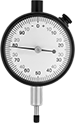
Combination Dial Plunger-Style Variance Indicators
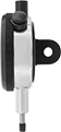
Side View
Take direct and comparative measurements with the same indicator. The combination dial has both a continuous scale numbered clockwise around the face and a balanced scale with positive values on one side of the zero and negative values on the other side. A spring-loaded plunger retracts and extends to measure objects. Rotate the dial face for viewing at multiple angles. These indicators come with a calibration certificate traceable to NIST that states they’ve passed a test for accuracy.
Remove the spindle cap and install a lifting lever (sold separately) for easier lifting of the indicator spindle.
Variance Indicators | ||||||||||||||||
|---|---|---|---|---|---|---|---|---|---|---|---|---|---|---|---|---|
Dial | Contact Point | Replacement Flat Backs | Replacement Lug Backs | |||||||||||||
| Measuring Range | Measuring Increments | Accuracy | Industry Designation | Mount. Stem Dia. | Mount. Lug Hole Dia. | Dia. | Reading | Head Dia. | Lg. | Mount. Thread Size | Each | Each | Each | |||
| 0-0.250" | 0.001" | ±0.001" | AGD Group 2 | 3/8" | 1/4" | 2 1/4" | 0-100/0-50-0 | 3/16" | 1/4" | 4-48 | 0000000 | 0000000 | 000000000 | 00000 | 000000000 | 00000 |
| 0-0.500" | 0.001" | ±0.001" | AGD Group 2 | 3/8" | 1/4" | 2 1/4" | 0-100/0-50-0 | 3/16" | 1/4" | 4-48 | 0000000 | 000000 | 000000000 | 0000 | 000000000 | 0000 |
| 0-1.000" | 0.001" | ±0.001" | AGD Group 2 | 3/8" | 1/4" | 2 1/4" | 0-100/0-50-0 | 3/16" | 1/4" | 4-48 | 0000000 | 000000 | 000000000 | 0000 | 000000000 | 0000 |
| 0-25.000mm | 0.01mm | ±0.01mm | AGD Group 2 | 3/8" | 1/4" | 2 1/4" | 0-100/0-50-0 | 3/16" | 1/4" | 4-48 | 0000000 | 000000 | 000000000 | 0000 | 000000000 | 0000 |
| Lifting Levers | 000000000 | Each | 000000 |