Connection Location Connection Location |
---|
![]() | ![]() | ![]() |
Bottom | Center Back | Lower Back |
For Use With For Use With | Show |
---|
|
For Use With For Use With | Hide |
---|
Dial Type Dial Type |
---|
![]() | ![]() |
Dry | Liquid Filled |
Display Type Display Type |
---|
|
|
System of Measurement System of Measurement |
---|
|
Measures Measures |
---|
|
Case Material Case Material |
---|
|
Connection Material Connection Material |
---|
|
Accuracy Scale Accuracy Scale |
---|
|
Connection Style Connection Style |
---|
![]() |
Threaded |
![]() |
Yor-Lok |
![]() |
Barbed |
![]() |
Compression |
Liquid Type Liquid Type |
---|
|
Accuracy Grade Accuracy Grade |
---|
|
|
Maximum Process Temperature Maximum ProcessTemperature |
---|
|
|
RoHS (Restriction of Hazardous Substances) RoHS (Restriction ofHazardous Substances) |
---|
|
REACH (Registration, Evaluation, Authorization and Restriction of Chemicals) REACH (Registration,Evaluation, Authorization and Restriction of Chemicals) |
---|
|
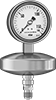
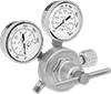
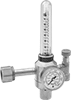
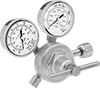
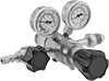
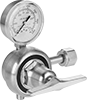
About Pressure Gauges
More
About Pipe Size
More
About Gas Regulators
More
Pressure Gauges


These are the most commonly used pressure gauges. Use them with pumps, filters, regulators, and in process lines to measure and display pressure.
Gauges with 304 stainless steel case or ABS plastic case have better corrosion resistance than gauges with brass or steel case.
For technical drawings and 3-D models, click on a part number.
- For Use With: Air, Water, Hydraulic Fluid, Carbon Dioxide, and Natural Gas
- Accuracy: ±2% Mid Scale (Grade B)
- Mount with the dial face upright
Available Pressure Ranges | |||||
---|---|---|---|---|---|
Pressure Range | Graduation Marks | Numeric Increments | |||
psi | kPa | psi | kPa | psi | kPa |
0 to 30 | 0 to 200 | 1 | 5 | 5 | 50 |
0 to 60 | 0 to 400 | 2 | 10 | 10 | 100 |
0 to 100 | 0 to 700 | 2 | 20 | 20 | 100 |
0 to 160 | 0 to 1,100 | 5 | 20 | 20 | 200 |
0 to 200 | 0 to 1,400 | 5 | 50 | 40 | 200 |
0 to 300 | 0 to 2,000 | 10 | 50 | 50 | 500 |
0 to 600 | 0 to 4,000 | 20 | 100 | 100 | 1,000 |
0 to 1,000 | 0 to 7,000 | 20 | 200 | 200 | 1,000 |
Bottom Connection | Center Back Connection | ||||||||
---|---|---|---|---|---|---|---|---|---|
Dial Diameter | Pipe Size | Environment Temp. Range, °F | Process Temp. Range, °F | Case Color | Mounting Orientation | Each | Each | ||
BSPT Male | |||||||||
1 5/8" | 1/8 | -40° to 120° | -40° to 120° | Black | Upright | 0000000 | 000000 | 0000000 | 000000 |
2" | 1/4 | -40° to 120° | -40° to 120° | Black | Upright | 0000000 | 00000 | 0000000 | 00000 |
2 1/2" | 1/4 | -40° to 120° | -40° to 120° | Black | Upright | 0000000 | 00000 | 0000000 | 00000 |
Square Panel-Mount Pressure Gauges


These gauges fit into square cutouts in your instrument panel. Use them with pumps, filters, regulators, and in process lines to measure and display pressure.
For technical drawings and 3-D models, click on a part number.
- For Use With: Air, Water, Hydraulic Fluid, Carbon Dioxide, and Natural Gas
- Accuracy: ±2.5% Full Scale (Not Graded)
Available Pressure Ranges | ||
---|---|---|
Pressure Range, psi | Graduation Marks, psi | Numeric Increments, psi |
0 to 15 | 0.5 | 1 |
0 to 30 | 1 | 5 |
0 to 60 | 2 | 10 |
0 to 100 | 1 | 10 |
0 to 160 | 5 | 20 |
0 to 200 | 2 | 20 |
0 to 300 | 10 | 50 |
Center Back Connection (Panel Mount) | ||||||||
---|---|---|---|---|---|---|---|---|
Dial | For Panel Cutout | |||||||
Ht. | Wd. | Environment Temp. Range, °F | Process Temp. Range, °F | Case Color | Ht. | Wd. | Each | |
1/8 NPT Male/10-32 UNF Female | ||||||||
2" | 2" | 0° to 140° | 0° to 140° | Black | 1 49/64" | 1 49/64" | 0000000 | 000000 |
High-Accuracy Low-Pressure Gauges


Measure small pressure changes in ventilation systems, hydraulic applications, and other critical processes with these high-accuracy gauges. Mount them with the dial face upright.
Gauges with 304 stainless steel case or polyester plastic case have better corrosion resistance than gauges with steel case.
For technical drawings and 3-D models, click on a part number.
- For Use With: Air, Water, Hydraulic Fluid, Carbon Dioxide, and Natural Gas
- Accuracy: ±1.5% Full Scale (Not Graded)
Available Pressure Gauges | ||
---|---|---|
Pressure Range, psi | Graduation Marks, psi | Numeric Increments, psi |
0 to 3 | 0.05 | 0.5 |
0 to 5 | 0.1 | 1 |
0 to 10 | 0.2 | 2 |
Bottom Connection | Center Back Connection | ||||||||
---|---|---|---|---|---|---|---|---|---|
Dial Diameter | Pipe Size | Environment Temp. Range, °F | Process Temp. Range, °F | Case Color | Mounting Orientation | Each | Each | ||
NPT Male | |||||||||
2 1/2" | 1/4 | 0° to 140° | 0° to 140° | Black | Upright | 0000000 | 000000 | 0000000 | 000000 |
NPT Male with Calibration Certificate Traceable to NIST | |||||||||
2 1/2" | 1/4 | 0° to 140° | 0° to 140° | Black | Upright | 0000000 | 000000 | 0000000 | 000000 |
- For Use With: Air, Water, Hydraulic Fluid, Carbon Dioxide, and Natural Gas
- Accuracy: ±1.5% Full Scale (Not Graded)
Available Pressure Gauges | ||
---|---|---|
Pressure Range, in. of H₂O | Graduation Marks, in. of H₂O | Numeric Increments, in. of H₂O |
0 to 10 | 0.2 | 2 |
0 to 15 | 0.2 | 3 |
0 to 30 | 0.5 | 5 |
0 to 60 | 1 | 10 |
0 to 100 | 2 | 20 |
0 to 160 | 4 | 40 |
0 to 200 | 4 | 40 |
Bottom Connection | Center Back Connection | ||||||||
---|---|---|---|---|---|---|---|---|---|
Dial Diameter | Pipe Size | Environment Temp. Range, °F | Process Temp. Range, °F | Case Color | Mounting Orientation | Each | Each | ||
NPT Male | |||||||||
2 1/2" | 1/4 | 0° to 140° | 0° to 140° | Black | Upright | 0000000 | 000000 | 0000000 | 000000 |
NPT Male with Calibration Certificate Traceable to NIST | |||||||||
2 1/2" | 1/4 | 0° to 140° | 0° to 140° | Black | Upright | 0000000 | 000000 | 0000000 | 000000 |
- For Use With: Air, Water, Hydraulic Fluid, Carbon Dioxide, and Natural Gas
- Accuracy: ±1.5% Full Scale (Not Graded)
Available Pressure Gauges | ||
---|---|---|
Pressure Range, oz./in.2 | Graduation Marks, oz./in.2 | Numeric Increments, oz./in.2 |
0 to 10 | 0.2 | 2 |
0 to 15 | 0.2 | 3 |
0 to 30 | 0.5 | 5 |
0 to 60 | 1 | 10 |
0 to 100 | 2 | 20 |
0 to 160 | 4 | 40 |
Bottom Connection | Center Back Connection | ||||||||
---|---|---|---|---|---|---|---|---|---|
Dial Diameter | Pipe Size | Environment Temp. Range, °F | Process Temp. Range, °F | Case Color | Mounting Orientation | Each | Each | ||
NPT Male | |||||||||
2 1/2" | 1/4 | 0° to 140° | 0° to 140° | Black | Upright | 0000000 | 000000 | 0000000 | 000000 |
NPT Male with Calibration Certificate Traceable to NIST | |||||||||
2 1/2" | 1/4 | 0° to 140° | 0° to 140° | Black | Upright | 0000000 | 000000 | 0000000 | 000000 |
- For Use With: Air, Water, Hydraulic Fluid, Carbon Dioxide, and Natural Gas
- Accuracy: ±1% Full Scale (Grade 1A)
Available Pressure Gauges | ||
---|---|---|
Pressure Range, psi | Graduation Marks, psi | Numeric Increments, psi |
0 to 3 | 0.05 | 0.5 |
0 to 5 | 0.1 | 1 |
0 to 10 | 0.2 | 2 |
Bottom Connection | ||||||
---|---|---|---|---|---|---|
Dial Diameter | Pipe Size | Environment Temp. Range, °F | Process Temp. Range, °F | Mounting Orientation | Each | |
NPT Male | ||||||
4" | 1/4 | 0° to 140° | 0° to 140° | Upright | 000000 | 0000000 |
- For Use With: Air, Water, Hydraulic Fluid, Carbon Dioxide, and Natural Gas
- Accuracy: ±1% Full Scale (Grade 1A)
Available Pressure Gauges | ||
---|---|---|
Pressure Range, in. of H₂O | Graduation Marks, in. of H₂O | Numeric Increments, in. of H₂O |
0 to 10 | 0.2 | 2 |
0 to 15 | 0.2 | 3 |
0 to 30 | 0.5 | 5 |
0 to 60 | 1 | 10 |
0 to 100 | 2 | 20 |
0 to 160 | 2 | 20 |
0 to 200 | 4 | 40 |
Bottom Connection | ||||||
---|---|---|---|---|---|---|
Dial Diameter | Pipe Size | Environment Temp. Range, °F | Process Temp. Range, °F | Mounting Orientation | Each | |
NPT Male | ||||||
4" | 1/4 | 0° to 140° | 0° to 140° | Upright | 000000 | 0000000 |
- For Use With: Air, Water, Hydraulic Fluid, Carbon Dioxide, and Natural Gas
- Accuracy: ±1% Full Scale (Grade 1A)
Available Pressure Gauges | ||
---|---|---|
Pressure Range, oz./in.2 | Graduation Marks, oz./in.2 | Numeric Increments, oz./in.2 |
0 to 10 | 0.2 | 2 |
0 to 15 | 0.2 | 3 |
0 to 30 | 0.5 | 5 |
0 to 60 | 1 | 10 |
Bottom Connection | ||||||
---|---|---|---|---|---|---|
Dial Diameter | Pipe Size | Environment Temp. Range, °F | Process Temp. Range, °F | Mounting Orientation | Each | |
NPT Male | ||||||
4" | 1/4 | 0° to 140° | 0° to 140° | Upright | 000000 | 0000000 |
Digital High-Accuracy Pressure Gauges


A four-digit LCD display allows for easy reading of measurements. The LCD shuts off automatically to extend battery life. Gauges are commonly used with pneumatic regulators, compressors, and in critical processes that require high accuracy, such as hydraulic and laboratory applications.
For technical drawings and 3-D models, click on a part number.
- For Use With: Air, Carbon Dioxide, Hydrogen, Nitrogen, Natural Gas
- Accuracy: ±1% Full Scale (Grade 1A)
Available Pressure Ranges | ||||
---|---|---|---|---|
Pressure Range | ||||
psi | bar | kg/cm2 | MPa | Resolution, psi |
0 to 145 | 0 to 10 | 0 to 10 | 0 to 1 | 0.1 |
Center Back Connection | ||||||||
---|---|---|---|---|---|---|---|---|
Dial Diameter | Pipe Size | Environment Temp. Range, °F | Process Temp. Range, °F | Batteries Included | Mounting Orientation | Features | Each | |
NPT Male | ||||||||
1 3/4" | 1/8 | -10° to 140° | -10° to 140° | Yes | Any | 5-min. Automatic Shut-Off | 000000 | 000000 |
1 3/4" | 1/4 | -10° to 140° | -10° to 140° | Yes | Any | 5-min. Automatic Shut-Off | 000000 | 00000 |
NPT Male with NIST Certificate | ||||||||
1 3/4" | 1/8 | -10° to 140° | -10° to 140° | Yes | Any | 5-min. Automatic Shut-Off | 00000000 | 000000 |
1 3/4" | 1/4 | -10° to 140° | -10° to 140° | Yes | Any | 5-min. Automatic Shut-Off | 00000000 | 000000 |
Vibration-Resistant Pressure Gauges


A liquid-filled dial reduces needle flutter for precise readings in high-vibration applications. Gauges are commonly used with pumps, filters, regulators, and in process lines to measure and display pressure. Mount them with the dial face upright.
Gauges with 304 stainless steel case and ABS plastic case have better corrosion resistance than gauges with brass case.
For technical drawings and 3-D models, click on a part number.
- For Use With: Air, Water, Hydraulic Fluid, Carbon Dioxide, and Natural Gas
- Accuracy: ±2.5% Full Scale (Not Graded)
Available Pressure Ranges | ||
---|---|---|
Pressure Range, psi | Graduation Marks, psi | Numeric Increments, psi |
0 to 30 | 0.5 | 5 |
0 to 60 | 1 | 10 |
0 to 100 | 2 | 20 |
0 to 160 | 4 | 40 |
0 to 300 | 5 | 50 |
0 to 2,000 | 40 | 400 |
0 to 3,000 | 50 | 500 |
0 to 5,000 | 100 | 1,000 |
Center Back Connection | ||||||||
---|---|---|---|---|---|---|---|---|
Dial Diameter | Pipe Size | Environment Temp. Range, °F | Process Temp. Range, °F | Case Color | Liquid Type | Mounting Orientation | Each | |
NPT Male | ||||||||
1 1/2" | 1/8 | 0° to 140° | 0° to 140° | Black | Glycerin | Upright | 00000000 | 000000 |
- For Use With: Air, Water, Hydraulic Fluid, Carbon Dioxide, and Natural Gas
- Accuracy: ±1% Mid Scale (Grade A)
Available Pressure Ranges | |||||
---|---|---|---|---|---|
Pressure Range | Graduation Marks | Numeric Increments | |||
psi | kPa | psi | kPa | psi | kPa |
0 to 30 | 0 to 205 | 0.5 | 5 | 5 | 50 |
0 to 60 | 0 to 410 | 1 | 10 | 10 | 100 |
0 to 100 | 0 to 680 | 2 | 20 | 20 | 200 |
0 to 160 | 0 to 1,100 | 4 | 40 | 40 | 400 |
0 to 200 | 0 to 1,360 | 4 | 40 | 40 | 400 |
0 to 300 | 0 to 2,050 | 5 | 50 | 50 | 500 |
0 to 400 | 0 to 2,700 | 10 | 100 | 100 | 1,000 |
0 to 600 | 0 to 4,100 | 10 | 100 | 100 | 1,000 |
0 to 1,000 | 0 to 6,800 | 20 | 200 | 200 | 2,000 |
0 to 1,500 | 0 to 10,200 | 20 | 200 | 300 | 3,000 |
0 to 2,000 | 0 to 13,600 | 40 | 400 | 400 | 4,000 |
0 to 3,000 | 0 to 20,500 | 50 | 500 | 500 | 5,000 |
0 to 5,000 | 0 to 34,000 | 100 | 1,000 | 1,000 | 10,000 |
0 to 6,000 | 0 to 41,000 | 100 | 1,000 | 1,000 | 10,000 |
Dial Diameter | Pipe Size | Environment Temp. Range, °F | Process Temp. Range, °F | Case Color | Liquid Type | Mounting Orientation | Each | |
NPT Male | ||||||||
---|---|---|---|---|---|---|---|---|
2 1/2" | 1/4 | 0° to 140° | 0° to 140° | Black | Glycerin | Upright | 000000 | 000000 |
Dial Diameter | Pipe Size | Environment Temp. Range, °F | Process Temp. Range, °F | Case Color | Liquid Type | Mounting Orientation | Each | |
NPT Male | ||||||||
---|---|---|---|---|---|---|---|---|
2 1/2" | 1/4 | 0° to 140° | 0° to 140° | Black | Glycerin | Upright | 000000 | 000000 |
Dial Diameter | Pipe Size | Environment Temp. Range, °F | Process Temp. Range, °F | Case Color | Liquid Type | Mounting Orientation | For Panel Cutout Dia. | Each | |
NPT Male | |||||||||
---|---|---|---|---|---|---|---|---|---|
2 1/2" | 1/4 | 0° to 140° | 0° to 140° | Black | Glycerin | Upright | 2 1/2" | 000000 | 000000 |
- For Use With: Air, Water, Hydraulic Fluid, and Natural Gas; except
With NIST Certificate: Air, Water, Hydraulic Fluid, Carbon Dioxide, Ethanol, and Natural Gas - Accuracy: ±1.5% Full Scale (Not Graded); except
2 1/2" Dia. NPT Male: ±1.% Mid Scale (Grade A)
4" Dia. NPT Male and NPT Male with NIST Certificate: ±1% Full Scale (Grade 1A)
Available Pressure Ranges | ||
---|---|---|
Gauges with NIST Certificate | ||
Pressure Range, psi | Graduation Marks, psi | Numeric Increments, psi |
NPT Male | ||
2 1/2" Dial Diameter | ||
0 to 30 | 0.5 | 5 |
0 to 60 | 1 | 10 |
0 to 100 | 2 | 20 |
0 to 160 | 4 | 40 |
0 to 200 | 4 | 40 |
0 to 300 | 5 | 50 |
0 to 400 | 10 | 100 |
0 to 600 | 10 | 100 |
0 to 800 | 20 | 200 |
0 to 1,000 | 20 | 200 |
0 to 1,500 | 20 | 300 |
0 to 2,000 | 40 | 400 |
0 to 3,000 | 50 | 500 |
0 to 5,000 | 100 | 1,000 |
0 to 6,000 | 100 | 1,000 |
0 to 10,000 | 200 | 2,000 |
4" Dial Diameter | ||
0 to 30 | 0.5 | 5 |
0 to 60 | 1 | 10 |
0 to 100 | 2 | 20 |
0 to 160 | 2 | 20 |
0 to 200 | 4 | 40 |
0 to 300 | 5 | 50 |
0 to 400 | 5 | 50 |
0 to 600 | 10 | 100 |
0 to 800 | 10 | 100 |
0 to 1,000 | 20 | 200 |
0 to 1,500 | 20 | 300 |
0 to 2,000 | 40 | 400 |
0 to 3,000 | 50 | 500 |
0 to 5,000 | 100 | 1,000 |
0 to 6,000 | 100 | 1,000 |
0 to 10,000 | 200 | 2,000 |
Dial Diameter | Pipe Size | Environment Temp. Range, °F | Process Temp. Range, °F | Liquid Type | Mounting Orientation | Each | |
Bottom Connection | |||||||
---|---|---|---|---|---|---|---|
NPT Male with NIST Certificate | |||||||
2 1/2" | 1/4 | 0° to 140° | 0° to 140° | Glycerin | Upright | 0000000 | 0000000 |
4" | 1/4 | 0° to 140° | 0° to 140° | Glycerin | Upright | 0000000 | 000000 |
Center Back Connection | |||||||
NPT Male with NIST Certificate | |||||||
2 1/2" | 1/4 | 0° to 140° | 0° to 140° | Glycerin | Upright | 0000000 | 000000 |
Lower Back Connection | |||||||
NPT Male with NIST Certificate | |||||||
4" | 1/4 | 0° to 140° | 0° to 140° | Glycerin | Upright | 0000000 | 000000 |
- For Use With: Air, Water, Hydraulic Fluid, Carbon Dioxide, and Natural Gas
- Accuracy: ±1.5% Full Scale (Not Graded)
Available Pressure Ranges | |||||
---|---|---|---|---|---|
Pressure Range | Graduation Marks | Numeric Increments | |||
psi | bar | psi | bar | psi | bar |
NPT Male | |||||
0 to 15 | 0 to 1 | 0.2 | 0.02 | 3 | 0.3 |
0 to 30 | 0 to 2 | 0.5 | 0.05 | 5 | 0.5 |
0 to 60 | 0 to 4.1 | 1 | 0.1 | 10 | 1 |
0 to 100 | 0 to 6.8 | 2 | 0.2 | 20 | 2 |
0 to 160 | 0 to 11 | 4 | 0.4 | 40 | 4 |
0 to 200 | 0 to 13.6 | 4 | 0.4 | 40 | 4 |
0 to 300 | 0 to 20.5 | 5 | 0.5 | 50 | 5 |
0 to 400 | 0 to 27 | 10 | 1 | 100 | 10 |
0 to 600 | 0 to 41 | 10 | 1 | 100 | 10 |
0 to 1,000 | 0 to 68 | 20 | 2 | 200 | 20 |
0 to 1,500 | 0 to 100 | 20 | 2 | 300 | 30 |
0 to 2,000 | 0 to 136 | 40 | 4 | 400 | 40 |
0 to 3,000 | 0 to 205 | 50 | 5 | 500 | 50 |
0 to 5,000 | 0 to 340 | 100 | 10 | 1,000 | 100 |
0 to 6,000 | 0 to 410 | 100 | 10 | 1,000 | 100 |
0 to 10,000 | 0 to 680 | 200 | 20 | 2,000 | 200 |
BSPP Male | |||||
0 to 14.4 | 0 to 1 | 0.4 | 0.02 | 4 | 0.2 |
0 to 22.8 | 0 to 1.6 | 0.6 | 0.04 | 6 | 0.4 |
0 to 36 | 0 to 2.5 | 1 | 0.05 | 10 | 0.5 |
0 to 57.6 | 0 to 4 | 1.6 | 0.1 | 16 | 1 |
0 to 86 | 0 to 6 | 2 | 0.1 | 20 | 1 |
0 to 144 | 0 to 10 | 4 | 0.2 | 40 | 2 |
0 to 228 | 0 to 16 | 6 | 0.4 | 60 | 4 |
0 to 360 | 0 to 25 | 10 | 0.5 | 100 | 5 |
0 to 576 | 0 to 40 | 16 | 1 | 160 | 10 |
0 to 860 | 0 to 60 | 20 | 1 | 200 | 10 |
0 to 1,440 | 0 to 100 | 40 | 2 | 400 | 20 |
0 to 2,280 | 0 to 160 | 60 | 4 | 600 | 40 |
0 to 3,600 | 0 to 250 | 100 | 5 | 1,000 | 50 |
0 to 5,800 | 0 to 400 | 160 | 10 | 1,600 | 100 |
0 to 8,600 | 0 to 600 | 200 | 10 | 2,000 | 100 |
Maximum-Indicating Vibration-Resistant Pressure Gauges


These gauges have a red needle that indicates the highest pressure reached since the last setting. They have a glycerin-filled dial that reduces needle flutter for precise readings in high-vibration applications. Use them with pumps, filters, regulators, and in process lines to measure and display pressure. Mount gauges with the dial face upright.
For technical drawings and 3-D models, click on a part number.
- For Use With: Air, Water, Hydraulic Fluid, Carbon Dioxide, Ethanol, and Natural Gas
- Accuracy: ±1.5% Full Scale (Not Graded)
Available Pressure Ranges | ||
---|---|---|
Pressure Range, psi | Graduation Marks, psi | Numeric Increments, psi |
0 to 15 | 0.2 | 3 |
0 to 30 | 0.5 | 5 |
0 to 60 | 1 | 10 |
0 to 100 | 2 | 20 |
0 to 160 | 4 | 40 |
0 to 200 | 4 | 40 |
0 to 300 | 5 | 50 |
0 to 400 | 10 | 100 |
0 to 600 | 10 | 100 |
0 to 1,000 | 20 | 200 |
0 to 1,500 | 20 | 300 |
0 to 3,000 | 50 | 500 |
0 to 5,000 | 100 | 1,000 |
0 to 7,500 | 100 | 1,500 |
0 to 10,000 | 200 | 2,000 |
0 to 15,000 | 200 | 3,000 |
Dial Diameter | Pipe Size | Environment Temp. Range, °F | Process Temp. Range, °F | Liquid Type | Mounting Orientation | Each | |
NPT Male | |||||||
---|---|---|---|---|---|---|---|
2 1/2" | 1/4 | 0° to 140° | 0° to 140° | Glycerin | Upright | 0000000 | 0000000 |
NPT Male with Calibration Certificate Traceable to NIST | |||||||
2 1/2" | 1/4 | 0° to 140° | 0° to 140° | Glycerin | Upright | 0000000 | 000000 |
Dial Diameter | Pipe Size | Environment Temp. Range, °F | Process Temp. Range, °F | Liquid Type | Mounting Orientation | For Panel Cutout Dia. | Each | |
NPT Male | ||||||||
---|---|---|---|---|---|---|---|---|
2 1/2" | 1/4 | 0° to 140° | 0° to 140° | Glycerin | Upright | 2 1/2" | 0000000 | 0000000 |
NPT Male with Calibration Certificate Traceable to NIST | ||||||||
2 1/2" | 1/4 | 0° to 140° | 0° to 140° | Glycerin | Upright | 2 1/2" | 0000000 | 000000 |
Vibration- and Corrosion-Resistant Pressure Gauges

Bottom Connection
And Yor-Lok Fitting

Back Connection
And Yor-Lok Fitting


Gauges with Yor-Lok connection allow for quick connections to metal tubing.
For technical drawings and 3-D models, click on a part number.
- For Use With: Air, Water, Hydraulic Fluid, Carbon Dioxide, Ethyl Alcohol, and Natural Gas
- Accuracy: ±1.5% Full Scale (Not Graded)
Available Pressure Ranges | |||||
---|---|---|---|---|---|
Pressure Range | Graduation Marks | Numeric Increments | |||
psi | kPa | psi | kPa | psi | kPa |
0 to 30 | 0 to 200 | 0.5 | 5 | 5 | 50 |
0 to 60 | 0 to 400 | 1 | 10 | 10 | 100 |
0 to 100 | 0 to 700 | 2 | 10 | 20 | 100 |
0 to 160 | 0 to 1,100 | 2 | 20 | 20 | 200 |
0 to 300 | 0 to 2,000 | 5 | 50 | 50 | 500 |
0 to 1,000 | 0 to 7,000 | 20 | 100 | 200 | 1,000 |
Dial Diameter | Environment Temp. Range, °F | Process Temp. Range, °F | For Tube OD | Mounting Orientation | Liquid Type | Compatible Tube Fittings | Each | |
Bottom Connection | ||||||||
---|---|---|---|---|---|---|---|---|
Yor-Lok Female | ||||||||
2 1/2" | 15° to 150° | 15° to 150° | 1/4" | Any | Glycerin | Parker A-Lok, Swagelok® | 0000000 | 0000000 |
Center Back Connection | ||||||||
Yor-Lok Female | ||||||||
2 1/2" | 15° to 150° | 15° to 150° | 1/4" | Any | Glycerin | Parker A-Lok, Swagelok® | 0000000 | 000000 |
Gas Pressure Gauges


Use these gauges with pumps, filters, regulators, and in process lines to monitor the pressure of compressed gas. Mount them with the dial face upright. Gauges for use with acetylene can also be used in welding applications.
Gauges with brass case are cleaned to meet ASME B40.1, Level IV for oxygen service.
For technical drawings and 3-D models, click on a part number.
- For Use With: Air, Acetylene, Carbon Dioxide, and Oxygen
- Accuracy: ±2% Mid Scale (Grade B)
Available Pressure Ranges | ||
---|---|---|
Pressure Range, psi | Graduation Marks, psi | Numeric Increments, psi |
0 to 30 | 1 | 5 |
0 to 60 | 1 | 10 |
0 to 100 | 2 | 20 |
0 to 200 | 5 | 40 |
0 to 400 | 10 | 50 |
0 to 600 | 10 | 100 |
0 to 1,000 | 20 | 200 |
0 to 2,000 | 50 | 400 |
0 to 3,000 | 50 | 500 |
0 to 4,000 | 100 | 500 |
Low-Pressure Gauges for Chemicals


A plastic or stainless steel guard, also known as an isolator, protects the gauge from damage caused by corrosive chemicals. Use them with pumps, filters, regulators, and in process lines to measure and display pressures.
Polypropylene and 316 stainless steel guards are more chemical resistant than PVC and CPVC guards.
For technical drawings and 3-D models, click on a part number.
- For Use With: Water, Salt Water, Hydraulic Fluid, Bleach, Boric Acid, and Carbon Dioxide
- Accuracy: ±2% Mid Scale (Grade B)
Available Pressure Ranges | |||||
---|---|---|---|---|---|
Pressure Range | Graduation Marks | Numeric Increments | |||
psi | kg/cm2 | psi | kg/cm2 | psi | kg/cm2 |
0 to 30 | 0 to 2.1 | 0.5 | 0.05 | 5 | 0.5 |
0 to 60 | 0 to 4.2 | 1 | 0.1 | 10 | 1 |
0 to 150 | 0 to 11.2 | 2 | 0.2 | 20 | 2 |
- For Use With: Water, Salt Water, Hydraulic Fluid, Boric Acid, and Carbon Dioxide
- Accuracy: ±2% Mid Scale (Grade B)
Available Pressure Ranges | |||||
---|---|---|---|---|---|
Pressure Range | Graduation Marks | Numeric Increments | |||
psi | kg/cm2 | psi | kg/cm2 | psi | kg/cm2 |
0 to 30 | 0 to 2.1 | 0.5 | 0.05 | 5 | 0.5 |
0 to 60 | 0 to 4.2 | 1 | 0.1 | 10 | 1 |
0 to 150 | 0 to 11.2 | 2 | 0.2 | 20 | 2 |
Bottom Connection | ||||||||
---|---|---|---|---|---|---|---|---|
Dial Diameter | Pipe Size | Environment Temp. Range, °F | Process Temp. Range, °F | Case Color | Guard Material | Guard Color | Each | |
NPT Female | ||||||||
2" | 1/4 | 40° to 240° | 40° to 240° | Black | Polypropylene Plastic | White | 0000000 | 0000000 |
Low-Pressure Differential Gauges with U-Tube
Also known as manometers, these gauges come with indicating liquid that moves up and down two columns—the difference in height between them is your pressure. They are commonly used to indicate clogged filters.
Magnet-mount gauges can be moved for use in multiple locations. Gauges with barbed tube connection have a flexible body that rolls up for storage or transport.

- For Use With: Acetylene, Air, Argon, Carbon Dioxide, and Steam
- Accuracy: Not Rated (Not Graded)
Environment Temp. Range | Process Temp. Range | Mounting | ||||||||||||||
---|---|---|---|---|---|---|---|---|---|---|---|---|---|---|---|---|
Pressure Range, in. of H₂O | Scale Range, in. of H₂O | Numeric Increments, in. of H₂O | Graduation Marks, in. of H₂O | Max. Pressure, psi | Ht. | Min., °F | Max., °F | Min., °F | Max., °F | Gender | Mount Type | Fasteners Included | Hole Dia. | Number of Holes | Each | |
With 1/4 NPT Female Threaded Pipe Connection | ||||||||||||||||
0-10 | 5-0-5 | 1 | 0.1 | 250 | 14" | 35° | 150° | 35° | 250° | Female | Screw On | No | 3/16" | 4 | 0000000 | 0000000 |
0-15 | 7-0-7 | 1 | 0.1 | 250 | 18" | 35° | 150° | 35° | 250° | Female | Screw On | No | 3/16" | 4 | 0000000 | 000000 |

- For Use With: Air, Argon, Carbon Dioxide, and Hydrogen
- Accuracy: Not Rated (Not Graded)
Pressure Range, in. of H₂O | Scale Range, in. of H₂O | Numeric Increments, in. of H₂O | Graduation Marks, in. of H₂O | Max. Pressure | Ht. | Max. Process Temp., °F | Gender | Mount Type | Each | |
With Barbed Tube Connection for 3/16" Tube ID | ||||||||||
---|---|---|---|---|---|---|---|---|---|---|
0-8 | 4-0-4 | 1 | 0.1 | Not Rated | 17" | 130° | Male | Magnet | 0000000 | 0000000 |
0-12 | 6-0-6 | 1 | 0.1 | Not Rated | 21" | 130° | Male | Magnet | 0000000 | 000000 |
0-16 | 8-0-8 | 1 | 0.1 | Not Rated | 25" | 130° | Male | Magnet | 0000000 | 000000 |
0-24 | 12-0-12 | 1 | 0.1 | Not Rated | 33" | 130° | Male | Magnet | 0000000 | 000000 |
0-30 | 15-0-15 | 1 | 0.1 | Not Rated | 39" | 130° | Male | Magnet | 0000000 | 000000 |
0-36 | 18-0-18 | 1 | 0.1 | Not Rated | 45" | 130° | Male | Magnet | 0000000 | 000000 |
0-48 | 24-0-24 | 1 | 0.1 | Not Rated | 57" | 130° | Male | Magnet | 0000000 | 000000 |
0-60 | 30-0-30 | 1 | 0.1 | Not Rated | 69" | 130° | Male | Magnet | 0000000 | 000000 |
0-72 | 36-0-36 | 1 | 0.1 | Not Rated | 81" | 130° | Male | Magnet | 0000000 | 000000 |

- For Use With: Air, Argon, Carbon Dioxide, and Hydrogen
- Accuracy: Not Rated (Not Graded)
Pressure Range, in. of H₂O | Scale Range, in. of H₂O | Numeric Increments, in. of H₂O | Graduation Marks, in. of H₂O | Max. Pressure, psi | Ht. | Gender | Mount Type | Each | |
With Compression Tube Connection for 1/4" Tube OD | |||||||||
---|---|---|---|---|---|---|---|---|---|
0-8 | 4-0-4 | 1 | 0.1 | 100 | 20" | Female | Magnet | 0000000 | 0000000 |
0-12 | 6-0-6 | 1 | 0.1 | 100 | 25" | Female | Magnet | 0000000 | 000000 |
0-16 | 8-0-8 | 1 | 0.1 | 100 | 30" | Female | Magnet | 0000000 | 000000 |
0-20 | 10-0-10 | 1 | 0.1 | 100 | 34" | Female | Magnet | 0000000 | 000000 |
0-24 | 12-0-12 | 1 | 0.1 | 100 | 39" | Female | Magnet | 0000000 | 000000 |
0-36 | 18-0-18 | 1 | 0.1 | 100 | 58" | Female | Magnet | 0000000 | 000000 |
Low-Pressure Differential Gauges with Color Indicator
A band of green, yellow, and red provides a clear indication of changes in differential pressure. Gauges are commonly used to indicate clogged filters.
For technical drawings and 3-D models, click on a part number.

- For Use With: Air, Water, Hydraulic Fluid, Carbon Dioxide, Nitrogen, Hydrogen, Argon, and Acetylene
- Accuracy: ±5% Full Scale (Not Graded)
Pressure Range, psi | ||||||||||||
---|---|---|---|---|---|---|---|---|---|---|---|---|
Pipe Size | Green Band | Yellow Band | Red Band | Max. Pressure, psi | Environment Temp. Range, °F | Process Temp. Range, °F | Ht. | Wd. | Dp. | Case Color | Each | |
NPT Female | ||||||||||||
1/4 | 0-2 | 2-2.5 | 2.5-3.5 | 300 | -40° to 200° | -40° to 200° | 3 1/4" | 3 1/4" | 1 1/2" | Black | 0000000 | 000000 |
1/4 | 0-3 | 3-4.5 | 4.5-5 | 300 | -40° to 200° | -40° to 200° | 3 1/4" | 3 1/4" | 1 1/2" | Black | 0000000 | 00000 |
1/4 | 0-6 | 6-9 | 9-12 | 300 | -40° to 200° | -40° to 200° | 3 1/4" | 3 1/4" | 1 1/2" | Black | 0000000 | 00000 |
1/4 | 0-7.5 | 7.5-12 | 12-15 | 300 | -40° to 200° | -40° to 200° | 3 1/4" | 3 1/4" | 1 1/2" | Black | 0000000 | 00000 |
1/4 | 0-13 | 13-20 | 20-30 | 300 | -40° to 200° | -40° to 200° | 3 1/4" | 3 1/4" | 1 1/2" | Black | 0000000 | 00000 |
1/4 | 0-19.5 | 19.5-29.5 | 29.5-43 | 300 | -40° to 200° | -40° to 200° | 3 1/4" | 3 1/4" | 1 1/2" | Black | 0000000 | 00000 |
Absolute Pressure Gauges


Unlike other gauges that measure the difference between your system and the atmosphere, these give measurements relative to zero pressure. They’re often used in laboratory applications, and they are barometrically independent.
Stainless steel gauges have excellent corrosion resistance, so they can be used with more corrosive liquids and gasses than gauges with a brass connection and aluminum case.
For technical drawings and 3-D models, click on a part number.
- For Use With: Air, Carbon Dioxide, Diesel Fuel, Ethyl Alcohol, Gasoline, Hydraulic Fluid, Natural Gas, Water
- Accuracy: ±1% Full Scale (Not Graded)
Available Pressure Ranges | ||
---|---|---|
Pressure Range, mbar | Numeric Increments, mbar | Graduation Marks, mbar |
0 to 25 | 5 | 0.5 |
0 to 60 | 10 | 1 |
0 to 160 | 50 | 5 |
0 to 600 | 100 | 10 |
0 to 1,000 | 200 | 20 |
Bottom Connection | ||||||
---|---|---|---|---|---|---|
Dial Diameter | Pipe Size | Environment Temp. Range, °F | Process Temp. Range, °F | Lens Material | Each | |
BSPP Male | ||||||
4" | 1/2 | 5° to 120° | 0° to 200° | Glass | 000000 | 000000000 |
Tank-Mount Pressure-Regulating Valves for Air and Inert Gas
- For Use With: See Table
- Temperature Range: -20° to 120° F
These valves automatically reduce a high inlet pressure from compressed gas tanks to a lower, stable outlet pressure. All have Compressed Gas Association (CGA) numbered inlet fittings for secure connections to compressed gas tanks. Choose a valve with the same CGA number as your tank and other system components. Valves have a gauge to monitor outlet pressure and a gauge to monitor inlet pressure from the tank.
Choose a valve with a maximum outlet pressure that’s approximately twice your application’s normal operating pressure. Your operating pressure should never exceed 75% of the valve’s maximum outlet pressure.
Single-stage valves reduce pressure in one step, which causes the outlet pressure to fluctuate slightly as you empty the tank. They’re best for applications where a constant outlet pressure isn’t critical.
Two-stage valves progressively reduce pressure over two steps for more consistent outlet pressure at all times. They’re often used in applications that require a constant outlet pressure regardless of the tank level.
Valves with a brass body have a longer service life than valves with a brass and steel body.
Valves with a stainless steel diaphragm can withstand harsh environments.


Inlet | Outlet | Material | ||||||||||
---|---|---|---|---|---|---|---|---|---|---|---|---|
CGA Number | Location | Thread Direction | Pressure Gauge Range, psi | Location | Thread Direction | Pressure Range, psi | Pressure Adjustment Method | Body | Seal | Diaphragm | Each | |
For Use With Carbon Dioxide | ||||||||||||
5/8"-18 UNF Female Outlet × NGO Female Inlet | ||||||||||||
CGA 320 | Side | Right Hand | 0 to 4,000 | Side | Right Hand | 0 to 145 | Knob | Brass | PTFE | Neoprene | 00000000 | 0000000 |
9/16"-18 UNF Male Outlet × NGO Female Inlet | ||||||||||||
CGA 320 | Side | Right Hand | 0 to 4,000 | Side | Right Hand | 0 to 125 | T-Handle | Brass | PTFE | Rubber | 0000000 | 000000 |

Inlet | Outlet | Material | ||||||||||
---|---|---|---|---|---|---|---|---|---|---|---|---|
CGA Number | Location | Thread Direction | Pressure Gauge Range, psi | Location | Thread Direction | Pressure Range, psi | Pressure Adjustment Method | Body | Seal | Diaphragm | Each | |
For Use With Carbon Dioxide | ||||||||||||
1/4 NPT Female Outlet × NGO Female Inlet | ||||||||||||
CGA 320 | Side | Right Hand | 0 to 4,000 | Side | Right Hand | 0 to 250 | T-Handle | Brass | PTFE | Neoprene | 00000000 | 0000000 |
CGA 320 | Side | Right Hand | 0 to 4,000 | Side | Right Hand | 0 to 250 | T-Handle | Brass | PTFE | Stainless Steel | 00000000 | 000000 |
5/8"-18 UNF Female Outlet × NGO Female Inlet | ||||||||||||
CGA 320 | Side | Right Hand | 0 to 4,000 | Side | Right Hand | 0 to 125 | T-Handle | Brass | PTFE | Stainless Steel | 00000000 | 000000 |
CGA 320 | Side | Right Hand | 0 to 4,000 | Side | Right Hand | 0 to 125 | T-Handle | Brass/Steel | PTFE | Rubber | 0000000 | 000000 |
Easy-Read Tank-Mount Pressure-Regulating Valves with Flowmeter for Inert Gas

- For Use With: See Table
Flowmeters let you see the gas flow rate from a distance. These valves automatically reduce a high inlet pressure from compressed gas tanks to a lower, stable outlet pressure. All have Compressed Gas Association (CGA) numbered inlet fittings for secure connections to compressed gas tanks. Choose a valve with the same CGA number as your tank and other system components. They have a gauge for monitoring inlet pressure from the tank.
Single-stage valves reduce pressure in one step, which causes the outlet pressure to fluctuate slightly as you empty the tank. They’re best for applications where a constant outlet pressure isn’t critical.
Valves with one flowmeter are for one piece of equipment on a tank. The flowmeter has a single scale.
Adapters (sold separately) change 5/8"-18 outlets to 9/16"-18 male connections, and vice versa.
Inlet | Outlet | Material | ||||||||||||
---|---|---|---|---|---|---|---|---|---|---|---|---|---|---|
CGA Number | Location | Thread Direction | Pressure Gauge Range, psi | Stage | Thread Size | Location | Thread Direction | Flow Range, scfh | Number of Flowmeters | Body | Seal | Diaphragm | Each | |
UNF Female Outlet × NGO Female Inlet | ||||||||||||||
CGA 320 | Side | Right Hand | 0 to 4,000 | Single | 5/8"-18 | Side | Right Hand | 0 to 70 | 1 | Brass | PTFE | Neoprene | 00000000 | 0000000 |
Optional Adapter | 00000000 | Each | 000000 |
Tank-Mount Pressure-Regulating Valves with Flowmeter for Inert Gas
- For Use With: See Table
- Temperature Range: -20° to 120° F
Commonly used in TIG welding where gas flow/coverage is a concern, these valves measure the gas flow rate in addition to regulating pressure. They automatically reduce a high inlet pressure from compressed gas tanks to a lower, stable outlet pressure. All have Compressed Gas Association (CGA) numbered inlet fittings for secure connections to compressed gas tanks. Choose a valve with the same CGA number as your tank and other system components. Valves have a gauge to monitor the outlet flow rate and a second gauge to monitor inlet pressure from the tank. They are single stage and reduce pressure in one step, which causes the outlet pressure to fluctuate slightly as you empty the tank.


Inlet | Outlet | Material | |||||||||||||
---|---|---|---|---|---|---|---|---|---|---|---|---|---|---|---|
CGA Number | Location | Thread Direction | Pressure Gauge Range, psi | Stage | Thread Size | Location | Thread Direction | Flow Range, scfh | Flow Gauge Included | Body | Seal | Diaphragm | Includes | Each | |
UNF Female Outlet × NGO Female Inlet | |||||||||||||||
CGA 320 | Side | Right Hand | 0 to 4,000 | Single | 5/8"-18 | Side | Right Hand | 0 to 60 | Yes | Brass | PTFE | Neoprene | __ | 0000000 | 0000000 |
CGA 320 | Side | Right Hand | 0 to 4,000 | Single | 5/8"-18 | Side | Right Hand | 0 to 60 | Yes | Brass | PTFE | Neoprene | 10-ft. long, 3/16" dia. hose with 5/8"-18 male fittings on both ends | 0000000 | 000000 |
CGA 320 | Side | Right Hand | 0 to 4,000 | Single | 5/8"-18 | Side | Right Hand | 0 to 100 | Yes | Brass | PTFE | Neoprene | __ | 0000000 | 000000 |
High-Purity Tank-Mount Pressure-Regulating Valves for Inert Gas
- For Use With: See Table
- Temperature Range: -20° to 120° F
Reduce contaminants in research sample systems, emission monitoring systems, chromatography, and other high-purity applications that use argon, helium, nitrogen, or carbon dioxide. These valves have a 316 stainless steel and brass body with a smooth finish to reduce dust collection and internal components designed to protect the seal and diaphragm from contamination. They automatically reduce a high inlet pressure from compressed gas tanks to a lower, stable outlet pressure. All have Compressed Gas Association (CGA) numbered inlet fittings for secure connections to compressed gas tanks. Choose a valve with the same CGA number as your tank and other system components. Outlet fittings are Swagelok® for a leak-free seal around hard metal tubing in high-pressure lines. Also known as instrumentation fittings, Swagelok® fittings are compatible with Parker A-Lok, Gyrolok, Bilok, and Tylok fittings. Valves have a gauge to monitor outlet pressure and a gauge to monitor inlet pressure from the tank.
Choose a valve with a maximum outlet pressure that’s approximately twice your application’s normal operating pressure. Your operating pressure should never exceed 75% of the valve’s maximum outlet pressure.
Single-stage valves reduce pressure in one step, which causes the outlet pressure to fluctuate slightly as you empty the tank. They’re best for applications where a constant outlet pressure isn’t critical.
Two-stage valves progressively reduce pressure over two steps for more consistent outlet pressure at all times. They’re often used in applications that require a constant outlet pressure regardless of the tank level.
Chrome-plated valves add a layer of corrosion resistance.


Inlet | Outlet | |||||||||
---|---|---|---|---|---|---|---|---|---|---|
CGA Number | Location | Thread Direction | Pressure Gauge Range, psi | Stage | For Tube OD | Location | Pressure Range, psi | Pressure Adjustment Method | Each | |
Swagelok® Female Outlet × NGO Female Inlet | ||||||||||
Brass Body—316 Stainless Steel Diaphragm and PTFE Seal | ||||||||||
CGA 320 | Side | Right Hand | 0 to 4,000 | Single | 1/4" | Side | 0 to 15 | Knob | 0000000 | 0000000 |
CGA 320 | Side | Right Hand | 0 to 4,000 | Single | 1/4" | Side | 0 to 125 | Knob | 0000000 | 000000 |
CGA 320 | Side | Right Hand | 0 to 4,000 | Two | 1/4" | Side | 0 to 125 | Knob | 0000000 | 000000 |
Chrome-Plated Brass Body—316 Stainless Steel Diaphragm and PTFE Seal | ||||||||||
CGA 320 | Side | Right Hand | 0 to 4,000 | Single | 1/4" | Side | 0 to 15 | Knob | 0000000 | 000000 |
CGA 320 | Side | Right Hand | 0 to 4,000 | Single | 1/4" | Side | 0 to 50 | Knob | 0000000 | 000000 |
CGA 320 | Side | Right Hand | 0 to 4,000 | Single | 1/4" | Side | 0 to 125 | Knob | 0000000 | 000000 |
CGA 320 | Side | Right Hand | 0 to 4,000 | Two | 1/4" | Side | 0 to 15 | Knob | 0000000 | 000000 |
CGA 320 | Side | Right Hand | 0 to 4,000 | Two | 1/4" | Side | 0 to 50 | Knob | 0000000 | 000000 |
CGA 320 | Side | Right Hand | 0 to 4,000 | Two | 1/4" | Side | 0 to 125 | Knob | 0000000 | 000000 |
Tank-Mount Pressure-Regulating Valves for Cryogenic Cylinders

- For Use With: See Table
- Temperature Range: -20° to 120° F
Automatically reduce a high inlet pressure from compressed gas tanks to a lower, stable outlet pressure. These valves can remove gases from liquid cryogenic cylinders. They have Compressed Gas Association (CGA) numbered inlet fittings for secure connections to compressed gas tanks. Choose a valve with the same CGA number as your tank and other system components. Valves come with a gauge to monitor outlet pressure. They are single stage and reduce pressure in one step, which causes the outlet pressure to fluctuate slightly as you empty the tank.
Choose a valve with a maximum outlet pressure that’s approximately twice your application’s normal operating pressure. Your operating pressure should never exceed 75% of the valve’s maximum outlet pressure.
Inlet | Outlet | ||||||||||
---|---|---|---|---|---|---|---|---|---|---|---|
For Use With | CGA Number | Location | Thread Direction | Stage | Thread Size | Location | Thread Direction | Pressure Range, psi | Pressure Adjustment Method | Each | |
UNF Male Outlet × NGO Female Inlet | |||||||||||
Brass Body—Stainless Steel Diaphragm and PTFE Seal | |||||||||||
Carbon Dioxide | CGA 320 | Side | Right Hand | Single | 9/16"-18 | Bottom | Right Hand | 0 to 350 | T-Handle | 0000000 | 0000000 |