For Use With For Use With | Show |
|---|
|
For Use With For Use With | Hide |
|---|
Thread Type Thread Type |
|---|
Body Material Body Material |
|---|
|

Maximum Pressure Maximum Pressure |
|---|
|
Maximum Flow Maximum Flow |
|---|
Mounting Orientation Mounting Orientation |
|---|
|
System of Measurement System of Measurement |
|---|
|
Fitting Material Fitting Material |
|---|
|
Flow Measurement Scale Flow Measurement Scale |
|---|
|
Display Type Display Type |
|---|
| Scale | |
Set Point Set Point |
|---|
DFARS (Defense Acquisition Regulations Supplement) DFARS (Defense AcquisitionRegulations Supplement) |
|---|
RoHS (Restriction of Hazardous Substances) RoHS (Restriction ofHazardous Substances) |
|---|
|
REACH (Registration, Evaluation, Authorization and Restriction of Chemicals) REACH (Registration,Evaluation, Authorization and Restriction of Chemicals) |
|---|
|
About Flowmeters and Totalizers
Flowmeters measure the rate of flow for a liquid or a gas. Totalizers measure the cumulative flow volume. Flowmeter/totalizers display both the flow rate and the cumulative flow volume.
More
About Vacuum Pumps
More
How to Identify and Measure Fittings
Pipe size is an industry designation, not the actual size. View information about how to measure threaded and unthreaded pipe and pipe fittings.
More
Flowmeters for Inert Gas
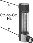
The correlated scale and conversion charts let you use the same flowmeter to measure the flow rate of nitrogen, oxygen, argon, and helium. These flowmeters have fittings on the back for installation in your instrument panel. The flow-control knob lets you open and close the valve at the inlet to adjust the flow rate within the range.
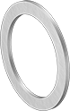
316 stainless steel fittings are more corrosion resistant than aluminum fittings.
![]() For technical drawings and 3-D models, click on a part number.
For technical drawings and 3-D models, click on a part number.
| Pipe Connections | Overall Ht. | Ctr.-to-Ctr. Ht. | Flow Range, cc/min. | Accuracy | Max. Pressure | Max. Temp., °F | Case Material | Window Material | Seal Material | Mounting Orientation | Features | Each | |
Glass Body with 316 Stainless Steel Fittings | |||||||||||||
|---|---|---|---|---|---|---|---|---|---|---|---|---|---|
Cubic Centimeters per Minute | |||||||||||||
| 1/8 NPT Female | 5 1/2" | 4 1/2" | 0 to 50 | ±10% | 200 psi @ 70° F | 200° | Aluminum | Polycarbonate Plastic | Fluoroelastomer Rubber | Vertical | Flow-Control Knob | 0000000 | 0000000 |
| 1/8 NPT Female | 5 1/2" | 4 1/2" | 0 to 103 | ±10% | 200 psi @ 70° F | 200° | Aluminum | Polycarbonate Plastic | Fluoroelastomer Rubber | Vertical | Flow-Control Knob | 0000000 | 000000 |
| 1/8 NPT Female | 5 1/2" | 4 1/2" | 0 to 400 | ±10% | 200 psi @ 70° F | 200° | Aluminum | Polycarbonate Plastic | Fluoroelastomer Rubber | Vertical | Flow-Control Knob | 0000000 | 000000 |
| 1/8 NPT Female | 5 1/2" | 4 1/2" | 0 to 900 | ±10% | 200 psi @ 70° F | 200° | Aluminum | Polycarbonate Plastic | Fluoroelastomer Rubber | Vertical | Flow-Control Knob, Water Flow Scale (0-18.2 ccm) | 0000000 | 000000 |
| 1/8 NPT Female | 5 1/2" | 4 1/2" | 0 to 2,580 | ±10% | 200 psi @ 70° F | 200° | Aluminum | Polycarbonate Plastic | Fluoroelastomer Rubber | Vertical | Flow-Control Knob, Water Flow Scale (0-55 ccm) | 0000000 | 000000 |
| 1/8 NPT Female | 5 1/2" | 4 1/2" | 0 to 3,840 | ±10% | 200 psi @ 70° F | 200° | Aluminum | Polycarbonate Plastic | Fluoroelastomer Rubber | Vertical | Flow-Control Knob, Water Flow Scale (0-90 ccm) | 0000000 | 000000 |
| 1/8 NPT Female | 5 1/2" | 4 1/2" | 0 to 6,000 | ±10% | 200 psi @ 70° F | 200° | Aluminum | Polycarbonate Plastic | Fluoroelastomer Rubber | Vertical | Flow-Control Knob, Water Flow Scale (0-130 ccm) | 0000000 | 000000 |
| 1/8 NPT Female | 5 1/2" | 4 1/2" | 0 to 10,100 | ±10% | 200 psi @ 70° F | 200° | Aluminum | Polycarbonate Plastic | Fluoroelastomer Rubber | Vertical | Flow-Control Knob, Water Flow Scale (0-235 ccm) | 0000000 | 000000 |
| 1/8 NPT Female | 5 1/2" | 4 1/2" | 0 to 15,750 | ±10% | 200 psi @ 70° F | 200° | Aluminum | Polycarbonate Plastic | Fluoroelastomer Rubber | Vertical | Flow-Control Knob, Water Flow Scale (0-375 ccm) | 0000000 | 000000 |
| 1/8 NPT Female | 5 1/2" | 4 1/2" | 0 to 23,640 | ±10% | 200 psi @ 70° F | 200° | Aluminum | Polycarbonate Plastic | Fluoroelastomer Rubber | Vertical | Flow-Control Knob, Water Flow Scale (0-570 ccm) | 0000000 | 000000 |
| 1/8 NPT Female | 10" | 8 7/8" | 0 to 50 | ±5% | 200 psi @ 70° F | 200° | Aluminum | Polycarbonate Plastic | Fluoroelastomer Rubber | Vertical | Flow-Control Knob | 0000000 | 000000 |
| 1/8 NPT Female | 10" | 8 7/8" | 0 to 103 | ±5% | 200 psi @ 70° F | 200° | Aluminum | Polycarbonate Plastic | Fluoroelastomer Rubber | Vertical | Flow-Control Knob | 00000000 | 000000 |
| 1/8 NPT Female | 10" | 8 7/8" | 0 to 400 | ±5% | 200 psi @ 70° F | 200° | Aluminum | Polycarbonate Plastic | Fluoroelastomer Rubber | Vertical | Flow-Control Knob | 00000000 | 000000 |
| 1/8 NPT Female | 10" | 8 7/8" | 0 to 855 | ±5% | 200 psi @ 70° F | 200° | Aluminum | Polycarbonate Plastic | Fluoroelastomer Rubber | Vertical | Flow-Control Knob, Water Flow Scale (0-18 ccm) | 0000000 | 000000 |
| 1/8 NPT Female | 10" | 8 7/8" | 0 to 2,290 | ±5% | 200 psi @ 70° F | 200° | Aluminum | Polycarbonate Plastic | Fluoroelastomer Rubber | Vertical | Flow-Control Knob, Water Flow Scale (0-50 ccm) | 0000000 | 000000 |
| 1/8 NPT Female | 10" | 8 7/8" | 0 to 3,425 | ±5% | 200 psi @ 70° F | 200° | Aluminum | Polycarbonate Plastic | Fluoroelastomer Rubber | Vertical | Flow-Control Knob, Water Flow Scale (0-75 ccm) | 0000000 | 000000 |
| 1/8 NPT Female | 10" | 8 7/8" | 0 to 9,180 | ±5% | 200 psi @ 70° F | 200° | Aluminum | Polycarbonate Plastic | Fluoroelastomer Rubber | Vertical | Flow-Control Knob, Water Flow Scale (0-215 ccm) | 0000000 | 000000 |
| 1/8 NPT Female | 10" | 8 7/8" | 0 to 23,740 | ±5% | 200 psi @ 70° F | 200° | Aluminum | Polycarbonate Plastic | Fluoroelastomer Rubber | Vertical | Flow-Control Knob, Water Flow Scale (0-565 ccm) | 0000000 | 000000 |
Glass Body with Aluminum Fittings | |||||||||||||
Cubic Centimeters per Minute | |||||||||||||
| 1/8 NPT Female | 5 1/2" | 4 1/2" | 0 to 50 | ±10% | 200 psi @ 70° F | 200° | Aluminum | Polycarbonate Plastic | Buna-N Rubber | Vertical | Flow-Control Knob | 0000000 | 000000 |
| 1/8 NPT Female | 5 1/2" | 4 1/2" | 0 to 103 | ±10% | 200 psi @ 70° F | 200° | Aluminum | Polycarbonate Plastic | Buna-N Rubber | Vertical | Flow-Control Knob | 0000000 | 000000 |
| 1/8 NPT Female | 5 1/2" | 4 1/2" | 0 to 400 | ±10% | 200 psi @ 70° F | 200° | Aluminum | Polycarbonate Plastic | Buna-N Rubber | Vertical | Flow-Control Knob | 0000000 | 000000 |
| 1/8 NPT Female | 5 1/2" | 4 1/2" | 0 to 900 | ±10% | 200 psi @ 70° F | 200° | Aluminum | Polycarbonate Plastic | Buna-N Rubber | Vertical | Flow-Control Knob, Water Flow Scale (0-18.2 ccm) | 0000000 | 000000 |
| 1/8 NPT Female | 5 1/2" | 4 1/2" | 0 to 2,580 | ±10% | 200 psi @ 70° F | 200° | Aluminum | Polycarbonate Plastic | Buna-N Rubber | Vertical | Flow-Control Knob, Water Flow Scale (0-55 ccm) | 0000000 | 000000 |
| 1/8 NPT Female | 5 1/2" | 4 1/2" | 0 to 3,840 | ±10% | 200 psi @ 70° F | 200° | Aluminum | Polycarbonate Plastic | Buna-N Rubber | Vertical | Flow-Control Knob, Water Flow Scale (0-90 ccm) | 0000000 | 000000 |
| 1/8 NPT Female | 5 1/2" | 4 1/2" | 0 to 6,000 | ±10% | 200 psi @ 70° F | 200° | Aluminum | Polycarbonate Plastic | Buna-N Rubber | Vertical | Flow-Control Knob, Water Flow Scale (0-130 ccm) | 0000000 | 000000 |
| 1/8 NPT Female | 5 1/2" | 4 1/2" | 0 to 10,100 | ±10% | 200 psi @ 70° F | 200° | Aluminum | Polycarbonate Plastic | Buna-N Rubber | Vertical | Flow-Control Knob, Water Flow Scale (0-235 ccm) | 0000000 | 000000 |
| 1/8 NPT Female | 5 1/2" | 4 1/2" | 0 to 15,750 | ±10% | 200 psi @ 70° F | 200° | Aluminum | Polycarbonate Plastic | Buna-N Rubber | Vertical | Flow-Control Knob, Water Flow Scale (0-375 ccm) | 0000000 | 000000 |
| 1/8 NPT Female | 5 1/2" | 4 1/2" | 0 to 23,640 | ±10% | 200 psi @ 70° F | 200° | Aluminum | Polycarbonate Plastic | Buna-N Rubber | Vertical | Flow-Control Knob, Water Flow Scale (0-570 ccm) | 0000000 | 000000 |
| 1/8 NPT Female | 10" | 8 7/8" | 0 to 50 | ±5% | 200 psi @ 70° F | 200° | Aluminum | Polycarbonate Plastic | Buna-N Rubber | Vertical | Flow-Control Knob | 0000000 | 000000 |
| 1/8 NPT Female | 10" | 8 7/8" | 0 to 103 | ±5% | 200 psi @ 70° F | 200° | Aluminum | Polycarbonate Plastic | Buna-N Rubber | Vertical | Flow-Control Knob | 00000000 | 000000 |
| 1/8 NPT Female | 10" | 8 7/8" | 0 to 400 | ±5% | 200 psi @ 70° F | 200° | Aluminum | Polycarbonate Plastic | Buna-N Rubber | Vertical | Flow-Control Knob | 00000000 | 000000 |
| 1/8 NPT Female | 10" | 8 7/8" | 0 to 855 | ±5% | 200 psi @ 70° F | 200° | Aluminum | Polycarbonate Plastic | Buna-N Rubber | Vertical | Flow-Control Knob, Water Flow Scale (0-18 ccm) | 0000000 | 000000 |
| 1/8 NPT Female | 10" | 8 7/8" | 0 to 2,290 | ±5% | 200 psi @ 70° F | 200° | Aluminum | Polycarbonate Plastic | Buna-N Rubber | Vertical | Flow-Control Knob, Water Flow Scale (0-50 ccm) | 0000000 | 000000 |
| 1/8 NPT Female | 10" | 8 7/8" | 0 to 3,425 | ±5% | 200 psi @ 70° F | 200° | Aluminum | Polycarbonate Plastic | Buna-N Rubber | Vertical | Flow-Control Knob, Water Flow Scale (0-75 ccm) | 0000000 | 000000 |
| 1/8 NPT Female | 10" | 8 7/8" | 0 to 9,180 | ±5% | 200 psi @ 70° F | 200° | Aluminum | Polycarbonate Plastic | Buna-N Rubber | Vertical | Flow-Control Knob, Water Flow Scale (0-215 ccm) | 0000000 | 000000 |
| 1/8 NPT Female | 10" | 8 7/8" | 0 to 23,740 | ±5% | 200 psi @ 70° F | 200° | Aluminum | Polycarbonate Plastic | Buna-N Rubber | Vertical | Flow-Control Knob, Water Flow Scale (0-565 ccm) | 0000000 | 000000 |
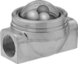
Flow Sights with Barbed Fittings for Water, Oil, Air, and Inert Gas
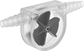
Monitor liquid movement, color, and clarity in tube systems—these sights have barbed fittings that slide into soft plastic and rubber tubing. They have a clear body and an indicator that moves when flow is present, so you can visually confirm flow from a distance.
Indicator | ||||||||||
|---|---|---|---|---|---|---|---|---|---|---|
| For Tube ID | Temp. Range, °F | End-to-End Lg. | Ht. | Max. Pressure | Direction of Flow | Material | Color | For Use With | Each | |
Ball Indicator | ||||||||||
Polycarbonate Plastic Body | ||||||||||
| 1/4" to 3/8" | 32° to 180° | 3" | 2 1/4" | 10 psi @ 70° F | Bottom to Top, Left to Right, Right to Left, Top to Bottom | Nylon Plastic | White | Water, Oil, Air, Inert Gas | 0000000 | 000000 |
Rotor Indicator | ||||||||||
Polymethylpentene Plastic Body | ||||||||||
| 1/4" to 7/16" | 32° to 140° | 3 1/2" | 1 9/16" | 20 psi @ 70° F | Bottom to Top, Left to Right, Right to Left, Top to Bottom | Polypropylene Plastic | Blue | Water, Mineral Oil, Air, Inert Gas | 0000000 | 00000 |
Polystyrene Plastic Body | ||||||||||
| 3/16" to 1/4" | 0° to 190° | 2" | 1" | 10 psi @ 70° F | Bottom to Top, Left to Right, Right to Left, Top to Bottom | Polystyrene Plastic | Blue | Water, Oil, Air, Inert Gas | 0000000 | 00000 |
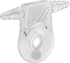
Panel-Mount Flow Sights for Water, Oil, and Inert Gas
The included mounting ring lets you install these sights in instrument panels. They have three ball indicators that bounce in the domed-top window to show flow in your line.
Flow Sights | |||||||||||||||
|---|---|---|---|---|---|---|---|---|---|---|---|---|---|---|---|
Indicator | Repair Kits | ||||||||||||||
| Pipe Size | Thread Type | Gender | Temp. Range, °F | Window Dia. | End-to-End Lg. | Ht. | Max. Pressure | Panel Cutout Dia. | Direction of Flow | No. of | Material | Each | Each | ||
Brass Body | |||||||||||||||
| 1/4 | NPT | Female | 35° to 120° | 1 5/8" | 3 1/8" | 2 1/8" | 150 psi @ 70° F | 2 3/8" | Bottom to Top, Left to Right, Right to Left, Top to Bottom | 3 | White Polyethylene Plastic White Polyethylene Plastic Green Acrylic Plastic | 0000000 | 0000000 | 00000000 | 000000 |
| 3/8 | NPT | Female | 35° to 120° | 1 5/8" | 3 1/8" | 2 1/8" | 150 psi @ 70° F | 2 3/8" | Bottom to Top, Left to Right, Right to Left, Top to Bottom | 3 | White Polyethylene Plastic White Polyethylene Plastic Green Acrylic Plastic | 0000000 | 000000 | 00000000 | 00000 |
| 1/2 | NPT | Female | 35° to 120° | 1 5/8" | 3 1/8" | 2 1/8" | 150 psi @ 70° F | 2 3/8" | Bottom to Top, Left to Right, Right to Left, Top to Bottom | 3 | White Polyethylene Plastic White Polyethylene Plastic Green Acrylic Plastic | 0000000 | 000000 | 00000000 | 00000 |
| 3/4 | NPT | Female | 35° to 120° | 1 5/8" | 3 1/8" | 2 1/8" | 150 psi @ 70° F | 2 3/8" | Bottom to Top, Left to Right, Right to Left, Top to Bottom | 3 | White Polyethylene Plastic White Polyethylene Plastic Green Acrylic Plastic | 0000000 | 000000 | 00000000 | 00000 |
| 1 | NPT | Female | 35° to 120° | 1 5/8" | 3 1/8" | 2 5/8" | 150 psi @ 70° F | 2 3/8" | Bottom to Top, Left to Right, Right to Left, Top to Bottom | 3 | White Polyethylene Plastic White Polyethylene Plastic Green Acrylic Plastic | 0000000 | 000000 | 00000000 | 00000 |
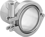
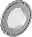
Sights for Quick-Clamp Sanitary Tube Fittings
Gasket, Quick-Clamp Fitting, And
Tube Fitting (All Sold Separately)
Monitor food, brewery, chemical, pharmaceutical, and biotech processing lines with these sights that attach to quick-clamp fittings for fast installation and easy removal for cleaning. All have a one-piece design, so there are no crevices where bacteria can grow. A
For superior strength and reliability, choose 2205 stainless steel sights. All have a glass window that’s melted around a high-strength ring, so they won’t shatter, leak, or lose their shape under high pressure, heat, chemicals, or impact. They withstand harsh cleaners and sanitizers for clean-in-place (CIP) and steam-in-place (SIP) applications. USP Class VI and TUV Rheinland Certified, these sights meet safety standards in the U.S. and Europe. They also meet DIN standards for glass materials used in sights, ASTM standards for materials used in boilers and pressure vessels, and ASME BPE design standards for bioprocessing equipment that ensure purity and safety.
![]() For technical drawings and 3-D models, click on a part number.
For technical drawings and 3-D models, click on a part number.
Temp. Range, °F | ||||||||||
|---|---|---|---|---|---|---|---|---|---|---|
| For Tube OD | For Flange OD | Window Dia. | Max. Pressure | Min. | Max. | For Use With | Features | Specifications Met | Each | |
2205 Stainless Steel Ring with Glass Window | ||||||||||
| 1", 1 1/2" | 1.98" | 1" | 230 psi @ 70° F | -40° | 500° | Water, Hydraulic Fluid, Diesel Fuel, Acetic Acid, Air, Alcohol-Based Solvents, Beverage, Chemicals, Compressed Air, Food, Fuel Oil, Gasoline, Inert Gas, Ketone, Oil, Salt Water, Steam | One-Piece Construction | ASME BPE, ASTM A479, DIN 7079, DIN 7080, TUV Rheinland Certified, USP Class VI | 0000000 | 0000000 |
| 2" | 2.52" | 1 3/16" | 230 psi @ 70° F | -40° | 500° | Water, Hydraulic Fluid, Diesel Fuel, Acetic Acid, Air, Alcohol-Based Solvents, Beverage, Chemicals, Compressed Air, Food, Fuel Oil, Gasoline, Inert Gas, Ketone, Oil, Salt Water, Steam | One-Piece Construction | ASME BPE, ASTM A479, DIN 7079, DIN 7080, TUV Rheinland Certified, USP Class VI | 0000000 | 000000 |
| 3" | 3.58" | 1 1/2" | 150 psi @ 70° F | -40° | 500° | Water, Hydraulic Fluid, Diesel Fuel, Acetic Acid, Air, Alcohol-Based Solvents, Beverage, Chemicals, Compressed Air, Food, Fuel Oil, Gasoline, Inert Gas, Ketone, Oil, Salt Water, Steam | One-Piece Construction | ASME BPE, ASTM A479, DIN 7079, DIN 7080, TUV Rheinland Certified, USP Class VI | 0000000 | 000000 |
| 4" | 4.68" | 2 3/16" | 150 psi @ 70° F | -40° | 500° | Water, Hydraulic Fluid, Diesel Fuel, Acetic Acid, Air, Alcohol-Based Solvents, Beverage, Chemicals, Compressed Air, Food, Fuel Oil, Gasoline, Inert Gas, Ketone, Oil, Salt Water, Steam | One-Piece Construction | ASME BPE, ASTM A479, DIN 7079, DIN 7080, TUV Rheinland Certified, USP Class VI | 0000000 | 000000 |
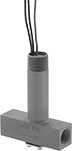
Hazardous Location Flow Switches for Water, Air, and Inert Gas
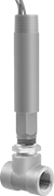
These switches are UL listed for environments with flammable gases and combustible dust. They activate or deactivate equipment when the flow rate reaches your set point. All are single pole, double throw (SPDT) and can be installed to turn one circuit from “off” to “on” (normally open) or from “on” to “off” (normally closed).
Switches with a brass body meet NEC Class I, Divisions 1 and 2, Groups B, C, and D; and NEC Class II, Divisions 1 and 2, Groups E, F, and G.
Switches with a 304 stainless steel body are more corrosion resistant than switches with a brass body and meet NEC Class I, Divisions 1 and 2, Groups A, B, C, and D; and NEC Class II, Divisions 1 and 2, Groups E, F, and G.
![]() For technical drawings and 3-D models, click on a part number.
For technical drawings and 3-D models, click on a part number.
Set Point | Conduit | |||||||||||||
|---|---|---|---|---|---|---|---|---|---|---|---|---|---|---|
| Pipe Size | Thread Type | Gender | For Water, gpm | For Air and Inert Gas, scfm | Max. Pressure | Temp. Range, °F | Voltage | Current | Trade Size | Thread Type | Gender | End-to-End Lg. | Each | |
Brass Body | ||||||||||||||
| 1/2 | NPT | Female | 1.5 | 6.5 | 250 psi @ 70° F | -4° to 220° | 120V AC/ 240V AC | 5 A @ 120 V AC | 3/4 | NPT | Male | 2 1/4" | 00000000 | 0000000 |
| 3/4 | NPT | Female | 2 | 10 | 250 psi @ 70° F | -4° to 220° | 120V AC/ 240V AC | 5 A @ 120 V AC | 3/4 | NPT | Male | 2 3/8" | 00000000 | 000000 |
| 1 | NPT | Female | 3 | 14 | 250 psi @ 70° F | -4° to 220° | 120V AC/ 240V AC | 5 A @ 120 V AC | 3/4 | NPT | Male | 2 1/2" | 00000000 | 000000 |
| 1 1/4 | NPT | Female | 4 | 21 | 250 psi @ 70° F | -4° to 220° | 120V AC/ 240V AC | 5 A @ 120 V AC | 3/4 | NPT | Male | 2 5/8" | 00000000 | 000000 |
| 1 1/2 | NPT | Female | 6 | 33 | 250 psi @ 70° F | -4° to 220° | 120V AC/ 240V AC | 5 A @ 120 V AC | 3/4 | NPT | Male | 2 7/8" | 00000000 | 000000 |
| 2 | NPT | Female | 10 | 43 | 250 psi @ 70° F | -4° to 220° | 120V AC/ 240V AC | 5 A @ 120 V AC | 3/4 | NPT | Male | 3" | 00000000 | 000000 |
304 Stainless Steel Body | ||||||||||||||
| 1/2 | NPT | Female | 1.5 | 6.5 | 2000 psi @ 70° F | -4° to 220° | 120V AC/ 240V AC | 5 A @ 120 V AC | 3/4 | NPT | Male | 2 1/4" | 00000000 | 000000 |
| 3/4 | NPT | Female | 2 | 10 | 2000 psi @ 70° F | -4° to 220° | 120V AC/ 240V AC | 5 A @ 120 V AC | 3/4 | NPT | Male | 2 5/8" | 00000000 | 000000 |
| 1 | NPT | Female | 3 | 14 | 2000 psi @ 70° F | -4° to 220° | 120V AC/ 240V AC | 5 A @ 120 V AC | 3/4 | NPT | Male | 3" | 00000000 | 000000 |
| 2 | NPT | Female | 10 | 43 | 2000 psi @ 70° F | -4° to 220° | 120V AC/ 240V AC | 5 A @ 120 V AC | 3/4 | NPT | Male | 4 3/4" | 00000000 | 00000000 |
Adjustable Hazardous Location Flow Switches for Water, Air, and Inert Gas
For applications with a variable flow rate in environments with flammable gases and combustible dust, these UL-listed switches have an adjustment screw to alter the set point. They activate or deactivate equipment when the flow rate reaches your set point. All are single pole, double throw (SPDT) and can be installed to turn one circuit from “off” to “on” (normally open) or from “on” to “off” (normally closed).
Switch with a brass body meets NEC Class I, Divisions 1 and 2, Groups B, C, and D; and NEC Class II, Divisions 1 and 2, Groups E, F, and G.
Switch with a 304 stainless steel body is more corrosion resistant than the switch with a brass body. It meets NEC Class I, Divisions 1 and 2, Groups A, B, C, and D; and NEC Class II, Divisions 1 and 2, Groups E, F, and G.
![]() For technical drawings and 3-D models, click on a part number.
For technical drawings and 3-D models, click on a part number.
Set Point | Conduit | |||||||||||||
|---|---|---|---|---|---|---|---|---|---|---|---|---|---|---|
| Pipe Size | Thread Type | Gender | For Water, gpm | For Air and Inert Gas, scfm | Max. Pressure | Temp. Range, °F | Voltage | Current | Trade Size | Thread Type | Gender | End-to-End Lg. | Each | |
Brass Body | ||||||||||||||
| 1/2 | NPT | Female | 0.04 to 0.75 | 0.18 to 2.7 | 1450 psi @ 70° F | -4° to 220° | 120V AC/ 240V AC | 5 A @ 120 V AC | 3/4 | NPT | Male | 3 5/8" | 00000000 | 0000000 |
304 Stainless Steel Body | ||||||||||||||
| 1/2 | NPT | Female | 0.04 to 0.75 | 0.18 to 2.7 | 1450 psi @ 70° F | -4° to 220° | 120V AC/ 240V AC | 5 A @ 120 V AC | 3/4 | NPT | Male | 3 5/8" | 00000000 | 000000 |
Hazardous Location Insertion Flow Switches for Water, Oil, Air, and Inert Gas
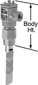
For installation in environments with flammable gases and combustible dust, these flow switches are UL listed for hazardous locations. They meet NEC Class I, Divisions 1 and 2, Groups C and D; and NEC Class II, Divisions 1 and 2, Groups E, F, and G. They’re installed in tees or pipe outlets to detect the flow rate of liquid in contact with the sensing paddle. Switches activate or deactivate equipment when the flow rate reaches your set point. All come with five sensing paddles that can be trimmed to fit a range of pipe sizes. The flow rate varies based on the pipe size and paddle used.
SPDT switches control one circuit. They can be installed to turn the circuit from “off” to “on” (normally open) or from “on” to “off” (normally closed).
DPDT switches control two circuits. They can be installed to turn both circuits from “off” to “on” (normally open) or from “on” to “off” (normally closed).
Switches with a 316 stainless steel body are more corrosion resistant than switches with a brass body.
![]() For technical drawings and 3-D models, click on a part number.
For technical drawings and 3-D models, click on a part number.
Set Point | Conduit | ||||||||||||||
|---|---|---|---|---|---|---|---|---|---|---|---|---|---|---|---|
| Pipe Size | Thread Type | Gender | For Pipe Size | For Water and Oil, gpm | For Air and Inert Gas, scfm | Max. Pressure | Temp. Range, °F | Voltage | Current | Trade Size | Thread Type | Gender | Body Ht. | Each | |
SPDT | |||||||||||||||
Brass Body | |||||||||||||||
| 1 1/2 | NPT | Male | 1 1/2 to 20 | 3 to 2,400 | 17 to 10,000 | 1000 psi @ 70° F | -4° to 275° | 120V AC 240V AC | 10 A @ 120 V AC | 3/4 | NPT | Female | 8" | 00000000 | 0000000 |
316 Stainless Steel Body | |||||||||||||||
| 1 1/2 | NPT | Male | 1 1/2 to 20 | 3 to 2,400 | 17 to 10,000 | 2000 psi @ 70° F | -4° to 275° | 120V AC 240V AC | 10 A @ 120 V AC | 3/4 | NPT | Female | 8" | 00000000 | 000000 |
DPDT | |||||||||||||||
Brass Body | |||||||||||||||
| 1 1/2 | NPT | Male | 1 1/2 to 20 | 3 to 2,400 | 17 to 10,000 | 1000 psi @ 70° F | -4° to 275° | 120V AC 240V AC | 10 A @ 120 V AC | 3/4 | NPT | Female | 8" | 00000000 | 000000 |
316 Stainless Steel Body | |||||||||||||||
| 1 1/2 | NPT | Male | 1 1/2 to 20 | 3 to 2,400 | 17 to 10,000 | 2000 psi @ 70° F | -4° to 275° | 120V AC 240V AC | 10 A @ 120 V AC | 3/4 | NPT | Female | 8" | 00000000 | 000000 |
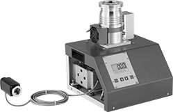
Electric Ultra-High-Vacuum Pumps
Achieve vacuum levels up to 1 x 10 -12 torr with these ultra-high-vacuum pumps. Each unit includes two pumps—a diaphragm pump and a turbomolecular pump—that work together to create extremely high levels of vacuum in your chamber. The turbomolecular pump meets IP54 for protection in damp and dusty environments. Units are compact, so they fit on top of a workbench or table.
Pumps are ready to use as soon as they’re plugged in and connected to a chamber. Since they don’t use oil, they won’t introduce contaminants into your system. They hardly vibrate, minimizing interference with sensitive instruments and measurement devices.
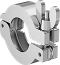
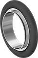
Pumps with claw-clamp intake connections require a ring and four double-claw clamps (all sold separately) to connect to other components. Claw-clamp connections are also known as ISO-K fittings. These pumps include a gauge with quick-clamp connections, which requires a quick clamp and a ring (both sold separately) to connect. Quick-clamp connections are also known as KF fittings.
Pumps with flanged intake connections and the included gauge each require a gasket (sold separately) to connect to your chamber. Flanged connections are also known as CF fittings.
Intake Connection | Gauge Port Connection | Discharge Connection (BSPP Threads) | O'all | ||||||||||||||
|---|---|---|---|---|---|---|---|---|---|---|---|---|---|---|---|---|---|
| Max. Vacuum | Max. Flow Rate, cfm | Volume, dBA | Current, A | For Tube OD | Flange OD | High-Vacuum Flange Size | High Vacuum Connection Type | For Tube OD | Flange OD | High-Vacuum Flange Size | High Vacuum Connection Type | Pipe Size | Gender | Ht. | Wd. | Each | |
Claw-Clamp Intake Connection—120V AC/240V AC, Single Phase | |||||||||||||||||
| 1 × 10 -8 torr @ 72° F | 142 | 50 | 4.6 | 2 1/2" | 3 3/4" | 63 | ISO-K | 1" | 1.57" | 25 | ISO-KF | 1/8 | Male | 13 5/8" | 11 7/8" | 000000 | 000000000 |
Flanged Intake Connection—120V AC/240V AC, Single Phase | |||||||||||||||||
| 1 × 10 -12 torr @ 72° F | 142 | 50 | 4.6 | 2 1/2" | 4 1/2" | 63 | CF | 1 1/2" | 2 3/4" | 40 | CF | 1/8 | Male | 13 7/8" | 11 7/8" | 000000 | 00000000 |
| For Tube OD | For Flange OD | For High-Vacuum Flange Size | High Vacuum Connection Type | Material | Max. Vacuum | Each | |
For Claw-Clamp Intake Connection—Double-Claw with Bolt | |||||||
|---|---|---|---|---|---|---|---|
| 2 1/2", 3", 4" | 3.74", 4.33", 5.12" | 63, 80, 100 | ISO-K | Aluminum | 1 × 10 -9 torr @ 72° F | 0000000 | 00000 |
For Quick-Clamp Gauge Connection—Clamp with Wing Nut | |||||||
| 1" | 1.57" | 25 | ISO-KF | Aluminum | 1 × 10 -7 torr @ 72° F | 0000000 | 00000 |
Material | |||||||||
|---|---|---|---|---|---|---|---|---|---|
| For Tube OD | For Flange OD | For High-Vacuum Flange Size | High Vacuum Connection Type | O-Ring | Inner Ring | Max. Vacuum | Max. Temp., °F | Each | |
For Claw-Clamp Intake Connection | |||||||||
| 2 1/2" | 3.74" | 63 | ISO-K | Viton® Fluoroelastomer Rubber | 304 Stainless Steel | 1 × 10 -9 torr @ 72° F | 400° | 0000000 | 000000 |
For Quick-Clamp Gauge Connection | |||||||||
| 1" | 1.57" | 25 | ISO-KF | Fluoroelastomer Rubber | 304 Stainless Steel | 1 × 10 -7 torr @ 72° F | 300° | 0000000 | 0000 |