


Scale Scale | Show |
|---|
|
Scale Scale | Hide |
|---|
For Use With For Use With |
|---|
|
|
Display Type Display Type |
|---|
 | |
| Dial | Digital |
 |  |
| U-Tube | Inclined Scale |
Dial Type Dial Type |
|---|
 | Dry |
Measures Measures |
|---|
|
Connection Location Connection Location |
|---|
| Bottom | Center Back | ||
System of Measurement System of Measurement |
|---|
|


Case Material Case Material |
|---|
|
Connection Material Connection Material |
|---|
|
Connection Style Connection Style |
|---|
| Barbed |
 |
| Compression |
 |
| Threaded |
Accuracy Grade Accuracy Grade |
|---|
|
|
Maximum Pressure, in. of H2O Maximum Pressure, in. of H2O |
|---|
|
Maximum Pressure Maximum Pressure |
|---|
Accuracy Scale Accuracy Scale |
|---|
|
RoHS (Restriction of Hazardous Substances) RoHS (Restriction ofHazardous Substances) |
|---|
|
REACH (Registration, Evaluation, Authorization and Restriction of Chemicals) REACH (Registration,Evaluation, Authorization and Restriction of Chemicals) |
|---|
|
About Pressure Gauges
More
About Pipe Size
More
About Pressure Transmitters
More
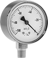
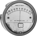
High-Accuracy Low-Pressure Gauges
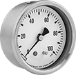
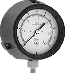

Measure small pressure changes in ventilation systems, hydraulic applications, and other critical processes with these high-accuracy gauges. Mount them with the dial face upright.
Gauges with 304 stainless steel case or polyester plastic case have better corrosion resistance than gauges with steel case.
Gauges with safety case blow out in the back under excess pressure, protecting the operator in front.
![]() For technical drawings and 3-D models, click on a part number.
For technical drawings and 3-D models, click on a part number.
- For Use With: Air, Water, Hydraulic Fluid, Carbon Dioxide, and Natural Gas
- Accuracy: ±1.5% Full Scale (Not Graded)
Available Pressure Gauges | ||
|---|---|---|
| Pressure Range, in. of H₂O | Graduation Marks, in. of H₂O | Numeric Increments, in. of H₂O |
| 0 to 10 | 0.2 | 2 |
| 0 to 15 | 0.2 | 3 |
| 0 to 30 | 0.5 | 5 |
| 0 to 60 | 1 | 10 |
| 0 to 100 | 2 | 20 |
| 0 to 160 | 4 | 40 |
| 0 to 200 | 4 | 40 |
Bottom Connection | Center Back Connection | ||||||||
|---|---|---|---|---|---|---|---|---|---|
| Dial Diameter | Pipe Size | Environment Temp. Range, °F | Process Temp. Range, °F | Case Color | Mounting Orientation | Each | Each | ||
NPT Male | |||||||||
| 2 1/2" | 1/4 | 0° to 140° | 0° to 140° | Black | Upright | 0000000 | 000000 | 0000000 | 000000 |
NPT Male with Calibration Certificate Traceable to NIST | |||||||||
| 2 1/2" | 1/4 | 0° to 140° | 0° to 140° | Black | Upright | 0000000 | 000000 | 0000000 | 000000 |
- For Use With: Air, Water, Hydraulic Fluid, Carbon Dioxide, and Natural Gas
- Accuracy: ±1% Full Scale (Grade 1A)
Available Pressure Gauges | ||
|---|---|---|
| Pressure Range, in. of H₂O | Graduation Marks, in. of H₂O | Numeric Increments, in. of H₂O |
| 0 to 10 | 0.2 | 2 |
| 0 to 15 | 0.2 | 3 |
| 0 to 30 | 0.5 | 5 |
| 0 to 60 | 1 | 10 |
| 0 to 100 | 2 | 20 |
| 0 to 160 | 2 | 20 |
| 0 to 200 | 4 | 40 |
Bottom Connection | ||||||
|---|---|---|---|---|---|---|
| Dial Diameter | Pipe Size | Environment Temp. Range, °F | Process Temp. Range, °F | Mounting Orientation | Each | |
NPT Male | ||||||
| 4" | 1/4 | 0° to 140° | 0° to 140° | Upright | 000000 | 0000000 |
- For Use With: Air, Argon, Nitrogen, and Natural Gas
- Accuracy: ±1% Mid Scale (Grade A)
Available Pressure Ranges | |||||
|---|---|---|---|---|---|
Pressure Range | Graduation Marks | Numeric Increments | |||
| in. of H₂O | oz./in.2 | in. of H₂O | oz./in.2 | in. of H₂O | oz./in.2 |
| 0 to 10 | 0 to 6 | 0.1 | 0.1 | 1 | 1 |
| 0 to 15 | 0 to 9 | 0.2 | 0.1 | 3 | 1 |
| 0 to 20 | 0 to 12 | 0.2 | 0.1 | 2 | 1 |
| 0 to 30 | 0 to 18 | 0.2 | 0.2 | 5 | 2 |
| 0 to 40 | 0 to 24 | 0.5 | 0.2 | 5 | 2 |
| 0 to 60 | 0 to 35 | 1 | 0.5 | 10 | 5 |
| 0 to 80 | 0 to 45 | 1 | 0.5 | 10 | 5 |
| 0 to 100 | 0 to 57 | 1 | 1 | 10 | 10 |
| 0 to 150 | 0 to 90 | 2 | 1 | 30 | 10 |
Mounting | Bottom Connection (Flange Mount) | ||||||||||
|---|---|---|---|---|---|---|---|---|---|---|---|
| Dial Diameter | Pipe Size | Environment Temp. Range, °F | Process Temp. Range, °F | Case Color | Orientation | Fasteners Included | Hole Dia. | No. of Holes | Features | Each | |
NPT Male | |||||||||||
| 4 1/2" | 1/4 | 0° to 140° | -40° to 210° | Black | Upright | No | 1/4" | 3 | Safety Case | 000000 | 0000000 |
Ultra-Low Vacuum Gauges
Accommodate applications with very low vacuum with these gauges. Use them with vacuum pumps, packaging equipment, and in suction lines to measure and display vacuum.
Gauges with 304 stainless steel case have better corrosion resistance than gauges with steel case.
![]() For technical drawings and 3-D models, click on a part number.
For technical drawings and 3-D models, click on a part number.
- For Use With: Air
- Accuracy: ±1.6% Full Scale (Not Graded)
Available Vacuum Ranges | ||
|---|---|---|
| Vacuum Range, in. of H₂O | Graduation Marks, in. of H₂O | Numeric Increments, in. of H₂O |
| -100 to 0 | 2 | 20 |
| -60 to 0 | 1 | 10 |
| -30 to 0 | 0.5 | 5 |
| -15 to 0 | 0.2 | 3 |
- For Use With: Air
- Accuracy: ±1% Full Scale (Not Graded)
Available Vacuum Ranges | ||
|---|---|---|
| Vacuum Range, in. of H₂O | Graduation Marks, in. of H₂O | Numeric Increments, in. of H₂O |
| -100 to 0 | 2 | 20 |
| -60 to 0 | 1 | 10 |
| -30 to 0 | 0.5 | 5 |
| -15 to 0 | 0.2 | 3 |
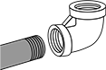
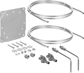
Low-Pressure Differential Gauges with Dial Indicator
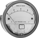
Measure small changes in air pressure with these gauges. They are commonly used to indicate clogged filters and to monitor fans and blowers.
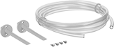
Service these gauges without removing them using air filter kits. Kits include two vent valves for releasing air.
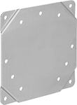
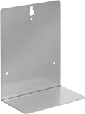
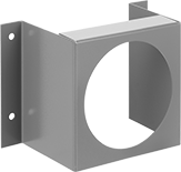
Surface mounting brackets allow gauges to be quickly installed on any flat surface. L mounting brackets can be carried to wherever you need to take a pressure reading. They can stand alone or be hung. Wraparound mounting brackets make it easy to service tubing, and don’t require cutting a hole in the wall.
![]() For technical drawings and 3-D models, click on a part number.
For technical drawings and 3-D models, click on a part number.
- For Use With: Air
- Accuracy: ±2% Full Scale (Not Graded); except
0" to 0.25" in. of H2O: ±4% Full Scale (Not Graded)
0" to 0.5" in. of H2O: ±3% Full Scale (Not Graded)
Available Pressure Ranges | ||
|---|---|---|
| Pressure Range, in. of H₂O | Graduation Marks, in. of H₂O | Numeric Increments, in. of H₂O |
| 0 to 0.25 | 0.005 | 0.05 |
| 0 to 0.5 | 0.01 | 0.1 |
| 0 to 1 | 0.02 | 0.2 |
| 0 to 2 | 0.05 | 0.25 |
| 0 to 3 | 0.1 | 1 |
| 0 to 4 | 0.1 | 1 |
| 0 to 5 | 0.1 | 1 |
| 0 to 6 | 0.2 | 1 |
| 0 to 8 | 0.2 | 2 |
| 0 to 10 | 0.2 | 2 |
| 0 to 15 | 0.5 | 5 |
| 0 to 20 | 0.5 | 5 |
| 0 to 25 | 0.5 | 5 |
| 0 to 30 | 1 | 10 |
| 0 to 40 | 1 | 5 |
| 0 to 50 | 1 | 10 |
| 0 to 80 | 2 | 20 |
| 0 to 100 | 2 | 20 |
| 0 to 150 | 5 | 50 |
| Dial Diameter | Pipe Size | Max. Pressure, psi | Environment Temp. Range, °F | Process Temp. Range, °F | Features | Includes | Each | |
NPT Female | ||||||||
|---|---|---|---|---|---|---|---|---|
| 4" | 1/8 | 15 | 20° to 140° | 20° to 140° | Two Inlets and Two Outlets | Plugs for Unused Ports | 0000000 | 000000 |
NPT Female with NIST Certificate | ||||||||
| 4" | 1/8 | 15 | 20° to 140° | 20° to 140° | Two Inlets and Two Outlets | Plugs for Unused Ports | 0000000 | 000000 |
| Includes | Each | |
| 9-ft. Lg. × 3/16" ID Tubing Carrying Case Mounting Bracket Two Pipe-to-Tube Adapters | 0000000 | 000000 |
| Includes | Each | |
| Mounting Bracket Mounting Fasteners Two 5-ft. Lg. Aluminum Tubing Two Pressure Tips Two Vent Valves | 0000000 | 000000 |
| Includes | Each | |
| 7-ft. Lg. PVC Tubing Two Pressure Tips | 0000000 | 00000 |
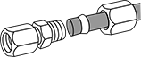
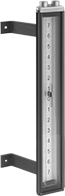
Low-Pressure Differential Gauges with U-Tube
Also known as manometers, these gauges come with indicating liquid that moves up and down two columns—the difference in height between them is your pressure. They are commonly used to indicate clogged filters.
Magnet-mount gauges can be moved for use in multiple locations. Gauges with barbed tube connection have a flexible body that rolls up for storage or transport.
- For Use With: Acetylene, Air, Argon, Carbon Dioxide, and Steam
- Accuracy: Not Rated (Not Graded)
Environment Temp. Range | Process Temp. Range | Mounting | ||||||||||||||
|---|---|---|---|---|---|---|---|---|---|---|---|---|---|---|---|---|
| Pressure Range, in. of H₂O | Scale Range, in. of H₂O | Numeric Increments, in. of H₂O | Graduation Marks, in. of H₂O | Max. Pressure, psi | Ht. | Min., °F | Max., °F | Min., °F | Max., °F | Gender | Mount Type | Fasteners Included | Hole Dia. | Number of Holes | Each | |
With 1/4 NPT Female Threaded Pipe Connection | ||||||||||||||||
| 0-10 | 5-0-5 | 1 | 0.1 | 250 | 14" | 35° | 150° | 35° | 250° | Female | Screw On | No | 3/16" | 4 | 0000000 | 0000000 |
| 0-15 | 7-0-7 | 1 | 0.1 | 250 | 18" | 35° | 150° | 35° | 250° | Female | Screw On | No | 3/16" | 4 | 0000000 | 000000 |
- For Use With: Air, Argon, Carbon Dioxide, and Hydrogen
- Accuracy: Not Rated (Not Graded)
| Pressure Range, in. of H₂O | Scale Range, in. of H₂O | Numeric Increments, in. of H₂O | Graduation Marks, in. of H₂O | Max. Pressure | Ht. | Max. Process Temp., °F | Gender | Mount Type | Each | |
With Barbed Tube Connection for 3/16" Tube ID | ||||||||||
|---|---|---|---|---|---|---|---|---|---|---|
| 0-8 | 4-0-4 | 1 | 0.1 | Not Rated | 17" | 130° | Male | Magnet | 0000000 | 0000000 |
| 0-12 | 6-0-6 | 1 | 0.1 | Not Rated | 21" | 130° | Male | Magnet | 0000000 | 000000 |
| 0-16 | 8-0-8 | 1 | 0.1 | Not Rated | 25" | 130° | Male | Magnet | 0000000 | 000000 |
| 0-24 | 12-0-12 | 1 | 0.1 | Not Rated | 33" | 130° | Male | Magnet | 0000000 | 000000 |
| 0-30 | 15-0-15 | 1 | 0.1 | Not Rated | 39" | 130° | Male | Magnet | 0000000 | 000000 |
| 0-36 | 18-0-18 | 1 | 0.1 | Not Rated | 45" | 130° | Male | Magnet | 0000000 | 000000 |
| 0-48 | 24-0-24 | 1 | 0.1 | Not Rated | 57" | 130° | Male | Magnet | 0000000 | 000000 |
| 0-60 | 30-0-30 | 1 | 0.1 | Not Rated | 69" | 130° | Male | Magnet | 0000000 | 000000 |
| 0-72 | 36-0-36 | 1 | 0.1 | Not Rated | 81" | 130° | Male | Magnet | 0000000 | 000000 |
- For Use With: Air, Argon, Carbon Dioxide, and Hydrogen
- Accuracy: Not Rated (Not Graded)
| Pressure Range, in. of H₂O | Scale Range, in. of H₂O | Numeric Increments, in. of H₂O | Graduation Marks, in. of H₂O | Max. Pressure, psi | Ht. | Gender | Mount Type | Each | |
With Compression Tube Connection for 1/4" Tube OD | |||||||||
|---|---|---|---|---|---|---|---|---|---|
| 0-8 | 4-0-4 | 1 | 0.1 | 100 | 20" | Female | Magnet | 0000000 | 0000000 |
| 0-12 | 6-0-6 | 1 | 0.1 | 100 | 25" | Female | Magnet | 0000000 | 000000 |
| 0-16 | 8-0-8 | 1 | 0.1 | 100 | 30" | Female | Magnet | 0000000 | 000000 |
| 0-20 | 10-0-10 | 1 | 0.1 | 100 | 34" | Female | Magnet | 0000000 | 000000 |
| 0-24 | 12-0-12 | 1 | 0.1 | 100 | 39" | Female | Magnet | 0000000 | 000000 |
| 0-36 | 18-0-18 | 1 | 0.1 | 100 | 58" | Female | Magnet | 0000000 | 000000 |
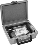
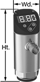
Low-Pressure Differential Gauges with Digital Display
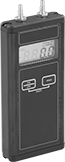
Measure small changes in air pressure with these hand-held gauges. They have a four-digit LCD display for easy reading of measurements. Gauges are commonly used to indicate clogged filters and to monitor fans and blowers.
- For Use With: Air, Natural Gas
- Accuracy: ±0.5% Full Scale (Not Graded)
Pressure Range | |||||||||||||
|---|---|---|---|---|---|---|---|---|---|---|---|---|---|
| kPa | in. of H₂O | Resolution, in. of H₂O | Max. Pressure, psi | For Tube ID | Environment Temp. Range, °F | Process Temp. Range, °F | Digit Ht. | Ht. | Wd. | Batteries Included | Environmental Rating | Each | |
Barbed Tube Connection | |||||||||||||
| 0-4.982 | 0-20 | 0.01 | 10 | 1/8"-3/16" | 35° to 100° | 0° to 140° | 3/8" | 6 1/2" | 2 13/16" | Yes | NEC Class I Division 2 Groups A, B, C, D | 0000000 | 0000000 |
| 0-49.82 | 0-200 | 0.1 | 30 | 1/8"-3/16" | 35° to 100° | 0° to 140° | 3/8" | 6 1/2" | 2 13/16" | Yes | NEC Class I Division 2 Groups A, B, C, D | 0000000 | 000000 |
Barbed Tube Connection with Calibration Certificate Traceable to NIST | |||||||||||||
| 0-4.982 | 0-20 | 0.01 | 10 | 1/8"-3/16" | 35° to 100° | 0° to 140° | 3/8" | 6 1/2" | 2 13/16" | Yes | NEC Class I Division 2 Groups A, B, C, D | 0000000 | 000000 |
| 0-49.82 | 0-200 | 0.1 | 30 | 1/8"-3/16" | 35° to 100° | 0° to 140° | 3/8" | 6 1/2" | 2 13/16" | Yes | NEC Class I Division 2 Groups A, B, C, D | 0000000 | 000000 |
| Optional Nylon Carrying Case | 0000000 | Each | 000000 |
Low-Pressure Differential Gauges with Inclined Scale
Easier to read than U-tube gauges, these use an inclined scale to measure pressure or velocity in air applications. Gauges are also known as manometers.
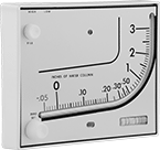
- For Use With: Air
- Accuracy: ±3% Full Scale (Not Graded)
Indicating Liquid | ||||||||||
|---|---|---|---|---|---|---|---|---|---|---|
| Pressure Range, in. of H₂O | Max. Pressure, psi | Max. Process Temp. Range, °F | Ht. | Color | Specific Gravity | Mount Type | Mounting Fasteners Included | Includes | Each | |
With Barbed Tube Connection for 3/16" Tube ID | ||||||||||
| 0-3 | 10 | 140° | 6" | Red | 0.826 | Screw On | Yes | 8-ft. Lg. Tubing; Indicating Liquid | 000000 | 000000 |
| 0-7 | 10 | 140° | 6" | Blue | 1.91 | Screw On | Yes | 8-ft. Lg. Tubing; Indicating Liquid | 000000 | 000000 |
Differential Pressure and Vacuum Gauges
Commonly used to indicate clogged filters, these gauges display the difference between two pressure or vacuum measurements. They are also known as compound gauges.
![]() For technical drawings and 3-D models, click on a part number.
For technical drawings and 3-D models, click on a part number.
- For Use With: Air
- Accuracy: ±2% Mid Scale (Not Graded); except
0 to 0.2" in. of H2O: ±4% Mid Scale (Not Graded)
0 to 0.25" in. of H2O: ±3% Mid Scale (Not Graded)
Available Pressure and Vacuum Ranges | |||
|---|---|---|---|
| Pressure Range, in. of H₂O | Vacuum Range, in. of H₂O | Graduation Marks, in. of H₂O | Numeric Increments, in. of H₂O |
| 0 to 0.2" | -0.05" to 0 | 0.01 | 0.05 |
| 0 to 0.25" | -0.25" to 0 | 0.01 | 0.05 |
| 0 to 0.5" | -0.5" to 0 | 0.02 | 0.1 |
| 0 to 1" | -1" to 0 | 0.05 | 0.25 |
| 0 to 5" | -5" to 0 | 0.2 | 1 |
| 0 to 10" | -10" to 0 | 0.5 | 5 |
| 0 to 15" | -15" to 0 | 1 | 5 |
| Dial Diameter | Pipe Size | Max. Pressure, psi | Environment Temp. Range, °F | Process Temp. Range, °F | Features | Includes | Each | |
NPT Female | ||||||||
|---|---|---|---|---|---|---|---|---|
| 4" | 1/8 | 15 | 20° to 140° | 20° to 140° | Two Inlets and Two Outlets | Plugs for Unused Ports | 00000000 | 000000 |
NPT Female with NIST Certificate | ||||||||
| 4" | 1/8 | 15 | 20° to 140° | 20° to 140° | Two Inlets and Two Outlets | Plugs for Unused Ports | 0000000 | 000000 |
Differential Pressure and Vacuum Gauges with Digital Display
Gauges have a four-digit LCD display for easy reading of measurements. Commonly used to indicate clogged filters, these gauges display the difference between two pressure or vacuum measurements. They are also known as compound gauges.
- For Use With: Air
- Accuracy: ±0.5% Full Scale (Not Graded)
Pressure Range | ||||||||||||||
|---|---|---|---|---|---|---|---|---|---|---|---|---|---|---|
| psi | kPa | in. of H₂O | mbar | Vacuum Range, in. of Hg | Resolution, in. of H₂O | Max. Pressure, psi | For Tube ID | Environment Temp. Range, °F | Process Temp. Range, °F | Digit Ht. | Batteries Included | Features | Each | |
Barbed Tube Connection | ||||||||||||||
| 0-0.723 | 0-4.982 | 0-20" | 0-49.82 | 1.471"-0 | 0.01 | 10 | 1/8"-3/16" | 35° to 100° | 0° to 140° | 3/8" | Yes | 40-Reading Memory, Overpressure Alarm | 0000000 | 0000000 |
| 0-7.225 | 0-49.82 | 0-200" | 0-498.2 | 14.71"-0 | 0.1 | 30 | 1/8"-3/16" | 35° to 100° | 0° to 140° | 3/8" | Yes | 40-Reading Memory, Overpressure Alarm | 0000000 | 000000 |
| 0-20 | 0-137.9 | 0-553" | 0-1,379 | 40.72"-0 | 0.01 | 60 | 1/8"-3/16" | 35° to 100° | 0° to 140° | 3/8" | Yes | 40-Reading Memory, Overpressure Alarm | 0000000 | 000000 |
Barbed Tube Connection with Calibration Certificate Traceable to NIST | ||||||||||||||
| 0-0.723 | 0-4.982 | 0-20" | 0-49.82 | 1.471"-0 | 0.01 | 10 | 1/8"-3/16" | 35° to 100° | 0° to 140° | 3/8" | Yes | 40-Reading Memory, Overpressure Alarm | 0000000 | 000000 |
| 0-7.225 | 0-49.82 | 0-200" | 0-498.2 | 14.71"-0 | 0.1 | 30 | 1/8"-3/16" | 35° to 100° | 0° to 140° | 3/8" | Yes | 40-Reading Memory, Overpressure Alarm | 0000000 | 000000 |
| 0-20 | 0-137.9 | 0-553" | 0-1,379 | 40.72"-0 | 0.01 | 60 | 1/8"-3/16" | 35° to 100° | 0° to 140° | 3/8" | Yes | 40-Reading Memory, Overpressure Alarm | 0000000 | 000000 |
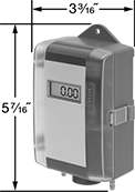
Pressure and Vacuum Transmitters with Digital Display
- For Use With: Air, Argon, Diesel Fuel, Hydraulic Fluid, Nitrogen, Water
- Accuracy: ±1%
- Pipe Connection Type: Threaded
- Housing Material: Glass-Reinforced Polyester
- Connection Material: 316L Stainless Steel
- Temperature Range: -10° to 175°F
Monitor and control vacuum pumps, air compressors, and hydraulics while viewing readings and warnings on the display. These transmitters, also called transducers, have two outputs, so you can program them to work as a transmitter, a switch, or both. When they reach their setpoint, they send electrical signals to your programmable logic controller (PLC) to trigger actions in your system. Adjust their reset point anywhere within the setpoint range. To change settings and receive error messages remotely from your PLC or computer, program one of the outputs to use IO Link. You need an IO-Link controller (not included) to connect to your interface.
Buttons on the display let you change your setpoint, measuring range, and other settings. To quickly tell the status of your process, you can program the color of the display to red and green. LEDs on the corners also notify you of your output’s switching status. Rotate the head to view the display from the best angle.
You must calibrate your PLC in order for it to interpret signals from these transmitters. As pressure increases, the output signal from the transmitter will increase. These transmitters only give accurate readings within the rated pressure or vacuum range.
All have an M12 plug to connect to M12 Connectors. When using both switching outputs and an IO-Link controller, they require four wires to connect. For their 4-20mA analog output, they need two wires to connect. View switch wiring diagrams by selecting a part number and clicking Product Detail.
To withstand wet environments, these transmitters have a 316L stainless steel connection and are IP rated. Their IP ratings also mean they’re dust tight and stand up to spraying water and brief submersion. UL and C-UL listed as well as CE marked, they meet strict American, Canadian, and European safety standards.
![]() For technical drawings and 3-D models, click on a part number.
For technical drawings and 3-D models, click on a part number.
Setpoint Range | Configurable Analog Transmitter/Digital Switch Output | Configurable Digital Switch Output | ||||||||||||||
|---|---|---|---|---|---|---|---|---|---|---|---|---|---|---|---|---|
| Pressure Range, psi | Vacuum Range, in. of Hg | Max. Continuous and Short-Term Pressure, psi | Pressure, psi | Vacuum, in. of Hg | Input Voltage | Pipe Size | Ht. | Wd. | No. of | Current | Signal Type | No. of | Signal Type | Scale | Each | |
NPT Female | ||||||||||||||||
| 0-14.5 | 29.5-0 | 145 | 0-14.5 | 29.5-0 | 18-30V DC | 1/4 | 3 9/16" | 1 3/8" | 1 | 4-20mA | NPN, PNP | 1 | NPN, PNP | in. of H2O, in. of Hg, kPa, mbar, psi | 0000000 | 0000000 |
NPT Male | ||||||||||||||||
| 0-14.5 | 29.5-0 | 145 | 0-14.5 | 29.5-0 | 18-30V DC | 1/4 | 3 9/16" | 1 3/8" | 1 | 4-20mA | NPN, PNP | 1 | NPN, PNP | in. of H2O, in. of Hg, kPa, mbar, psi | 0000000 | 000000 |
BSPP Female | ||||||||||||||||
| 0-7.3 | 14.8-0 | 145 | 0-7.3 | 14.8-0 | 18-30V DC | 1/4 | 3 9/16" | 1 3/8" | 1 | 4-20mA | NPN, PNP | 1 | NPN, PNP | in. of H2O, kPa, mbar, psi | 0000000 | 000000 |
| 0-14.5 | 1.4-0 | 145 | 0-14.5 | 1.4-0 | 18-30V DC | 1/4 | 3 9/16" | 1 3/8" | 1 | 4-20mA | NPN, PNP | 1 | NPN, PNP | in. of H2O, kPa, mbar, psi | 0000000 | 000000 |
| 0-14.5 | 29.5-0 | 145 | 0-14.5 | 29.5-0 | 18-30V DC | 1/4 | 3 9/16" | 1 3/8" | 1 | 4-20mA | NPN, PNP | 1 | NPN, PNP | in. of H2O, in. of Hg, kPa, mbar, psi | 0000000 | 000000 |
BSPP Male | ||||||||||||||||
| 0-14.5 | 29.5-0 | 145 | 0-14.5 | 29.5-0 | 18-30V DC | 1/4 | 3 11/16" | 1 3/8" | 1 | 4-20mA | NPN, PNP | 1 | NPN, PNP | in. of H2O, in. of Hg, kPa, mbar, psi | 0000000 | 000000 |
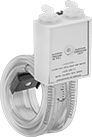
Low-Pressure Differential Pressure Transmitters
- For Use With: Air, Argon, Nitrogen
- Accuracy: ±1%
- Tube Connection Type: Barbed
- Housing Material: Polycarbonate
- Temperature Range: 32° to 122° F
These transmitters are commonly used to monitor airflow and to indicate when filters in HVAC systems become clogged. They convert the difference in pressure between two points in a low-pressure system into an electrical signal that can be interpreted by receiving devices, such as remote displays, programmable logic controllers, and motor speed controls to monitor pressure or control equipment. Transmitters will only provide accurate readings within the rated pressure range. They come with a calibration certificate traceable to NIST. Maximum pressure is the maximum spike in pressure a transmitter can withstand without damage. Transmitters are accurate only within the pressure range, not up to the maximum pressure. All transmitters are rated IP67 for protection in washdown environments.
These transmitters connect using three wires—two wires into the power supply and a separate wire that sends a voltage signal to the receiver. The receiver and the transmitter share a common ground wire back to the power supply.
Mounting Holes | Transmitters with Calibration Certificate Traceable to NIST | |||||||||||
|---|---|---|---|---|---|---|---|---|---|---|---|---|
| Pressure Range, in. of H2O | Max. Pressure, psi | Input Voltage | For Tube ID | For No. of Wires | For DIN Rail Ht., mm | Mounting Hardware Included | Dia. | No. of | Ht. | Wd. | Each | |
0-10V DC Voltage Output—Screw Terminals | ||||||||||||
Surface Mount | ||||||||||||
| -0.5 to 0.5, -1 to 1, -2.5 to 2.5, -5 to 5 | 10 | 13-30V DC | 3/16" | 3 | __ | No | 3/16" | 2 | 5 7/16" | 3 3/16" | 0000000 | 0000000 |
DIN Rail or Surface Mount | ||||||||||||
| -0.5 to 0.5, -1 to 1, -2.5 to 2.5, -5 to 5 | 10 | 13-30V DC | 3/16" | 3 | 35 | No | 3/16" | 2 | 5 7/16" | 3 3/16" | 0000000 | 000000 |
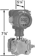
Easy-Setup Differential Pressure Transmitters

- For Use With: Air, Argon, Hydraulic Fluid, Nitrogen, Water
- Accuracy: ±0.075%
- Pipe Connection: NPT Female
- Housing Material: Aluminum
- Connection Material: Hastelloy
- Temperature Range: -40° to 185° F
Measure the difference in pressure between two process lines in flow applications such as heat exchangers, chillers, and pumps. These transmitters automatically compensate for error introduced by vibration as well as temperature fluctuations, so you do not need to program your receiving device to correct for these factors. Use the keypad to set the pressure range, choose the unit of measure, and zero the transmitter. These transmitters convert differential pressure to an electrical signal that can be interpreted by receiving devices, such as remote displays, programmable logic controllers, and motor speed controls to monitor pressure or control equipment. Transmitters will only provide accurate readings within the rated pressure range. Maximum pressure is the maximum spike in pressure a transmitter can withstand without damage. Transmitters are accurate only within the pressure range, not up to the maximum pressure. All transmitters meet IP66 and NEMA 4X for use in washdown and corrosive environments and have a hastelloy diaphragm to resist harsh chemicals.
These transmitters typically connect using two wires to send a 4-20mA current output. The same wire is used to send a signal to the receiver and to power the transmitter. Current doesn’t lose signal over long distances and isn’t affected by electrical interference from other devices. They can also be configured using three or four wires.
![]() For technical drawings and 3-D models, click on a part number.
For technical drawings and 3-D models, click on a part number.
Mounting Holes | |||||||||||||
|---|---|---|---|---|---|---|---|---|---|---|---|---|---|
| Pressure Range | Max. Pressure, psi | Input Voltage | Pipe Size | For No. of Wires | Mounting Hardware Included | Dia. | No. of | Ht. | Wd. | Communication Protocol | Environmental Rating | Each | |
4-20mA Current Output—Screw Terminals | |||||||||||||
| 0-24 in. of H2O | 3,625 | 11-55V DC | 1/4 | 2, 3, 4 | No | 7/16" | 8 | 7 7/8" | 5 1/4" | HART | IP66, NEMA 4X | 0000000 | 000000000 |
| 0-160 in. of H2O | 5,800 | 11-55V DC | 1/4 | 2, 3, 4 | No | 7/16" | 8 | 7 7/8" | 5 1/4" | HART | IP66, NEMA 4X | 0000000 | 00000000 |
| 0-1,000 in. of H2O | 5,800 | 11-55V DC | 1/4 | 2, 3, 4 | No | 7/16" | 8 | 7 7/8" | 5 1/4" | HART | IP66, NEMA 4X | 0000000 | 00000000 |
Hazardous Location Easy-Setup Differential Pressure Transmitters
- For Use With: Air, Argon, Hydraulic Fluid, Nitrogen, Water
- Accuracy: ±0.075%
- Pipe Connection: NPT Female
- Housing Material: Aluminum
- Connection Material: Hastelloy
- Temperature Range: -40° to 185° F
For use in hazardous locations, these transmitters safely measure the difference in pressure between two process lines in flow applications—such as heat exchangers, chillers, and pumps. They meet NEC safety standards, so they protect against an explosion where flammable gases and vapors are present.
Automatically compensating for error from temperature fluctuations or vibration, these transmitters don’t require additional programming into your receiving device to correct these factors. Set the pressure range with the keypad, select the unit of measure, and zero the transmitter. They convert differential pressure into an electrical signal that can be interpreted by receiving devices, such as remote displays, programmable logic controllers (PLCs), and motor speed controls, to monitor pressure or control equipment. Transmitters will only provide accurate readings within the rated pressure range. Maximum pressure is the greatest spike in pressure a transmitter can tolerate without damage. Transmitters are accurate only within the pressure range, not up to the maximum pressure. Rated IP66 and NEMA 4X, they protect against dirt, dust, corrosion, weather, and washdowns, and the hastelloy connection protects against harsh chemicals.
Most often, these transmitters connect using two wires to send a 4-20mA current output. The same wire that sends a signal to the receiver also powers the transmitter. Current doesn’t lose signal over long distances and isn’t affected by electrical interference from other devices. Three- and four-wire configurations are also possible.
![]() For technical drawings and 3-D models, click on a part number.
For technical drawings and 3-D models, click on a part number.
Mounting Holes | |||||||||||||
|---|---|---|---|---|---|---|---|---|---|---|---|---|---|
| Pressure Range | Max. Pressure, psi | Input Voltage | Pipe Size | For No. of Wires | Mounting Hardware Included | Dia. | No. of | Ht. | Wd. | Communication Protocol | Environmental Rating | Each | |
4-20mA Current Output—Screw Terminals | |||||||||||||
| 0-24 in. of H2O | 3,625 | 11-55V DC | 1/4 | 2, 3, 4 | No | 7/16" | 8 | 7 7/8" | 5 1/4" | HART | NEC Class I Divisions 1, 2 Groups A, B, C, D; IP66; NEMA 4X | 0000000 | 000000000 |
| 0-160 in. of H2O | 5,800 | 11-55V DC | 1/4 | 2, 3, 4 | No | 7/16" | 8 | 7 7/8" | 5 1/4" | HART | NEC Class I Divisions 1, 2 Groups A, B, C, D; IP66; NEMA 4X | 0000000 | 00000000 |
| 0-1,000 in. of H2O | 5,800 | 11-55V DC | 1/4 | 2, 3, 4 | No | 7/16" | 8 | 7 7/8" | 5 1/4" | HART | NEC Class I Divisions 1, 2 Groups A, B, C, D; IP66; NEMA 4X | 0000000 | 00000000 |
Ultra-High-Accuracy Digital Test Gauges for Pressure
With an accuracy of ±0.05%, these have the highest accuracy of all our test gauges. Use them for testing, calibrating, laboratory applications, and other critical processes that require precision. They have a five-digit LCD display that allows for easy reading of measurements.
![]() For technical drawings and 3-D models, click on a part number.
For technical drawings and 3-D models, click on a part number.
- For Use With: Air, Diesel Fuel, Gasoline, Hydraulic Fluid, Natural Gas, Water
- Accuracy: ±0.05% Full Scale (Grade 5A)
Available Pressure Ranges | ||||||
|---|---|---|---|---|---|---|
Pressure Range | ||||||
| psi | kPa | bar | kg/cm2 | MPa | in. of H2O | Resolution, psi |
| 0 to 10 | 0 to 65 | 0 to 0.6 | 0 to 0.7 | 0 to 0.06 | 0 to 270 | 0.001 |
| 0 to 15 | 0 to 100 | 0 to 1 | 0 to 1 | 0 to 0.1 | 0 to 410 | 0.001 |
| 0 to 30 | 0 to 200 | 0 to 2 | 0 to 2 | 0 to 0.2 | 0 to 830 | 0.001 |
| 0 to 60 | 0 to 410 | 0 to 4 | 0 to 4 | 0 to 0.4 | 0 to 1,600 | 0.001 |
| 0 to 100 | 0 to 680 | 0 to 6 | 0 to 7 | 0 to 0.6 | 0 to 2,700 | 0.01 |
| 0 to 160 | 0 to 1,100 | 0 to 11 | 0 to 11 | 0 to 1.1 | 0 to 4,400 | 0.01 |
| 0 to 200 | 0 to 1,300 | 0 to 13 | 0 to 14 | 0 to 1.3 | 0 to 5,500 | 0.01 |
| 0 to 300 | 0 to 2,000 | 0 to 20 | 0 to 20 | 0 to 2 | 0 to 8,300 | 0.01 |
| 0 to 600 | 0 to 4,100 | 0 to 40 | 0 to 40 | 0 to 4 | 0 to 16,600 | 0.01 |
| 0 to 800 | 0 to 5,500 | 0 to 55 | 0 to 55 | 0 to 5 | 0 to 22,100 | 0.01 |
| 0 to 1,000 | 0 to 6,800 | 0 to 65 | 0 to 70 | 0 to 6 | 0 to 27,700 | 0.1 |
| 0 to 2,000 | 0 to 13,700 | 0 to 135 | 0 to 140 | 0 to 13 | 0 to 55,400 | 0.1 |
| 0 to 3,000 | 0 to 20,600 | 0 to 205 | 0 to 210 | 0 to 20 | 0 to 83,100 | 0.1 |
Bottom Connection | |||||||||
|---|---|---|---|---|---|---|---|---|---|
| Dial Dia. | Pipe Size | Environment Temperature Range, °F | Process Temperature Range, °F | Environmental Rating | Features | Digit Ht. | Batteries Included | Each | |
NPT Male—Calibration Certificate Traceable to NIST | |||||||||
| 3" | 1/4 | -40° to 180° | 0° to 150° | NEC Class I Divisions 1, 2 Groups A, B, C, D NEC Class II Divisions 1, 2 Groups E, F, G NEC Class III Divisions 1, 2 IP65 | Configurable Automatic Shut-Off (2 min., 5 min., 15 min., 30 min., or Never) | 1 1/8" | Yes | 0000000 | 000000000 |