


Filter by
Shaft Diameter
Material
Body Material
Dial Type
RoHS
DFARS Specialty Metals
Export Control Classification Number (ECCN)
Container Type
Operating System Compatibility
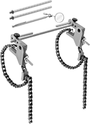
Shaft Alignment Chain Clamps
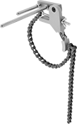 |
Install a test indicator on each holding rod to check for shaft misalignment.
Body | Mounting | |||||||||||
|---|---|---|---|---|---|---|---|---|---|---|---|---|
For Shaft Dia. | Chain Lg. | Lg. | Wd. | Body Material | Hole Location | Fasteners Included | No. of Holes | Hole Thread Size | Includes | Each | ||
| 1" to 6" | 24" | 3 5/8" | 3/4" | Stainless Steel | Side | Yes | 3 | 1/4"-28 | ANSI No. 41 Chain (6" Dia. Capacity) One 5/16" Dia. × 3-1/4" Lg. Stainless Steel Holding Rod One 5/16" Dia. × 6-1/2” Lg. Stainless Steel Holding Rod | 21025A21 | 0000000 | |
| 0" to 9" | 24" | 3" | 3" | Aluminum | — | — | — | — | ANSI No. 41 Chain (9” Dia. Capacity) One 5/16” Dia. × 3” Lg. Stainless Steel Holding Rod One 5/16” Dia. × 6” Lg. Stainless Steel Holding Rod | 2593A11 | 000000 | |
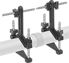
Dial-Indicator Shaft Alignment Chain Clamp Kits
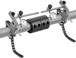 |
 |  |
Back Plunger | Bottom Plunger |
Find misalignment across adjacent shafts—these clamps position a dial indicator on each shaft to locate offset or angular misalignment in both the horizontal and vertical axes.
Continuous—Continuous dials are numbered clockwise around the face for direct measurement.
Balanced—Balanced dials are more versatile than continuous dials because they help detect misalignment in both directions. They have a center zero with positive values on one side and negative values on the other.
Back Plunger—Back plungers take up less space in your set up because their plunger sits flush against the shaft. They mount in multiple orientations to fit in a variety of set ups.
Bottom Plunger—Bottom plungers are oriented best to detect vertical misalignment. They’re also mountable and allow you to see the shaft and dial indicator at the same time, giving you accurate readings.
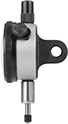
Dial Indicator | |||||||||
|---|---|---|---|---|---|---|---|---|---|
For Shaft Dia. | Dial Type | Plunger Location | Measuring Increments | Measurement Range | Container Type | Includes | Each | ||
| 0" to 9" | Continuous | Back | 0.001" | 0" to 0.2" | Case | Inspection Mirror Two Dial Indicators Two Swivel Clamps | 2593A13 | 000000000 | |
| 0" to 9" | Balanced | Back | 0.001" | 0" to 0.2" | Case | Inspection Mirror Two Dial Indicators Two Swivel Clamps | 2593A14 | 00000000 | |
| 0" to 9" | Balanced | Bottom | 0.001" | 0" to 0.3" | Case | Inspection Mirror Two Dial Indicators Two Swivel Clamps | 2593A15 | 00000000 | |
Shaft Alignment Chain Clamp Kits
 |
For Shaft Dia. | Container Type | Includes | Each | ||
|---|---|---|---|---|---|
| 0" to 9" | Case | Inspection Mirror Two Chain Clamps | 2593A12 | 0000000 |
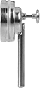
Stylus-Indicator Shaft Alignment Clamp Kits
 |
Use stylus movement to check for misalignment. Kits include two sets of mounting brackets with adjustment knobs.
Proximity-Sensor Shaft Alignment Kits
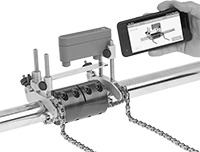 |
Align rotary shafts with the help of a mobile app. These sensor kits are more accurate than straightedges and easier to use than dial indicators. Properly aligning shafts reduces vibration and protects couplings, bearings, and other parts from wear and damage.
Use the included chain clamps to mount these sensors above your coupling, where they detect the degree of misalignment between the shafts. The app shows live animations to give step-by-step instructions for repositioning your equipment. Once the shafts are aligned, the app saves a report documenting the process.
Good for extended use in industrial environments, these sensors last up to 18 hours between charges and are IP54 rated for protection from dust.
Cannot Be Sold To—They cannot be sold to the listed areas due to energy efficiency regulations.
Battery | ||||||||||||||
|---|---|---|---|---|---|---|---|---|---|---|---|---|---|---|
For Shaft Dia. | Max. Horiz. Clearance | Max. Coupling Ht. | Accuracy | Operating System Compatibility | Container Type | Includes | Type | Life, hr. | Enclosure Rating | Certificate Type | Cannot Be Sold To | Each | ||
| 7/8" to 6 1/4" | 7.3" | 2.2" | ±0.5° | Android 4.4.2 or Later iOS 9.0 or Later | Plastic Case | One Measuring Unit with Two Proximity Sensors Three Reference Bars (4", 6", and 8" Lg.) Two Chain Clamps One Tape Measure One USB Charging Cable | Rechargeable | 18 | IP54 | Calibration Certificate | California, Oregon | 3631N11 | 000000000 | |
