


Filter by
Wire Connection


Width

Grounding
Height
Performance
Length
Electrical Connection
Export Control Classification Number (ECCN)
U.S.–Mexico–Canada Agreement (USMCA) Qualifying
DFARS Specialty Metals
Modular DIN-Rail Mount Terminal Blocks
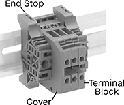 |
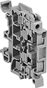
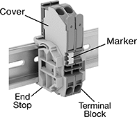
Mix and match these terminal blocks to get the exact number of circuits you need in a single setup. Add blocks for thermocouples, fuses, and grounding wire as needed. The blocks clip side by side onto DIN rail in control panels, creating tidy rows of circuits that you can identify and access on the spot.
The screw-clamp terminals flatten your wire so it stays put when vibrated or pulled. If you need to change wiring frequently without adjusting a screw, consider a quick-connect terminal block with spring-clamp or lever-clamp terminals.
Ground Terminal Blocks with Screw-Clamp Terminals
 |
Connect grounding wire to DIN rail so fault currents can safely flow to ground. These terminal blocks should only be used for grounding circuits.
End Stops—Mount at the end of a group of terminal blocks so they don't slide when vibrated or bumped.
Terminal Blocks | End Stops | |||||||||||||
|---|---|---|---|---|---|---|---|---|---|---|---|---|---|---|
Each | ||||||||||||||
No. of Circuits | No. of Terminals per Circuit | For Wire Ga. | Wd., mm | Ht., mm | Color | For DIN Rail Trade Size | Enclosure Rating | 1-24 | 25-Up | Each | ||||
| 1 | 2 | 22 to 12 | 5 | 43.5 | Green/Yellow | 1, 3 | IP20 | 7641K931 | 00000 | 00000 | 7641K35 | 00000 | ||
| 1 | 2 | 22 to 12 | 6 | 43.8 | Green/Yellow | 1, 3 | IP20 | 7641K81 | 0000 | 0000 | 7641K35 | 0000 | ||
| 1 | 2 | 22 to 8 | 8 | 43.8 | Green/Yellow | 1, 3 | IP20 | 7641K82 | 0000 | 0000 | 7641K35 | 0000 | ||
| 1 | 2 | 20 to 6 | 10 | 43.8 | Green/Yellow | 1, 3 | IP20 | 7641K83 | 0000 | 0000 | 7641K35 | 0000 | ||
| 1 | 2 | 14 to 4 | 12 | 49.5 | Green/Yellow | 1, 3 | IP20 | 7641K171 | 0000 | 0000 | 7641K35 | 0000 | ||
| 1 | 2 | 8 to 1/0 | 16 | 49 | Green/Yellow | 1, 3 | IP20 | 7641K181 | 00000 | 0000 | 7641K35 | 0000 | ||
| 1 | 4 | 22 to 10 | 6 | 63.5 | Green/Yellow | 1, 3 | IP20 | 7641K847 | 0000 | 0000 | 7641K35 | 0000 | ||
| 1 | 7 | 22 to 12 | 6 | 90 | Green/Yellow | 1, 3 | IP20 | 7641K848 | 00000 | 00000 | 7641K757 | 0000 | ||
Each | |||||||||||||||||||||||||||||||||||||||||||||||||||||||||||||||||||||||||||||||||||||||||||||||||||
|---|---|---|---|---|---|---|---|---|---|---|---|---|---|---|---|---|---|---|---|---|---|---|---|---|---|---|---|---|---|---|---|---|---|---|---|---|---|---|---|---|---|---|---|---|---|---|---|---|---|---|---|---|---|---|---|---|---|---|---|---|---|---|---|---|---|---|---|---|---|---|---|---|---|---|---|---|---|---|---|---|---|---|---|---|---|---|---|---|---|---|---|---|---|---|---|---|---|---|---|
For No. of Circuits | For Terminal Block Wd., mm | Number Range | Markers per Card | Color | 1-24 | 25-Up | |||||||||||||||||||||||||||||||||||||||||||||||||||||||||||||||||||||||||||||||||||||||||||||
Blank | |||||||||||||||||||||||||||||||||||||||||||||||||||||||||||||||||||||||||||||||||||||||||||||||||||
| 1, 2 | 5 | — | 100 | White | 7641K983 | 00000 | 00000 | ||||||||||||||||||||||||||||||||||||||||||||||||||||||||||||||||||||||||||||||||||||||||||||
| 1, 2 | 6 | — | 100 | White | 7641K19 | 0000 | 0000 | ||||||||||||||||||||||||||||||||||||||||||||||||||||||||||||||||||||||||||||||||||||||||||||
| 1, 2 | 8, 10, 12, 13, 16, 22 | — | 100 | White | 7641K981 | 0000 | 0000 | ||||||||||||||||||||||||||||||||||||||||||||||||||||||||||||||||||||||||||||||||||||||||||||
Numbered for Horizontal Rails | |||||||||||||||||||||||||||||||||||||||||||||||||||||||||||||||||||||||||||||||||||||||||||||||||||
| 1, 2 | 5 | 1 to 100 | 100 | White | 7641K95 | 0000 | 0000 | ||||||||||||||||||||||||||||||||||||||||||||||||||||||||||||||||||||||||||||||||||||||||||||
| 1, 2 | 5 | 101 to 200 | 100 | White | 7641K96 | 0000 | 0000 | ||||||||||||||||||||||||||||||||||||||||||||||||||||||||||||||||||||||||||||||||||||||||||||
| 1, 2 | 6 | 1 to 100 | 100 | White | 7641K75 | 0000 | 0000 | ||||||||||||||||||||||||||||||||||||||||||||||||||||||||||||||||||||||||||||||||||||||||||||
| 1, 2 | 6 | 101 to 200 | 100 | White | 7641K76 | 0000 | 0000 | ||||||||||||||||||||||||||||||||||||||||||||||||||||||||||||||||||||||||||||||||||||||||||||
| 1, 2 | 8, 10, 12, 13, 16, 22 | 1 to 100 | 100 | White | 7641K991 | 0000 | 0000 | ||||||||||||||||||||||||||||||||||||||||||||||||||||||||||||||||||||||||||||||||||||||||||||
| 1, 2 | 8, 10, 12, 13, 16, 22 | 101 to 200 | 100 | White | 7641K992 | 0000 | 0000 | ||||||||||||||||||||||||||||||||||||||||||||||||||||||||||||||||||||||||||||||||||||||||||||
Numbered for Vertical Rails | |||||||||||||||||||||||||||||||||||||||||||||||||||||||||||||||||||||||||||||||||||||||||||||||||||
| 1, 2 | 5 | 1 to 100 | 100 | White | 7641K97 | 0000 | 0000 | ||||||||||||||||||||||||||||||||||||||||||||||||||||||||||||||||||||||||||||||||||||||||||||
| 1, 2 | 5 | 101 to 200 | 100 | White | 7641K98 | 0000 | 0000 | ||||||||||||||||||||||||||||||||||||||||||||||||||||||||||||||||||||||||||||||||||||||||||||
| 1, 2 | 6 | 1 to 100 | 100 | White | 7641K77 | 0000 | 0000 | ||||||||||||||||||||||||||||||||||||||||||||||||||||||||||||||||||||||||||||||||||||||||||||
| 1, 2 | 6 | 101 to 200 | 100 | White | 7641K78 | 0000 | 0000 | ||||||||||||||||||||||||||||||||||||||||||||||||||||||||||||||||||||||||||||||||||||||||||||
| 1, 2 | 8, 10, 12, 13, 16, 22 | 1 to 100 | 100 | White | 7641K993 | 0000 | 0000 | ||||||||||||||||||||||||||||||||||||||||||||||||||||||||||||||||||||||||||||||||||||||||||||
| 1, 2 | 8, 10, 12, 13, 16, 22 | 101 to 200 | 100 | White | 7641K994 | 0000 | 0000 | ||||||||||||||||||||||||||||||||||||||||||||||||||||||||||||||||||||||||||||||||||||||||||||
Fuse Terminal Blocks with Screw-Clamp Terminals
 |
Install a fuse in the built-in fuse holder so excess current doesn't damage your equipment. If the current exceeds the limit, the fuse will blow and cut power to connected components.
Blown Fuse Indicator—A light goes on when the fuse blows, so you can spot an overloaded circuit without cutting power or touching equipment.
Covers—Snap onto the exposed side of a terminal block to prevent accidental contact with a live wire.
End Stops—Mount at the end of a group of terminal blocks so they don't slide when vibrated or bumped.
Bar Jumpers—Metal poles create an electrical connection between blocks, so you can connect multiple components with a single wire. Blocks must be the same width for the jumpers to fit. Cut jumpers to size with a hacksaw or high-force wire cutter. Add covers so jumpers don't touch the screws on the outermost blocks.
Insulation—Terminal blocks with insulated jumpers maintain their IP20 rating to prevent shocks and short circuits. Blocks with noninsulated jumpers lose their IP20 rating for touch protection because the jumpers introduce exposed metal to the circuit.
Terminal Blocks | Covers | End Stops | Bar Jumpers | ||||||||||||||||||||||||||||||||||||||||||||||||||||||||||||||||||||||||||||||||||||||||||||||||
|---|---|---|---|---|---|---|---|---|---|---|---|---|---|---|---|---|---|---|---|---|---|---|---|---|---|---|---|---|---|---|---|---|---|---|---|---|---|---|---|---|---|---|---|---|---|---|---|---|---|---|---|---|---|---|---|---|---|---|---|---|---|---|---|---|---|---|---|---|---|---|---|---|---|---|---|---|---|---|---|---|---|---|---|---|---|---|---|---|---|---|---|---|---|---|---|---|---|---|---|
For Fuse | Each | ||||||||||||||||||||||||||||||||||||||||||||||||||||||||||||||||||||||||||||||||||||||||||||||||||
No. of Circuits | No. of Terminals per Circuit | For Wire Ga. | Wd., mm | Ht., mm | Overall Dia., mm | Overall Lg., mm | Type | Circuit Status Indicator Type | Blown Fuse Indicator Voltage | For DIN Rail Trade Size | Enclosure Rating | Color | 1-24 | 25-Up | Each | Each | Insulation | Each | |||||||||||||||||||||||||||||||||||||||||||||||||||||||||||||||||||||||||||||||||
300V AC/300V DC—6.3 amp per Circuit | |||||||||||||||||||||||||||||||||||||||||||||||||||||||||||||||||||||||||||||||||||||||||||||||||||
| 2 1 (Ground) | 2 1 (Ground) | 20 to 12 | 8 | 99 | 5 | 20 | Ceramic, Glass | — | — | 3 | IP20 | Gray | 7641K861 | 000000 | 000000 | 7641K765 | 00000 | 7641K757 | 00000 | Noninsulated | 7641K16 | 000000 | |||||||||||||||||||||||||||||||||||||||||||||||||||||||||||||||||||||||||||||
| 2 1 (Ground) | 2 1 (Ground) | 20 to 12 | 8 | 99 | 5 | 20 | Ceramic, Glass | Blown Fuse | 24V DC 60V DC 110V AC | 3 | IP20 | Gray | 7641K864 | 00000 | 00000 | 7641K765 | 0000 | 7641K757 | 0000 | Noninsulated | 7641K16 | 00000 | |||||||||||||||||||||||||||||||||||||||||||||||||||||||||||||||||||||||||||||
| 2 1 (Ground) | 2 1 (Ground) | 20 to 12 | 8 | 99 | 5 | 20 | Ceramic, Glass | Blown Fuse | 110V AC 230V AC | 3 | IP20 | Gray | 7641K865 | 00000 | 00000 | 7641K765 | 0000 | 7641K757 | 0000 | Noninsulated | 7641K16 | 00000 | |||||||||||||||||||||||||||||||||||||||||||||||||||||||||||||||||||||||||||||
Blank | Numbered for Horizontal Rails | Numbered for Vertical Rails |
Each | |||||||||||||||||||||||||||||||||||||||||||||||||||||||||||||||||||||||||||||||||||||||||||||||||||
|---|---|---|---|---|---|---|---|---|---|---|---|---|---|---|---|---|---|---|---|---|---|---|---|---|---|---|---|---|---|---|---|---|---|---|---|---|---|---|---|---|---|---|---|---|---|---|---|---|---|---|---|---|---|---|---|---|---|---|---|---|---|---|---|---|---|---|---|---|---|---|---|---|---|---|---|---|---|---|---|---|---|---|---|---|---|---|---|---|---|---|---|---|---|---|---|---|---|---|---|
For No. of Circuits | For Terminal Block Wd., mm | Number Range | Markers per Card | Color | 1-24 | 25-Up | |||||||||||||||||||||||||||||||||||||||||||||||||||||||||||||||||||||||||||||||||||||||||||||
Blank | |||||||||||||||||||||||||||||||||||||||||||||||||||||||||||||||||||||||||||||||||||||||||||||||||||
| 1, 2 | 8, 10, 12, 13, 16, 22 | — | 100 | White | 7641K981 | 00000 | 00000 | ||||||||||||||||||||||||||||||||||||||||||||||||||||||||||||||||||||||||||||||||||||||||||||
Numbered for Horizontal Rails | |||||||||||||||||||||||||||||||||||||||||||||||||||||||||||||||||||||||||||||||||||||||||||||||||||
| 1, 2 | 8, 10, 12, 13, 16, 22 | 1 to 100 | 100 | White | 7641K991 | 0000 | 0000 | ||||||||||||||||||||||||||||||||||||||||||||||||||||||||||||||||||||||||||||||||||||||||||||
| 1, 2 | 8, 10, 12, 13, 16, 22 | 101 to 200 | 100 | White | 7641K992 | 0000 | 0000 | ||||||||||||||||||||||||||||||||||||||||||||||||||||||||||||||||||||||||||||||||||||||||||||
Numbered for Vertical Rails | |||||||||||||||||||||||||||||||||||||||||||||||||||||||||||||||||||||||||||||||||||||||||||||||||||
| 1, 2 | 8, 10, 12, 13, 16, 22 | 1 to 100 | 100 | White | 7641K993 | 0000 | 0000 | ||||||||||||||||||||||||||||||||||||||||||||||||||||||||||||||||||||||||||||||||||||||||||||
| 1, 2 | 8, 10, 12, 13, 16, 22 | 101 to 200 | 100 | White | 7641K994 | 0000 | 0000 | ||||||||||||||||||||||||||||||||||||||||||||||||||||||||||||||||||||||||||||||||||||||||||||
Quick-Connect Modular DIN-Rail Mount Terminal Blocks
 |
Pop wire in and out of these terminal blocks without adjusting a screw. Lift the clamp with a screwdriver or built-in lever, then release the clamp down onto the wire. Once clamped in place, the wire will stay put when vibrated, bent, or pulled.
Mix and match these terminal blocks to get the exact number of circuits you need in a single setup. Add blocks for thermocouples, fuses, and grounding wire as needed. The blocks clip side by side onto DIN rail in control panels, creating tidy rows of circuits that you can identify and access on the spot.
Ground Terminal Blocks with Spring-Clamp Terminals
Connect grounding wire to DIN rail so fault currents can safely flow to ground. These terminal blocks should only be used for grounding circuits.
Covers—Snap onto the exposed side of a terminal block to prevent accidental contact with a live wire.
End Stops—Mount at the end of a group of terminal blocks so they don't slide when vibrated or bumped.
Adjacent Jumpers—Metal poles create an electrical connection between adjacent terminal blocks, so you can connect multiple components with a single wire. Blocks must be the same width for the jumpers to fit.
Terminal Blocks | Covers | End Stops | Adjacent Jumpers | |||||||||||||||
|---|---|---|---|---|---|---|---|---|---|---|---|---|---|---|---|---|---|---|
Each | ||||||||||||||||||
No. of Circuits | No. of Terminals per Circuit | For Wire Ga. | Wd., mm | Ht., mm | Color | For DIN Rail Trade Size | 1-24 | 25-Up | Each | Each | Insulation | Each | ||||||
| 1 | 2 | 28 to 12 | 5 | 53 | Green/Yellow | 3 | 9473T82 | 000000 | 000000 | 9473T131 | 00000 | 9473T144 | 00000 | Insulated | 9473T114 | 00000 | ||
| 1 | 2 | 28 to 12 | 6 | 59 | Green/Yellow | 3 | 9473T86 | 00000 | 00000 | 9473T134 | 0000 | 9473T144 | 0000 | Insulated | 9473T117 | 0000 | ||
| 1 | 2 | 24 to 10 | 8 | 74.5 | Green/Yellow | 3 | 9473T91 | 00000 | 00000 | 9473T137 | 0000 | 9473T144 | 0000 | Insulated | 9473T121 | 0000 | ||
| 1 | 2 | 24 to 8 | 10 | 78 | Green/Yellow | 3 | 9473T94 | 00000 | 00000 | 9473T139 | 0000 | 9473T144 | 0000 | Insulated | 9473T124 | 0000 | ||
| 1 | 2 | 24 to 6 | 12 | 94.5 | Green/Yellow | 3 | 9473T97 | 00000 | 00000 | 9473T142 | 0000 | 9473T144 | 0000 | Insulated | 9473T127 | 0000 | ||
| 1 | 2 | 22 to 14 | 4.2 | 50.8 | Green/Yellow | 3 | 9473T187 | 0000 | 0000 | 9473T191 | 0000 | 9473T144 | 0000 | — | ——— | 0 | ||
| 1 | 2 | 8 to 2 | 16 | 100 | Green/Yellow | 3 | 9473T99 | 00000 | 00000 | ——— | 0 | 9473T144 | 0000 | — | ——— | 0 | ||
| 1 | 2 | 4 to 4/0 | 25 | 107 | Green/Yellow | 3 | 9473T111 | 00000 | 00000 | ——— | 0 | 9473T144 | 0000 | — | ——— | 0 | ||
| 1 | 3 | 28 to 12 | 5 | 64 | Green/Yellow | 3 | 9473T83 | 00000 | 00000 | 9473T132 | 0000 | 9473T144 | 0000 | Insulated | 9473T114 | 0000 | ||
| 1 | 3 | 28 to 12 | 6 | 73.5 | Green/Yellow | 3 | 9473T87 | 00000 | 00000 | 9473T135 | 0000 | 9473T144 | 0000 | Insulated | 9473T117 | 0000 | ||
| 1 | 3 | 24 to 10 | 8 | 93 | Green/Yellow | 3 | 9473T92 | 00000 | 00000 | 9473T138 | 0000 | 9473T144 | 0000 | Insulated | 9473T121 | 0000 | ||
| 1 | 3 | 24 to 8 | 10 | 97.5 | Green/Yellow | 3 | 9473T95 | 00000 | 00000 | 9473T141 | 0000 | 9473T144 | 0000 | Insulated | 9473T124 | 0000 | ||
| 1 | 3 | 24 to 6 | 12 | 104.5 | Green/Yellow | 3 | 9473T98 | 00000 | 00000 | 9473T143 | 0000 | 9473T144 | 0000 | Insulated | 9473T127 | 0000 | ||
| 1 | 3 | 22 to 14 | 4.2 | 59.5 | Green/Yellow | 3 | 9473T188 | 0000 | 0000 | 9473T192 | 0000 | 9473T144 | 0000 | — | ——— | 0 | ||
| 1 | 4 | 28 to 12 | 5 | 64 | Green/Yellow | 3 | 9473T155 | 00000 | 00000 | 9473T154 | 0000 | 9473T144 | 0000 | Insulated | 9473T114 | 0000 | ||
| 1 | 4 | 28 to 12 | 5 | 75 | Green/Yellow | 3 | 9473T84 | 00000 | 00000 | 9473T133 | 0000 | 9473T144 | 0000 | Insulated | 9473T114 | 0000 | ||
| 1 | 4 | 28 to 12 | 6 | 86 | Green/Yellow | 3 | 9473T88 | 00000 | 00000 | 9473T136 | 0000 | 9473T144 | 0000 | Insulated | 9473T117 | 0000 | ||
| 1 | 4 | 22 to 14 | 4.2 | 70 | Green/Yellow | 3 | 9473T189 | 0000 | 0000 | 9473T195 | 0000 | 9473T144 | 0000 | — | ——— | 0 | ||
Blank | Numbered for Horizontal Rails | Numbered for Vertical Rails |
Each | |||||||||||||||||||||||||||||||||||||||||||||||||||||||||||||||||||||||||||||||||||||||||||||||||||
|---|---|---|---|---|---|---|---|---|---|---|---|---|---|---|---|---|---|---|---|---|---|---|---|---|---|---|---|---|---|---|---|---|---|---|---|---|---|---|---|---|---|---|---|---|---|---|---|---|---|---|---|---|---|---|---|---|---|---|---|---|---|---|---|---|---|---|---|---|---|---|---|---|---|---|---|---|---|---|---|---|---|---|---|---|---|---|---|---|---|---|---|---|---|---|---|---|---|---|---|
For Terminal Block Wd., mm | Number Range | Includes | Markers per Card | Color | 1-24 | 25-Up | |||||||||||||||||||||||||||||||||||||||||||||||||||||||||||||||||||||||||||||||||||||||||||||
Blank | |||||||||||||||||||||||||||||||||||||||||||||||||||||||||||||||||||||||||||||||||||||||||||||||||||
| 4.2 | — | — | 100 | White | 9473T217 | 00000 | 00000 | ||||||||||||||||||||||||||||||||||||||||||||||||||||||||||||||||||||||||||||||||||||||||||||
| 5, 6, 8, 10, 12, 16, 25 | — | — | 100 | White | 9473T145 | 0000 | 0000 | ||||||||||||||||||||||||||||||||||||||||||||||||||||||||||||||||||||||||||||||||||||||||||||
Numbered for Horizontal Rails | |||||||||||||||||||||||||||||||||||||||||||||||||||||||||||||||||||||||||||||||||||||||||||||||||||
| 4.2 | 1 to 50 | Two of Each Number | 100 | White | 9473T218 | 00000 | 0000 | ||||||||||||||||||||||||||||||||||||||||||||||||||||||||||||||||||||||||||||||||||||||||||||
| 5, 6, 8, 10, 12, 16, 25 | 1 to 50 | Two of Each Number | 100 | White | 9473T146 | 00000 | 0000 | ||||||||||||||||||||||||||||||||||||||||||||||||||||||||||||||||||||||||||||||||||||||||||||
Numbered for Vertical Rails | |||||||||||||||||||||||||||||||||||||||||||||||||||||||||||||||||||||||||||||||||||||||||||||||||||
| 4.2 | 1 to 50 | Two of Each Number | 100 | White | 9473T219 | 00000 | 00000 | ||||||||||||||||||||||||||||||||||||||||||||||||||||||||||||||||||||||||||||||||||||||||||||
| 5, 6, 8, 10, 12, 16, 25 | 1 to 50 | Two of Each Number | 100 | White | 9473T147 | 00000 | 00000 | ||||||||||||||||||||||||||||||||||||||||||||||||||||||||||||||||||||||||||||||||||||||||||||
Ground Terminal Blocks with Lever- and Spring-Clamp Terminals
Connect grounding wire to DIN rail so fault currents can safely flow to ground. These terminal blocks should only be used for grounding circuits.
Covers—Snap onto the exposed side of a terminal block to prevent accidental contact with a live wire.
End Stops—Mount at the end of a group of terminal blocks so they don't slide when vibrated or bumped.
Adjacent Jumpers—Metal poles create an electrical connection between adjacent terminal blocks, so you can connect multiple components with a single wire. Blocks must be the same width for the jumpers to fit.
Terminal Blocks | Covers | End Stops | Adjacent Jumpers | ||||||||||||||
|---|---|---|---|---|---|---|---|---|---|---|---|---|---|---|---|---|---|
No. of Circuits | No. of Terminals per Circuit | For Wire Ga. | Wd., mm | Ht., mm | Color | For DIN Rail Trade Size | Each | Each | Each | Insulation | Each | ||||||
| 1 | 1 (Lever Clamp) 1 (Spring Clamp) | 22 to 12 | 5.2 | 63.8 | Green/Yellow | 3 | 4036N13 | 00000 | 4036N201 | 00000 | 9473T144 | 00000 | Insulated | 4036N301 | 00000 | ||
| 1 | 1 (Lever Clamp) 1 (Spring Clamp) | 20 to 10 | 6.2 | 70.7 | Green/Yellow | 3 | 4036N19 | 00000 | 4036N203 | 0000 | 9473T144 | 0000 | Insulated | 4036N302 | 0000 | ||
| 1 | 1 (Lever Clamp) 1 (Spring Clamp) | 20 to 8 | 7.5 | 75.2 | Green/Yellow | 3 | 4036N26 | 00000 | 4036N205 | 0000 | 9473T144 | 0000 | Insulated | 4036N303 | 0000 | ||
| 1 | 1 (Lever Clamp) 1 (Spring Clamp) | 20 to 6 | 10 | 89 | Green/Yellow | 3 | 4036N33 | 00000 | 4036N207 | 0000 | 9473T144 | 0000 | Insulated | 4036N304 | 0000 | ||
| 1 | 1 (Lever Clamp) 1 (Spring Clamp) | 20 to 6 | 12 | 91.5 | Green/Yellow | 3 | 4036N39 | 00000 | 4036N209 | 0000 | 9473T144 | 0000 | Insulated | 4036N305 | 0000 | ||
| 1 | 1 (Lever Clamp) 2 (Spring Clamp) | 22 to 12 | 5.2 | 72.2 | Green/Yellow | 3 | 4036N16 | 00000 | 4036N202 | 0000 | 9473T144 | 0000 | Insulated | 4036N301 | 0000 | ||
| 1 | 1 (Lever Clamp) 2 (Spring Clamp) | 20 to 10 | 6.2 | 83.2 | Green/Yellow | 3 | 4036N23 | 00000 | 4036N204 | 0000 | 9473T144 | 0000 | Insulated | 4036N302 | 0000 | ||
| 1 | 1 (Lever Clamp) 2 (Spring Clamp) | 20 to 8 | 7.5 | 91.2 | Green/Yellow | 3 | 4036N29 | 00000 | 4036N206 | 0000 | 9473T144 | 0000 | Insulated | 4036N303 | 0000 | ||
| 1 | 1 (Lever Clamp) 2 (Spring Clamp) | 20 to 6 | 10 | 110.4 | Green/Yellow | 3 | 4036N36 | 00000 | 4036N208 | 0000 | 9473T144 | 0000 | Insulated | 4036N304 | 0000 | ||
| 1 | 1 (Lever Clamp) 2 (Spring Clamp) | 20 to 6 | 12 | 113.5 | Green/Yellow | 3 | 4036N43 | 00000 | 4036N211 | 0000 | 9473T144 | 0000 | Insulated | 4036N305 | 0000 | ||
Blank |
For Terminal Block Wd., mm | Markers per Card | Color | Each | ||||||||||||||||||||||||||||||||||||||||||||||||||||||||||||||||||||||||||||||||||||||||||||||||
|---|---|---|---|---|---|---|---|---|---|---|---|---|---|---|---|---|---|---|---|---|---|---|---|---|---|---|---|---|---|---|---|---|---|---|---|---|---|---|---|---|---|---|---|---|---|---|---|---|---|---|---|---|---|---|---|---|---|---|---|---|---|---|---|---|---|---|---|---|---|---|---|---|---|---|---|---|---|---|---|---|---|---|---|---|---|---|---|---|---|---|---|---|---|---|---|---|---|---|---|
Blank | |||||||||||||||||||||||||||||||||||||||||||||||||||||||||||||||||||||||||||||||||||||||||||||||||||
| 5.2, 6.2, 7.5, 10, 12 | 100 | White | 4036N401 | 00000 | |||||||||||||||||||||||||||||||||||||||||||||||||||||||||||||||||||||||||||||||||||||||||||||||
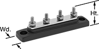
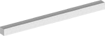
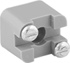
Harsh-Environment High-Current Distribution Bars
 | 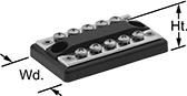 |
Stud Terminals 1 Circuit | Screw Terminals 2 Circuits |
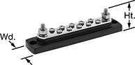 | 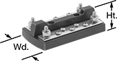 |
Stud and Screw Terminals 1 Circuit | Stud and Screw Terminals 2 Circuits |
Distribution Bars | Distribution Bar Covers | ||||||||||||||||||||||||||||||||||||||||||||||||||||||||||||||||||||||||||||||||||||||||||||||||||
|---|---|---|---|---|---|---|---|---|---|---|---|---|---|---|---|---|---|---|---|---|---|---|---|---|---|---|---|---|---|---|---|---|---|---|---|---|---|---|---|---|---|---|---|---|---|---|---|---|---|---|---|---|---|---|---|---|---|---|---|---|---|---|---|---|---|---|---|---|---|---|---|---|---|---|---|---|---|---|---|---|---|---|---|---|---|---|---|---|---|---|---|---|---|---|---|---|---|---|---|
Stud Terminals | Screw Terminals | Mounting Holes | |||||||||||||||||||||||||||||||||||||||||||||||||||||||||||||||||||||||||||||||||||||||||||||||||
Voltage | Current | No. per Circuit | Size | No. per Circuit | Size | Lg. | Wd. | Ht. | Mounting Fasteners Included | Dia. | No. of | Certification | Each | Each | |||||||||||||||||||||||||||||||||||||||||||||||||||||||||||||||||||||||||||||||||||||
Stud Terminals | |||||||||||||||||||||||||||||||||||||||||||||||||||||||||||||||||||||||||||||||||||||||||||||||||||
1 Circuit | |||||||||||||||||||||||||||||||||||||||||||||||||||||||||||||||||||||||||||||||||||||||||||||||||||
| 300V AC 48V DC | 100 amp 100 amp | 4 | No. 10 | — | — | 4 3/16" | 7/8" | 1 1/8" | No | 0.21" | 2 | CE Marked | 9290T32 | 000000 | 9290T27 | 00000 | |||||||||||||||||||||||||||||||||||||||||||||||||||||||||||||||||||||||||||||||||||
| 300V AC 48V DC | 130 amp 150 amp | 4 | 1/4" | — | — | 5 7/8" | 1 1/4" | 1 1/2" | No | 0.21" | 2 | CE Marked | 9290T16 | 00000 | 9290T21 | 0000 | |||||||||||||||||||||||||||||||||||||||||||||||||||||||||||||||||||||||||||||||||||
| 300V AC 48V DC | 250 amp 250 amp | 4 | 5/16" | — | — | 5 7/8" | 1 1/2" | 1 11/16" | No | 0.21" | 2 | CE Marked | 9290T17 | 00000 | 9290T29 | 00000 | |||||||||||||||||||||||||||||||||||||||||||||||||||||||||||||||||||||||||||||||||||
| 300V AC 48V DC | 250 amp 250 amp | 6 | 5/16" | — | — | 7 3/4" | 1 1/2" | 1 11/16" | No | 0.21" | 2 | CE Marked | 9290T8 | 000000 | 9290T28 | 00000 | |||||||||||||||||||||||||||||||||||||||||||||||||||||||||||||||||||||||||||||||||||
Screw Terminals | |||||||||||||||||||||||||||||||||||||||||||||||||||||||||||||||||||||||||||||||||||||||||||||||||||
2 Circuits | |||||||||||||||||||||||||||||||||||||||||||||||||||||||||||||||||||||||||||||||||||||||||||||||||||
| 300V AC 48V DC | 100 amp 100 amp | — | — | 5 | No. 8 | 3" | 1 13/16" | 9/16" | No | 0.21" | 2 | CE Marked | 9290T12 | 00000 | 9290T25 | 00000 | |||||||||||||||||||||||||||||||||||||||||||||||||||||||||||||||||||||||||||||||||||
| 300V AC 48V DC | 100 amp 100 amp | — | — | 10 | No. 8 | 5 1/16" | 1 13/16" | 9/16" | No | 0.21" | 2 | CE Marked | 9290T13 | 00000 | 9290T26 | 00000 | |||||||||||||||||||||||||||||||||||||||||||||||||||||||||||||||||||||||||||||||||||
Stud and Screw Terminals | |||||||||||||||||||||||||||||||||||||||||||||||||||||||||||||||||||||||||||||||||||||||||||||||||||
1 Circuit | |||||||||||||||||||||||||||||||||||||||||||||||||||||||||||||||||||||||||||||||||||||||||||||||||||
| 300V AC 48V DC | 100 amp 100 amp | 2 | No. 10 | 5 | No. 8 | 4 3/16" | 7/8" | 1 1/8" | No | 0.21" | 2 | CE Marked | 9290T31 | 00000 | 9290T27 | 0000 | |||||||||||||||||||||||||||||||||||||||||||||||||||||||||||||||||||||||||||||||||||
| 300V AC 48V DC | 130 amp 150 amp | 2 | 1/4" | 10 | No. 8 | 5 7/8" | 1 1/4" | 1 1/2" | No | 0.21" | 2 | CE Marked | 9290T14 | 00000 | 9290T21 | 0000 | |||||||||||||||||||||||||||||||||||||||||||||||||||||||||||||||||||||||||||||||||||
| 300V AC 48V DC | 130 amp 150 amp | 2 | 1/4" | 20 | No. 8 | 9 1/8" | 1 1/4" | 1 1/2" | No | 0.21" | 2 | CE Marked | 9290T15 | 00000 | 9290T24 | 00000 | |||||||||||||||||||||||||||||||||||||||||||||||||||||||||||||||||||||||||||||||||||
| 300V AC 48V DC | 250 amp 250 amp | 2 | 5/16" | 6 | No. 10 | 5 7/8" | 1 1/2" | 1 11/16" | No | 0.21" | 2 | CE Marked | 9290T9 | 00000 | 9290T29 | 00000 | |||||||||||||||||||||||||||||||||||||||||||||||||||||||||||||||||||||||||||||||||||
| 300V AC 48V DC | 250 amp 250 amp | 2 | 5/16" | 12 | No. 10 | 7 3/4" | 1 1/2" | 1 11/16" | No | 0.21" | 2 | CE Marked | 9290T18 | 00000 | 9290T28 | 00000 | |||||||||||||||||||||||||||||||||||||||||||||||||||||||||||||||||||||||||||||||||||
| 300V AC 48V DC | 545 amp 600 amp | 4 | 3/8" | 4 | No. 8 | 7" | 2" | 2" | No | 0.26" | 4 | CE Marked | 9290T3 | 000000 | 9290T23 | 00000 | |||||||||||||||||||||||||||||||||||||||||||||||||||||||||||||||||||||||||||||||||||
| 300V AC 48V DC | 545 amp 600 amp | 8 | 3/8" | 4 | No. 8 | 11 3/8" | 2" | 2" | No | 0.39" | 4 | CE Marked | 9290T7 | 000000 | ——— | 0 | |||||||||||||||||||||||||||||||||||||||||||||||||||||||||||||||||||||||||||||||||||
2 Circuits | |||||||||||||||||||||||||||||||||||||||||||||||||||||||||||||||||||||||||||||||||||||||||||||||||||
| 300V AC 48V DC | 130 amp 150 amp | 2 | 1/4" | 5 | No. 10 | 4 7/8" | 2 9/16" | 1 1/4" | No | 0.21" | 2 | CE Marked | 9290T11 | 00000 | ——— | 0 | |||||||||||||||||||||||||||||||||||||||||||||||||||||||||||||||||||||||||||||||||||
Modular Distribution Bars
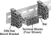 |
Build your own distribution system for neutral and grounding applications by adding terminal blocks to these bars. Slide blocks onto the bar, also known as a bus bar, and then attach mounting brackets to the bar. All wires make contact with the bar, distributing the current among the terminal blocks.
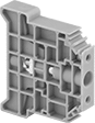
Terminal Blocks
 |
Terminal blocks have screw-clamp terminals that secure the wire as well as the block to the bar. Blocks are UL recognized for grounding applications.
Terminal Blocks | Terminal Block Markers | ||||||||||||
|---|---|---|---|---|---|---|---|---|---|---|---|---|---|
No. of Circuits | For Wire Ga. | Wire Connection | Wd., mm | Lg., mm | Ht., mm | Certification | Pkg. Qty. | Pkg. | Pkg. Qty. | Pkg. | |||
| 1 | 22, 20, 18, 16, 14, 12, 10 | Screw-Clamp Terminal | 7.5 | 30 | 23.3 | UL Recognized Component | 5 | 1529T11 | 00000 | 100 | 1529T33 | 00000 | |
| 1 | 10, 8, 6, 4 | Screw-Clamp Terminal | 9.8 | 36 | 23.3 | UL Recognized Component | 5 | 1529T12 | 0000 | 100 | 1529T34 | 0000 | |
| 1 | 8, 6, 4, 2 | Screw-Clamp Terminal | 14.5 | 45 | 27.3 | UL Recognized Component | 5 | 1529T13 | 00000 | 100 | 1529T34 | 0000 | |
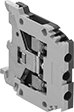
Space-Saving Modular DIN-Rail Mount Terminal Blocks
|
These handle the same voltage and power as our other modular blocks while taking up about half the vertical space. Snap them onto DIN 2 rail (also known as mini rail), which is lower in height than DIN 3 rail.
The screw-clamp or spring-clamp terminals flatten your wire so it stays put when vibrated or pulled. For an even stronger and more conductive connection, crimp a terminal or wire ferrule onto the end of the wire.
Mix and match blocks to get the exact number of circuits you need in a single setup. Add terminal blocks for fuses and grounding wire as needed. The blocks clip side by side onto DIN rail in control panels, creating tidy rows of circuits that you can identify and access on the spot.
Ground Terminal Blocks with Screw-Clamp Terminals
 |
Connect grounding wire to DIN rail so fault currents can safely flow to ground. These terminal blocks should only be used for grounding circuits.
A screw presses the clamp onto the wire for a secure hold.
Covers—Snap onto the exposed side of a terminal block to prevent accidental contact with a live wire.
End Stops—Mount at the end of a group of terminal blocks so they don't slide when vibrated or bumped.
Terminal Blocks | Covers | End Stops | ||||||||||||||
|---|---|---|---|---|---|---|---|---|---|---|---|---|---|---|---|---|
Each | ||||||||||||||||
No. of Circuits | No. of Terminals per Circuit | For Wire Ga. | Wd., mm | Ht., mm | Color | For DIN Rail Trade Size | Enclosure Rating | 1-24 | 25-Up | Each | Each | |||||
| 1 | 2 | 22 to 12 | 6 | 28 | Green/Yellow | 2 | IP20 | 7641K63 | 00000 | 00000 | 7641K961 | 00000 | 7641K69 | 00000 | ||
Blank | Numbered for Horizontal Rails | Numbered for Vertical Rails |
Each | |||||||||||||||||||||||||||||||||||||||||||||||||||||||||||||||||||||||||||||||||||||||||||||||||||
|---|---|---|---|---|---|---|---|---|---|---|---|---|---|---|---|---|---|---|---|---|---|---|---|---|---|---|---|---|---|---|---|---|---|---|---|---|---|---|---|---|---|---|---|---|---|---|---|---|---|---|---|---|---|---|---|---|---|---|---|---|---|---|---|---|---|---|---|---|---|---|---|---|---|---|---|---|---|---|---|---|---|---|---|---|---|---|---|---|---|---|---|---|---|---|---|---|---|---|---|
For No. of Circuits | For Terminal Block Wd., mm | Number Range | Markers per Card | Color | 1-24 | 25-Up | |||||||||||||||||||||||||||||||||||||||||||||||||||||||||||||||||||||||||||||||||||||||||||||
Blank | |||||||||||||||||||||||||||||||||||||||||||||||||||||||||||||||||||||||||||||||||||||||||||||||||||
| 1 | 6 | — | 100 | White | 7641K812 | 00000 | 00000 | ||||||||||||||||||||||||||||||||||||||||||||||||||||||||||||||||||||||||||||||||||||||||||||
Numbered for Horizontal Rails | |||||||||||||||||||||||||||||||||||||||||||||||||||||||||||||||||||||||||||||||||||||||||||||||||||
| 1 | 6 | 1 to 100 | 100 | White | 7641K834 | 0000 | 0000 | ||||||||||||||||||||||||||||||||||||||||||||||||||||||||||||||||||||||||||||||||||||||||||||
| 1 | 6 | 101 to 200 | 100 | White | 7641K835 | 0000 | 0000 | ||||||||||||||||||||||||||||||||||||||||||||||||||||||||||||||||||||||||||||||||||||||||||||
Numbered for Vertical Rails | |||||||||||||||||||||||||||||||||||||||||||||||||||||||||||||||||||||||||||||||||||||||||||||||||||
| 1 | 6 | 1 to 100 | 100 | White | 7641K832 | 0000 | 0000 | ||||||||||||||||||||||||||||||||||||||||||||||||||||||||||||||||||||||||||||||||||||||||||||
| 1 | 6 | 101 to 200 | 100 | White | 7641K833 | 0000 | 0000 | ||||||||||||||||||||||||||||||||||||||||||||||||||||||||||||||||||||||||||||||||||||||||||||
Quick-Connect Plug-and-Socket Modular DIN-Rail Mount Terminal Blocks
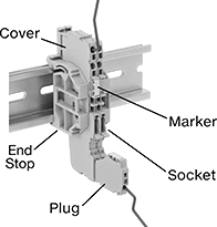 |
Cut power with the pull of a plug when you need to swap out equipment or adjust your circuit. One of the openings on these blocks is a socket, so you can wire a plug outside the enclosure and then attach it to the socket that’s already in place.
The other connections are spring clamps, so you can pop wire in and out of these terminal blocks without adjusting a screw. Lift the clamp with a screwdriver, then release the clamp down onto the wire. Once clamped in place, the wire will stay put when vibrated, bent, or pulled.
Mix and match these terminal blocks to get the exact number of circuits you need in a single setup. Add blocks for grounding wire as needed. The blocks clip side by side onto DIN rail in control panels, creating tidy rows of circuits that you can identify and access on the spot.
Ground Sockets with Spring-Clamp Terminals
Connect grounding wire to DIN rail so fault currents can safely flow to ground. These terminal blocks should only be used for grounding circuits.
Covers—Snap onto the exposed side of a terminal block to prevent accidental contact with a live wire.
End Stops—Mount at the end of a group of terminal blocks so they don't slide when vibrated or bumped.
Adjacent Jumpers—Metal poles create an electrical connection between adjacent terminal blocks, so you can connect multiple components with a single wire. Blocks must be the same width for the jumpers to fit.
Terminal Blocks | Covers | End Stops | Adjacent Jumpers | ||||||||||||||
|---|---|---|---|---|---|---|---|---|---|---|---|---|---|---|---|---|---|
No. of Circuits | No. of Terminals per Circuit | For Wire Ga. | Wd., mm | Ht., mm | Color | For DIN Rail Trade Size | Each | Each | Each | Insulation | Each | ||||||
| 1 | 1 | 24 to 16 | 3.5 | 50.8 | Green/Yellow | 3 | 4053N13 | 00000 | 4053N401 | 00000 | 9473T144 | 00000 | Insulated | 4280N401 | 00000 | ||
| 1 | 1 | 24 to 16 | 3.5 | 61.8 | Green/Yellow | 3 | 4053N16 | 0000 | 4053N402 | 0000 | 9473T144 | 0000 | Insulated | 4280N401 | 0000 | ||
| 1 | 1 | 24 to 16 | 3.5 | 85.25 | Green/Yellow | 3 | 4053N19 | 0000 | 4053N403 | 0000 | 9473T144 | 0000 | Insulated | 4280N401 | 0000 | ||
Blank |
For Terminal Block Wd., mm | Markers per Card | Color | Each | ||||||||||||||||||||||||||||||||||||||||||||||||||||||||||||||||||||||||||||||||||||||||||||||||
|---|---|---|---|---|---|---|---|---|---|---|---|---|---|---|---|---|---|---|---|---|---|---|---|---|---|---|---|---|---|---|---|---|---|---|---|---|---|---|---|---|---|---|---|---|---|---|---|---|---|---|---|---|---|---|---|---|---|---|---|---|---|---|---|---|---|---|---|---|---|---|---|---|---|---|---|---|---|---|---|---|---|---|---|---|---|---|---|---|---|---|---|---|---|---|---|---|---|---|---|
Blank | |||||||||||||||||||||||||||||||||||||||||||||||||||||||||||||||||||||||||||||||||||||||||||||||||||
| 3.5 | 100 | White | 4053N501 | 00000 | |||||||||||||||||||||||||||||||||||||||||||||||||||||||||||||||||||||||||||||||||||||||||||||||
